EP2320486A2 - Liaison entre un élément thermoélectrique et un échangeur thermique - Google Patents
Liaison entre un élément thermoélectrique et un échangeur thermique Download PDFInfo
- Publication number
- EP2320486A2 EP2320486A2 EP10014232A EP10014232A EP2320486A2 EP 2320486 A2 EP2320486 A2 EP 2320486A2 EP 10014232 A EP10014232 A EP 10014232A EP 10014232 A EP10014232 A EP 10014232A EP 2320486 A2 EP2320486 A2 EP 2320486A2
- Authority
- EP
- European Patent Office
- Prior art keywords
- heat exchanger
- thermoelectric element
- heat
- connection
- heat conducting
- Prior art date
- Legal status (The legal status is an assumption and is not a legal conclusion. Google has not performed a legal analysis and makes no representation as to the accuracy of the status listed.)
- Withdrawn
Links
Images
Classifications
-
- F—MECHANICAL ENGINEERING; LIGHTING; HEATING; WEAPONS; BLASTING
- F01—MACHINES OR ENGINES IN GENERAL; ENGINE PLANTS IN GENERAL; STEAM ENGINES
- F01N—GAS-FLOW SILENCERS OR EXHAUST APPARATUS FOR MACHINES OR ENGINES IN GENERAL; GAS-FLOW SILENCERS OR EXHAUST APPARATUS FOR INTERNAL-COMBUSTION ENGINES
- F01N3/00—Exhaust or silencing apparatus having means for purifying, rendering innocuous, or otherwise treating exhaust
- F01N3/02—Exhaust or silencing apparatus having means for purifying, rendering innocuous, or otherwise treating exhaust for cooling, or for removing solid constituents of, exhaust
- F01N3/05—Exhaust or silencing apparatus having means for purifying, rendering innocuous, or otherwise treating exhaust for cooling, or for removing solid constituents of, exhaust by means of air, e.g. by mixing exhaust with air
- F01N3/055—Exhaust or silencing apparatus having means for purifying, rendering innocuous, or otherwise treating exhaust for cooling, or for removing solid constituents of, exhaust by means of air, e.g. by mixing exhaust with air without contact between air and exhaust gases
-
- F—MECHANICAL ENGINEERING; LIGHTING; HEATING; WEAPONS; BLASTING
- F01—MACHINES OR ENGINES IN GENERAL; ENGINE PLANTS IN GENERAL; STEAM ENGINES
- F01N—GAS-FLOW SILENCERS OR EXHAUST APPARATUS FOR MACHINES OR ENGINES IN GENERAL; GAS-FLOW SILENCERS OR EXHAUST APPARATUS FOR INTERNAL-COMBUSTION ENGINES
- F01N5/00—Exhaust or silencing apparatus combined or associated with devices profiting by exhaust energy
- F01N5/02—Exhaust or silencing apparatus combined or associated with devices profiting by exhaust energy the devices using heat
- F01N5/025—Exhaust or silencing apparatus combined or associated with devices profiting by exhaust energy the devices using heat the device being thermoelectric generators
-
- H—ELECTRICITY
- H10—SEMICONDUCTOR DEVICES; ELECTRIC SOLID-STATE DEVICES NOT OTHERWISE PROVIDED FOR
- H10N—ELECTRIC SOLID-STATE DEVICES NOT OTHERWISE PROVIDED FOR
- H10N10/00—Thermoelectric devices comprising a junction of dissimilar materials, i.e. devices exhibiting Seebeck or Peltier effects
- H10N10/10—Thermoelectric devices comprising a junction of dissimilar materials, i.e. devices exhibiting Seebeck or Peltier effects operating with only the Peltier or Seebeck effects
- H10N10/13—Thermoelectric devices comprising a junction of dissimilar materials, i.e. devices exhibiting Seebeck or Peltier effects operating with only the Peltier or Seebeck effects characterised by the heat-exchanging means at the junction
-
- F—MECHANICAL ENGINEERING; LIGHTING; HEATING; WEAPONS; BLASTING
- F28—HEAT EXCHANGE IN GENERAL
- F28F—DETAILS OF HEAT-EXCHANGE AND HEAT-TRANSFER APPARATUS, OF GENERAL APPLICATION
- F28F13/00—Arrangements for modifying heat-transfer, e.g. increasing, decreasing
- F28F2013/005—Thermal joints
- F28F2013/006—Heat conductive materials
-
- Y—GENERAL TAGGING OF NEW TECHNOLOGICAL DEVELOPMENTS; GENERAL TAGGING OF CROSS-SECTIONAL TECHNOLOGIES SPANNING OVER SEVERAL SECTIONS OF THE IPC; TECHNICAL SUBJECTS COVERED BY FORMER USPC CROSS-REFERENCE ART COLLECTIONS [XRACs] AND DIGESTS
- Y02—TECHNOLOGIES OR APPLICATIONS FOR MITIGATION OR ADAPTATION AGAINST CLIMATE CHANGE
- Y02T—CLIMATE CHANGE MITIGATION TECHNOLOGIES RELATED TO TRANSPORTATION
- Y02T10/00—Road transport of goods or passengers
- Y02T10/10—Internal combustion engine [ICE] based vehicles
- Y02T10/12—Improving ICE efficiencies
Definitions
- thermoelectric element Connection between a thermoelectric element and a heat exchanger
- the present invention relates to a connection between a thermoelectric element and a heat exchanger, wherein the thermoelectric element has a ceramic carrier layer on the outside and the heat exchanger has a heat exchanger wall.
- thermoelectric generator units are arranged in an exhaust path of an internal combustion engine in order to recover energy from the exhaust gas entrained by exhaust gases.
- thermocouples are arranged in an exhaust gas passage. Due to the exhaust gas flow and the connection of the exhaust pipe to the environment creates a temperature difference. Thermoelectric elements convert using the Seebeck effect converts the temperature difference directly into electrical energy.
- thermoelectric element So that a temperature difference can occur at the thermoelectric element, this has a hot and a cold side.
- a corresponding thickness of the individual elements In order to maintain a corresponding temperature gradient in the operation of the thermoelectric element, a corresponding thickness of the individual elements is necessary. In the construction, therefore, usually a thin-film technology or a film technology is used, but can not work optimally in an exhaust system in which high temperature differences prevail.
- thermoelectric element In order to avoid an electrical short circuit and to achieve a corresponding mechanical stability, the top and bottom of the thermoelectric element is fixed by means of ceramic plates.
- the ceramic plates then form a hot side on the side facing the exhaust gas line and a cold side on the side facing away from the exhaust gas line.
- thermoelectric elements In the production of a module with thermoelectric elements, the individual modules are pressed and clamped directly with the hot or cold side in the or surrounding components.
- thermoelectric modules In the field of energy recovery from an exhaust system in the motor vehicle several thermoelectric modules are interconnected. These are placed evenly on a plane of a single component. In order to be able to realize corresponding heat transfers and uniform compressions, the surfaces of the individual components have a surface quality in the range of approximately 20 ⁇ m. This creates a high production cost, which is associated with a high cost.
- thermoelectric generator module On the side of the thermoelectric generator module, it is additionally disadvantageous that the ceramic support layer of the hot or cold side with respect on the material components used can not have a required surface quality for the most part.
- the individual assemblies are pressed together under high pressure and then braced. In this case, impermissible residual stresses occur in the individual components, in particular in the thermoelectric elements, which decisively reduce the service life of the components.
- the object of the present invention is therefore to provide thermoelectric components with a heat exchanger which realize a consistently high manufacturing quality as well as a simple production process and a high heat transfer to improve the overall efficiency.
- thermoelectric elements no longer have to be pressed with high forces, as a result of which unacceptable residual stresses are avoided.
- the cohesive connection ensures a consistently high heat transfer between the ceramic carrier layer and the heat exchanger wall by the heat conducting means.
- thermoelectric elements Another advantage of the heat-conducting is that vehicle-side vibrations that are transmitted to the system by the operation of the internal combustion engine or the driving on the road, transmitted in accordance with attenuated become. This also increases the fatigue strength of a system with thermoelectric elements.
- the heat conduction is formed as a homogeneous heat conduction layer.
- a homogeneous heat conduction layer is to be understood as a molecular structure of the materials used which remains constant in all regions of the heat conduction layer.
- a high heat transfer coefficient is achieved at the border crossings of the ceramic carrier layer to the heat conduction layer and the heat conduction layer to the heat exchanger wall.
- the heat-conducting medium has a thermal conductivity of more than 10 W / mK.
- the high thermal conductivity allows good heat dissipation, so that there is always a temperature difference in the thermoelectric components during the entire operating period. The temperature difference in turn causes a voltage generation due to the Seebeck effect.
- the heat conducting medium is formed as an alloy comprising constituents of gallium (Ga) and indium (In).
- Gallium and indium can be combined with both stainless steel and ceramics and also in itself.
- a thermal conduction agent comprising the aforementioned alloying ingredients enters into the boundary zones of the ceramic carrier layer and the heat exchanger wall.
- the compounds are in the form of bridge formations via oxygen atoms, mechanical retention and cold diffusion. They are used both for adhesion in the border zones and for heat conduction.
- Indium ensures a low surface tension and thus a good wetting ability for other metals, glass or ceramic materials. It distorts the lattices of the alloy and thereby improves the mechanical properties. Indium forms a yellow adhesive oxide, which contributes to the adhesion of ceramic materials to metals. Here, the oxidation behavior contributes significantly to the metal-ceramic composite.
- Gallium lowers the melting temperature of the alloy and thus additionally improves the flowability and mold filling capacity of the alloy.
- the alloy additionally tin (Sn) as an alloying ingredient.
- Tin reduces carbon uptake and ensures that the steel alloys to be joined are not decarburized.
- tin promotes the adhesion oxide formation of the components gallium and indium. As a result, a higher strength is brought about with the aforementioned alloying ingredients.
- the alloy preferably has a proportion of 60-80% gallium, 10-30% indium and 1-20% tin, as well as other constituents of other substances, for example bismuth or antimony.
- the alloying constituents are important for setting a specific melting temperature.
- the thermal conductivity material properties produced by the alloying ingredients must also be selected from the aspect of processing temperature and operating temperature range. Galinstan or sodium are preferably used as heat transfer agents.
- the heat exchanger wall is formed from a metallic carrier substrate.
- the carrier substrate consists of an austenitic stainless steel alloy.
- the exhaust of a vehicle has corrosive properties and a broad spectrum in both composition and operating temperatures.
- a metallic material, in particular a stainless steel alloy therefore offers a particularly good protective effect against influences by the exhaust gas combined with a consistently good and high Thermal conductivity.
- a sufficient heat transfer from the exhaust gas flow into the thermoelectric element can be promoted during the entire spectrum of possible operating points.
- the heat conducting means is formed as solder.
- soldering a correspondingly full-surface metallized ceramic carrier layer is advantageous.
- solder joints are conceivable.
- a brazing alloy or a soft solder can be used with respect to the respective operating temperature or else an active solder which can be used at a high operating temperature. In this case, no metallization of the ceramic carrier layer for entering into a cohesive connection with the solder would be necessary.
- the thermoelectric element is designed as a thermoelectric generator.
- the generator consists of a plurality of thermoelectric elements which are electrically connected to each other in series or in parallel. In order to produce a corresponding temperature gradient and to be able to keep in operation, a corresponding thickness of the individual elements is necessary.
- the thus constructed thermoelectric generator has on its top and bottom ceramic support plates, which then form a hot and a cold side. Between the hot and cold side, the temperature difference arises, which in turn generates an electrical voltage through the Seebeck effect.
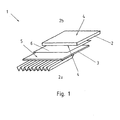
- FIG. 1 shows a compound 1 of a thermoelectric element 2 with a heat exchanger 3.
- the thermoelectric element 2 has on the outside ceramic carrier layers 4. With reference to the image plane, the underside of the thermoelectric element 2 forms a hot side 2a, the upper side of the thermoelectric element 2 forms a cold side 2b.
- the heat exchanger 3 is formed with a heat exchanger 5 wall.
- the heat exchanger wall 5 adjoins the hot side 2a of the thermoelectric element 2.
- a heat conducting means 6 is arranged between the heat exchanger wall 5 and the ceramic carrier layer 4 of the hot side 2a.
- the heat conducting means 6 connects the ceramic carrier layer 4 and the heat exchanger wall 5 cohesively. It forms a homogeneous heat conduction layer. Via the heat conduction layer, a heat flow can pass from the heat exchanger 3 into the thermoelectric element 2.
- the heat conducting means 6 preferably has the alloying elements gallium (Ga), indium (In) and tin (Sn).
- the alloy thus prepared enters into contact with the heat exchanger wall 5 and with the ceramic carrier layer 4.
- the heat exchanger wall 5 may be formed as a metallic carrier substrate or as austenitic stainless steel alloy.
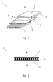
- FIG. 2 shows a sectional view through a thermoelectric generator 7.
- thermoelectric elements 2 are connected in parallel or connected in series.
- the elements connected in this way are bounded by two ceramic carrier layers 4. Between the ceramic carrier layers 4 creates a temperature difference.
- thermoelectric generator 7 On one side of the thermoelectric generator 7, a hot side 2a is produced by the application during operation, and a cold side 2b is formed on the side opposite the hot side 2a.
Landscapes
- Engineering & Computer Science (AREA)
- Chemical & Material Sciences (AREA)
- Combustion & Propulsion (AREA)
- Mechanical Engineering (AREA)
- General Engineering & Computer Science (AREA)
- Health & Medical Sciences (AREA)
- Chemical Kinetics & Catalysis (AREA)
- Toxicology (AREA)
- Heat-Exchange Devices With Radiators And Conduit Assemblies (AREA)
- Air-Conditioning For Vehicles (AREA)
- Ceramic Products (AREA)
Applications Claiming Priority (1)
| Application Number | Priority Date | Filing Date | Title |
|---|---|---|---|
| DE102009051950A DE102009051950A1 (de) | 2009-11-04 | 2009-11-04 | Verbindung zwischen einem thermoelektrischen Element und einem Wärmetauscher |
Publications (2)
| Publication Number | Publication Date |
|---|---|
| EP2320486A2 true EP2320486A2 (fr) | 2011-05-11 |
| EP2320486A3 EP2320486A3 (fr) | 2014-07-16 |
Family
ID=43530388
Family Applications (1)
| Application Number | Title | Priority Date | Filing Date |
|---|---|---|---|
| EP10014232.2A Withdrawn EP2320486A3 (fr) | 2009-11-04 | 2010-11-03 | Liaison entre un élément thermoélectrique et un échangeur thermique |
Country Status (2)
| Country | Link |
|---|---|
| EP (1) | EP2320486A3 (fr) |
| DE (1) | DE102009051950A1 (fr) |
Cited By (3)
| Publication number | Priority date | Publication date | Assignee | Title |
|---|---|---|---|---|
| DE102010054640A1 (de) * | 2010-12-15 | 2012-06-21 | Benteler Automobiltechnik Gmbh | Wärmetauscher |
| DE102011111954A1 (de) * | 2011-08-30 | 2013-02-28 | Faurecia Emissions Control Technologies, Germany Gmbh | Vorrichtung zur Abgaswärmenutzung, Abgasmodul mit einer solchen Vorrichtung sowie Verfahren zur Herstellung der Vorrichtung |
| CN111878193A (zh) * | 2020-08-26 | 2020-11-03 | 杜慎之 | 发动机排气系统散热装置 |
Family Cites Families (7)
| Publication number | Priority date | Publication date | Assignee | Title |
|---|---|---|---|---|
| DE19526822C2 (de) * | 1995-07-15 | 1998-07-02 | Euromat Gmbh | Lotlegierung, Verwendung der Lotlegierung und Verfahren zum Verbinden von Werkstücken durch Löten |
| WO1999004439A1 (fr) * | 1997-07-15 | 1999-01-28 | Sbalzarini Ivo F | Element transformateur thermoelectrique a rendement eleve et utilisation dudit element |
| US7800194B2 (en) * | 2002-04-23 | 2010-09-21 | Freedman Philip D | Thin film photodetector, method and system |
| US7032389B2 (en) * | 2003-12-12 | 2006-04-25 | Thermoelectric Design, Llc | Thermoelectric heat pump with direct cold sink support |
| JP2009087955A (ja) * | 2005-01-12 | 2009-04-23 | Showa Denko Kk | 熱電変換システムを有する廃熱回収システム |
| DE102005057763A1 (de) * | 2005-12-02 | 2007-06-06 | BSH Bosch und Siemens Hausgeräte GmbH | Thermoelektrisches Modul |
| DE102007060312B4 (de) * | 2007-08-24 | 2012-12-06 | W.E.T. Automotive Systems Ag | Elektrothermischer Wandler und Temperiereinrichtung |
-
2009
- 2009-11-04 DE DE102009051950A patent/DE102009051950A1/de not_active Withdrawn
-
2010
- 2010-11-03 EP EP10014232.2A patent/EP2320486A3/fr not_active Withdrawn
Non-Patent Citations (1)
| Title |
|---|
| None |
Cited By (5)
| Publication number | Priority date | Publication date | Assignee | Title |
|---|---|---|---|---|
| DE102010054640A1 (de) * | 2010-12-15 | 2012-06-21 | Benteler Automobiltechnik Gmbh | Wärmetauscher |
| DE102011111954A1 (de) * | 2011-08-30 | 2013-02-28 | Faurecia Emissions Control Technologies, Germany Gmbh | Vorrichtung zur Abgaswärmenutzung, Abgasmodul mit einer solchen Vorrichtung sowie Verfahren zur Herstellung der Vorrichtung |
| DE102011111954B4 (de) * | 2011-08-30 | 2016-02-18 | Faurecia Emissions Control Technologies, Germany Gmbh | Vorrichtung zur Abgaswärmenutzung, Abgasmodul mit einer solchen Vorrichtung sowie Verfahren zur Herstellung der Vorrichtung |
| US9991435B2 (en) | 2011-08-30 | 2018-06-05 | Faurecia Emissions Control Technologies, Germany Gmbh | Device for exhaust gas heat utilization, exhaust gas module having such a device, and method of manufacturing the device |
| CN111878193A (zh) * | 2020-08-26 | 2020-11-03 | 杜慎之 | 发动机排气系统散热装置 |
Also Published As
| Publication number | Publication date |
|---|---|
| DE102009051950A1 (de) | 2011-05-12 |
| EP2320486A3 (fr) | 2014-07-16 |
Similar Documents
| Publication | Publication Date | Title |
|---|---|---|
| EP2530707B1 (fr) | Procédé de préparation d'un module et le module | |
| EP0839081B1 (fr) | Alliage, notamment alliage de brasage, procede permettant d'assembler des pieces par brasage a l'aide d'un alliage de brasage et utilisation d'un alliage pour effectuer des operations de brasage | |
| DE112014002135T5 (de) | Halbleitervorrichtung und Verfahren zum Herstellen einer Halbleitervorrichtung | |
| EP2735034B1 (fr) | Module thermoélectrique et procédé de fabrication d'un module thermoélectrique | |
| DE102007046349A1 (de) | Anordnung zum Kühlen eines Leistungshalbleitermoduls | |
| DE102013206480A1 (de) | Halbleiterbauelement und Verfahren zum Herstellen eines Halbleiterbauelements | |
| DE112017000184T5 (de) | Lotverbindung | |
| DE102011083927A1 (de) | Leistungsmodul und Verfahren zur Herstellung desselben | |
| DE102013208350A1 (de) | Herstellungsverfahren für einen kühler | |
| DE102014206883A1 (de) | Thermoelektrisches Modul und Verfahren zum Herstellen desselben | |
| DE102011083926A1 (de) | Schichtverbund aus einer Trägerfolie und einer Schichtanordnung umfassend eine sinterbare Schicht aus mindestens einem Metallpulver und eine Lotschicht | |
| EP1989741A2 (fr) | Procede pour produire des modules a effet peltier, et module peltier ainsi obtenu | |
| DE102019106988A1 (de) | Batterielasche mit einer lokalisierten schweissverbindung und verfahren zu deren herstellung | |
| EP2466086A1 (fr) | Echangeur thermique | |
| DE60211235T2 (de) | Substratplatte für Halbleiter und für Leistungsmodule | |
| EP2320486A2 (fr) | Liaison entre un élément thermoélectrique et un échangeur thermique | |
| DE102010001666A1 (de) | Elektrisches oder elektronisches Verbundbauteil | |
| DE102018119772A1 (de) | Transiente Flüssigphasen-Bindungszusammensetzungen und Leistungselektronikbauteile, welche dieselben beinhalten | |
| DE102011076774A1 (de) | Baugruppe mit einem Träger und einem Kühlkörper | |
| DE102019217386B4 (de) | Verfahren zum Herstellen einer Elektronikanordnung und die Elektronikanordnung | |
| DE102010025311B4 (de) | Verfahren zum Aufbringen einer metallischen Schicht auf ein keramisches Substrat, Verwendung des Verfahrens und Materialverbund | |
| DE102015216887C5 (de) | Kühlvorrichtung, Verfahren zur Herstellung einer Kühlvorrichtung und Leistungsschaltung | |
| DE102010028535A1 (de) | Thermoelektrische Module | |
| DE102013105292A1 (de) | Thermoelektrisches Modul, thermoelektrische Generatorvorrichtung und Verfahren zur Herstellung eines thermoelektrischen Moduls | |
| DE202010007872U1 (de) | Thermoelektrischer Generator |
Legal Events
| Date | Code | Title | Description |
|---|---|---|---|
| PUAI | Public reference made under article 153(3) epc to a published international application that has entered the european phase |
Free format text: ORIGINAL CODE: 0009012 |
|
| AK | Designated contracting states |
Kind code of ref document: A2 Designated state(s): AL AT BE BG CH CY CZ DE DK EE ES FI FR GB GR HR HU IE IS IT LI LT LU LV MC MK MT NL NO PL PT RO RS SE SI SK SM TR |
|
| AX | Request for extension of the european patent |
Extension state: BA ME |
|
| PUAL | Search report despatched |
Free format text: ORIGINAL CODE: 0009013 |
|
| AK | Designated contracting states |
Kind code of ref document: A3 Designated state(s): AL AT BE BG CH CY CZ DE DK EE ES FI FR GB GR HR HU IE IS IT LI LT LU LV MC MK MT NL NO PL PT RO RS SE SI SK SM TR |
|
| AX | Request for extension of the european patent |
Extension state: BA ME |
|
| RIC1 | Information provided on ipc code assigned before grant |
Ipc: H01L 35/30 20060101AFI20140610BHEP Ipc: F01N 5/02 20060101ALI20140610BHEP |
|
| STAA | Information on the status of an ep patent application or granted ep patent |
Free format text: STATUS: THE APPLICATION IS DEEMED TO BE WITHDRAWN |
|
| 18D | Application deemed to be withdrawn |
Effective date: 20150117 |