EP2320523A1 - Boîtier de raccordement étanche à l'eau - Google Patents
Boîtier de raccordement étanche à l'eau Download PDFInfo
- Publication number
- EP2320523A1 EP2320523A1 EP09174991A EP09174991A EP2320523A1 EP 2320523 A1 EP2320523 A1 EP 2320523A1 EP 09174991 A EP09174991 A EP 09174991A EP 09174991 A EP09174991 A EP 09174991A EP 2320523 A1 EP2320523 A1 EP 2320523A1
- Authority
- EP
- European Patent Office
- Prior art keywords
- floating plate
- box body
- accommodation chamber
- junction box
- copper contacts
- Prior art date
- Legal status (The legal status is an assumption and is not a legal conclusion. Google has not performed a legal analysis and makes no representation as to the accuracy of the status listed.)
- Granted
Links
Images



Classifications
-
- H—ELECTRICITY
- H01—ELECTRIC ELEMENTS
- H01R—ELECTRICALLY-CONDUCTIVE CONNECTIONS; STRUCTURAL ASSOCIATIONS OF A PLURALITY OF MUTUALLY-INSULATED ELECTRICAL CONNECTING ELEMENTS; COUPLING DEVICES; CURRENT COLLECTORS
- H01R4/00—Electrically-conductive connections between two or more conductive members in direct contact, i.e. touching one another; Means for effecting or maintaining such contact; Electrically-conductive connections having two or more spaced connecting locations for conductors and using contact members penetrating insulation
- H01R4/24—Connections using contact members penetrating or cutting insulation or cable strands
- H01R4/2404—Connections using contact members penetrating or cutting insulation or cable strands the contact members having teeth, prongs, pins or needles penetrating the insulation
- H01R4/2408—Connections using contact members penetrating or cutting insulation or cable strands the contact members having teeth, prongs, pins or needles penetrating the insulation actuated by clamping screws
-
- H—ELECTRICITY
- H01—ELECTRIC ELEMENTS
- H01R—ELECTRICALLY-CONDUCTIVE CONNECTIONS; STRUCTURAL ASSOCIATIONS OF A PLURALITY OF MUTUALLY-INSULATED ELECTRICAL CONNECTING ELEMENTS; COUPLING DEVICES; CURRENT COLLECTORS
- H01R13/00—Details of coupling devices of the kinds covered by groups H01R12/70 or H01R24/00 - H01R33/00
- H01R13/46—Bases; Cases
- H01R13/52—Dustproof, splashproof, drip-proof, waterproof, or flameproof cases
- H01R13/5216—Dustproof, splashproof, drip-proof, waterproof, or flameproof cases characterised by the sealing material, e.g. gels or resins
Definitions
- the present invention relates to junction boxes and more particularly to a watertight junction box, which facilitates rapid installation of wires and effectively prevents the permeation of water.
- US 5,499,931 discloses a lamp conducting structure in which power wires are pressed by the lower frame top central cylinder to cause the conductive metal clip sharp needle to cut off the outer insulations of the power wires to contact with the metal part of the power wires. This design is for indoor application, allowing the lamp to be easily connected with power wires of different thickness. However, this design cannot prevent the permeation of water. When used outdoor, rainwater may leak in, resulting in oxidation of the conductive metal clip sharp needle and shortening the work life.
- the present invention has been accomplished under the circumstances in view. It is one object of the present invention to provide a watertight junction box, which utilizes a piece of silicon rubber to wrap about the connection area between the copper contacts and the installed power wire, protecting the copper contacts against oxidation and assuring a long service life and conductive stability.
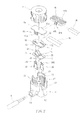
- a watertight junction box in accordance with the present invention comprises a box body 1, a lower floating plate 2, an upper floating plate 3, a holding down plate 4a or 4b and a lock cap 5.
- the box body 1 is a hollow member comprising a threaded neck 11, an opening 12 transversely cut through the threaded neck 11 to separate the threaded neck 11 into two symmetrical halves, an accommodation chamber 13 defined beneath the threaded neck 11 (see FIG. 2 and FIG. 3 ), an insertion hole 14 cut through one side of the accommodation chamber 13 for the insertion of a modular cable 6 into the accommodation chamber 13, a partition board 15 disposed inside the accommodation chamber 13 (see FIG. 3 and FIG. 4 ), two copper contacts 16 mounted in the accommodation chamber 13 at two sides relative to the partition board 15 and a plurality of ribs 17 located on the inside wall of each of the two symmetrical halves of the threaded neck 11.
- each copper contact 16 has a plurality of sharp top protrusions 161. After the modular cable 6 is inserted into the insertion hole 14, the copper contacts 16 are respectively forced with the bottom edges thereof into contact with the (conductors of the) modular cable 6, and then a resin glue 18 is filled in the accommodation chamber 13 so that the connection between the sharp copper contacts 16 and the modular cable 6 is embedded in the hardened resin glue 18 (see FIG. 6 ).
- the lower floating plate 2 is a flat plate having two through holes 21 for the copper contacts 16 to pass through, two bottom legs 22 diagonally disposed at the bottom side and two springy supporting strips 23 diagonally disposed at the top side.
- the lower floating plate 2 is inserted into the accommodation chamber 13 of the box body 1 (see FIG. 5 ), enabling the two bottom legs 22 to be embedded in the resin glue 18 (see FIG. 6 ).
- the upper floating plate 3 is a flat plate having two through holes 31 corresponding to the through holes 21 of the lower floating plate 2 for the copper contacts 16 to pass through and two notched side edges 32 fitting the ribs 17.
- the upper floating plate 3 is set inside the threaded neck 11 above the lower floating plate 2. Further, a suitable amount of silicon rubber 7 is filled in the accommodation chamber 13 in between the lower floating plate 2 and the upper floating plate 3 (see FIG. 6 ).
- the holding down plate 4a or 4b is selectively used depending upon the thickness of the external electric wire 8a or 8b to be connected.
- the holding down plate 4a or 4b is a flat clamping plate having a substantially-shaped cross section and a vertical groove 42a or 42b on each of the two opposite lateral sidewalls 41a or 41b thereof for receiving one of the ribs 17 at each of the two symmetrical halves of the threaded neck 11.
- the lock cap 5 is a screw cap for threading onto the threaded neck 11 of the box body 1, having an inside stop wall 51 that curves inwards (see FIG. 7 or FIG. 8 ).
- the box body 1, the lower floating plate 2, the upper floating plate 3, the holding down plate 4a or 4b and the lock cap 5 are assembled to form the desired watertight junction box.
- a certain amount of soft rubber, in particular silicon rubber 7 is filled in the accommodation chamber 13 in between the lower floating plate 2 and the upper floating plate 3.
- the external power wire 8a or 8b to be connected is set in opening 12 of the box body 1 and transversely extended through the threaded neck 11 and kept between the holding down plate 4a (or 4b) and the upper floating plate 3, and then the lock cap 5 is threaded onto the threaded neck 11 of the box body 1.
- the inside stop wall 51 is forced downwardly against the holding down plate 4a (or 4b), causing the sharp top protrusions 161 of the copper contacts 16 to pierce the outer insulation 81 a or 81 b of the external power wire 8a or 8b (see FIG. 8 or FIG. 10 ) and to contact the respective conductors in the external power wire 8a or 8b.
- the silicon rubber 7 is compressed to seal the contact area between the copper contacts 16 and the external power wire 8a or 8b (see FIG. 8 ), thereby protecting the copper contacts 16 against oxidation and corrosion and achieving excellent watertight sealing effects.
- the silicon rubber 7 is an elastic material that is able to return to its former shape after being pulled or pressed. After the external power wire 8a or 8b is removed, the silicon rubber 7 immediately returns to its former shape, filling up the space in the accommodation chamber 13 in between the lower floating plate 2 and the upper floating plate 3. Therefore, the watertight junction box of the present invention can be used repeatedly without lowering its watertight sealing function.
- the holding down plate 4a or 4b is selectively used depending upon the thickness of the external power wire 8a or 8b to be connected. These two holding down plates 4a and 4b have the same structural design with the exception of the gap width between the two opposite lateral sidewalls 41a or 41b. For example, FIG. 9 shows a thinner external power wire 8b installed in the watertight junction box.
- the modular cable 6 is an electrical cable having a modular connector, for example, modular jack 61 at its one end.
- the other end of the modular cable 6 is inserted through the insertion hole 14 into the accommodation chamber 13 with the two bare conductors separated by the partition board 15 and respectively held down in the accommodation chamber 13 by the copper contacts 16 and sealed by the resin glue 18. Due to the sealing effect of the resin glue 18, the connection between the copper contacts 16 and the modular cable 6 is assured.
- the box body 1 has two locating grooves 19 defined in the accommodation chamber 13 at two sides relative to the partition board 15 for receiving the copper contacts 16 respectively.
- the main feature of the present design is the filling of the silicon rubber 7 in the accommodation chamber 13.
- the silicon rubber 7 is compressed and deformed to protrude over the through holes 31 of the upper floating plate 3 and to wrap about the contact area between the copper contacts 16 and the conductors 82a or 82b of the external power wire 8a or 8b, thereby protecting the copper contacts 16 against oxidation and corrosion and achieving excellent watertight sealing effects. Therefore, the invention prolongs the work life of the junction box and assures conductive stability.
- one single-piece hollow member may be used to substitute for the lower floating plate 2 and the upper floating plate 3 for holding a suitable amount of silicon rubber 7 for allowing the silicon rubber 7 to be compressed and deformed to wrap about the connection area between the copper contacts and the conductors of the external power wire, achieving excellent watertight sealing effects.
- a watertight junction box including a box body 1, a lower floating plate 2, an upper floating plate 3, a lock cap 5, a modular cable 6 inserted into the box body 1 and kept in contact with sharp copper contacts 16.
- a holding down plate 4a or 4b for holding down an external power wire 8a or 8b on the upper floating plate 3 to cause electric contact between the external power wire 8a or 8b and the sharp copper contacts, 16 and a predetermined amount of silicon rubber 7 filled in between the lower and upper floating plate 3 that is deformed to wrap about the connection area between the sharp copper contacts 16 and the external power wire 8a or 8b when the lock cap 5 is tightly fastened to the box body 1 to force down the holding down plate 4a or 4b.
Landscapes
- Chemical & Material Sciences (AREA)
- Dispersion Chemistry (AREA)
- Connection Or Junction Boxes (AREA)
Priority Applications (1)
| Application Number | Priority Date | Filing Date | Title |
|---|---|---|---|
| EP09174991A EP2320523B1 (fr) | 2009-11-04 | 2009-11-04 | Boîtier de raccordement étanche à l'eau |
Applications Claiming Priority (1)
| Application Number | Priority Date | Filing Date | Title |
|---|---|---|---|
| EP09174991A EP2320523B1 (fr) | 2009-11-04 | 2009-11-04 | Boîtier de raccordement étanche à l'eau |
Publications (2)
| Publication Number | Publication Date |
|---|---|
| EP2320523A1 true EP2320523A1 (fr) | 2011-05-11 |
| EP2320523B1 EP2320523B1 (fr) | 2012-07-18 |
Family
ID=42027749
Family Applications (1)
| Application Number | Title | Priority Date | Filing Date |
|---|---|---|---|
| EP09174991A Active EP2320523B1 (fr) | 2009-11-04 | 2009-11-04 | Boîtier de raccordement étanche à l'eau |
Country Status (1)
| Country | Link |
|---|---|
| EP (1) | EP2320523B1 (fr) |
Cited By (3)
| Publication number | Priority date | Publication date | Assignee | Title |
|---|---|---|---|---|
| CN103259105A (zh) * | 2012-09-25 | 2013-08-21 | 优光环保材料(上海)有限公司 | 一种接线保护盒及其使用方法 |
| ITMI20121203A1 (it) * | 2012-07-10 | 2014-01-11 | Techno S R L | Struttura di morsetto preleva-corrente, a perforazione di isolante |
| WO2019203636A1 (fr) * | 2018-04-19 | 2019-10-24 | Buysman Holding B.V. | Connecteur de perçage |
Citations (5)
| Publication number | Priority date | Publication date | Assignee | Title |
|---|---|---|---|---|
| GB691802A (en) * | 1950-11-21 | 1953-05-20 | Communications Patents Ltd | Improved electric coupling devices |
| US4993966A (en) * | 1990-04-27 | 1991-02-19 | Thomas & Betts Corporation | Electrical connector block |
| US5499931A (en) | 1994-08-11 | 1996-03-19 | Yang; Jerry S. C. | Electrical-conducting structure of a lighting fixture |
| WO2001015276A1 (fr) * | 1999-08-24 | 2001-03-01 | Tappat Engineering Pty Limited | Connecteur perforateur pour cable electrique |
| WO2009059335A1 (fr) * | 2007-10-31 | 2009-05-07 | Detnet South Africa (Pty) Limited | Connecteur pour détonateur |
-
2009
- 2009-11-04 EP EP09174991A patent/EP2320523B1/fr active Active
Patent Citations (5)
| Publication number | Priority date | Publication date | Assignee | Title |
|---|---|---|---|---|
| GB691802A (en) * | 1950-11-21 | 1953-05-20 | Communications Patents Ltd | Improved electric coupling devices |
| US4993966A (en) * | 1990-04-27 | 1991-02-19 | Thomas & Betts Corporation | Electrical connector block |
| US5499931A (en) | 1994-08-11 | 1996-03-19 | Yang; Jerry S. C. | Electrical-conducting structure of a lighting fixture |
| WO2001015276A1 (fr) * | 1999-08-24 | 2001-03-01 | Tappat Engineering Pty Limited | Connecteur perforateur pour cable electrique |
| WO2009059335A1 (fr) * | 2007-10-31 | 2009-05-07 | Detnet South Africa (Pty) Limited | Connecteur pour détonateur |
Cited By (5)
| Publication number | Priority date | Publication date | Assignee | Title |
|---|---|---|---|---|
| ITMI20121203A1 (it) * | 2012-07-10 | 2014-01-11 | Techno S R L | Struttura di morsetto preleva-corrente, a perforazione di isolante |
| EP2685561A1 (fr) | 2012-07-10 | 2014-01-15 | TECHNO S.r.l. | Connecteur de dérivation avec contact autodénudant |
| CN103259105A (zh) * | 2012-09-25 | 2013-08-21 | 优光环保材料(上海)有限公司 | 一种接线保护盒及其使用方法 |
| WO2019203636A1 (fr) * | 2018-04-19 | 2019-10-24 | Buysman Holding B.V. | Connecteur de perçage |
| NL2020796B1 (en) * | 2018-04-19 | 2019-10-28 | Buysman Holding B V | Piercing connector |
Also Published As
| Publication number | Publication date |
|---|---|
| EP2320523B1 (fr) | 2012-07-18 |
Similar Documents
| Publication | Publication Date | Title |
|---|---|---|
| US8101874B2 (en) | Watertight junction box | |
| DK2458691T3 (en) | Partially embedded power supply unit and the process for preparing | |
| US3012219A (en) | Solderless connector for insulated small wires | |
| US8684761B2 (en) | Solar insulation displacement connector | |
| CA2668271A1 (fr) | Connecteur a double paroi | |
| JP2011060770A5 (fr) | ||
| KR20090099535A (ko) | 접속부재 및 하니스 접속체 | |
| US9450364B2 (en) | Tape light electrical connector | |
| JP2011096535A (ja) | 防水電線接続箱 | |
| EP2320523B1 (fr) | Boîtier de raccordement étanche à l'eau | |
| CA2684111C (fr) | Boite de jonction etanche | |
| CN100438215C (zh) | 对接及连接装置、相应的连接导线和插座元件 | |
| CN218004734U (zh) | 接触器低压模块和接触器 | |
| CN100340030C (zh) | 带有空心销钉的插头电桥以及用于插头电桥的空心销钉 | |
| CN207474744U (zh) | 一种电连接组件 | |
| CN207116749U (zh) | 连接器 | |
| CN203645008U (zh) | 接线端子 | |
| CN201663242U (zh) | 一种接线连接器 | |
| KR20120021167A (ko) | 단자 박스 | |
| CN202712451U (zh) | 快速接线夹 | |
| JP2014102932A (ja) | 電線端末の止水構造 | |
| CN206877957U (zh) | 手动维修开关 | |
| CN222072288U (zh) | 一种快速的防水接线装置 | |
| CN205141177U (zh) | 一种端子 | |
| CN221262735U (zh) | 一种用于灯饰轨道的快速接线端子及接线盒 |
Legal Events
| Date | Code | Title | Description |
|---|---|---|---|
| PUAI | Public reference made under article 153(3) epc to a published international application that has entered the european phase |
Free format text: ORIGINAL CODE: 0009012 |
|
| AK | Designated contracting states |
Kind code of ref document: A1 Designated state(s): AT BE BG CH CY CZ DE DK EE ES FI FR GB GR HR HU IE IS IT LI LT LU LV MC MK MT NL NO PL PT RO SE SI SK SM TR |
|
| AX | Request for extension of the european patent |
Extension state: AL BA RS |
|
| 17P | Request for examination filed |
Effective date: 20111012 |
|
| GRAP | Despatch of communication of intention to grant a patent |
Free format text: ORIGINAL CODE: EPIDOSNIGR1 |
|
| GRAS | Grant fee paid |
Free format text: ORIGINAL CODE: EPIDOSNIGR3 |
|
| GRAA | (expected) grant |
Free format text: ORIGINAL CODE: 0009210 |
|
| AK | Designated contracting states |
Kind code of ref document: B1 Designated state(s): AT BE BG CH CY CZ DE DK EE ES FI FR GB GR HR HU IE IS IT LI LT LU LV MC MK MT NL NO PL PT RO SE SI SK SM TR |
|
| REG | Reference to a national code |
Ref country code: GB Ref legal event code: FG4D |
|
| REG | Reference to a national code |
Ref country code: CH Ref legal event code: EP |
|
| REG | Reference to a national code |
Ref country code: AT Ref legal event code: REF Ref document number: 567222 Country of ref document: AT Kind code of ref document: T Effective date: 20120815 Ref country code: IE Ref legal event code: FG4D |
|
| REG | Reference to a national code |
Ref country code: DE Ref legal event code: R096 Ref document number: 602009008342 Country of ref document: DE Effective date: 20120913 |
|
| REG | Reference to a national code |
Ref country code: NL Ref legal event code: T3 |
|
| REG | Reference to a national code |
Ref country code: AT Ref legal event code: MK05 Ref document number: 567222 Country of ref document: AT Kind code of ref document: T Effective date: 20120718 |
|
| REG | Reference to a national code |
Ref country code: LT Ref legal event code: MG4D Effective date: 20120718 |
|
| PG25 | Lapsed in a contracting state [announced via postgrant information from national office to epo] |
Ref country code: NO Free format text: LAPSE BECAUSE OF FAILURE TO SUBMIT A TRANSLATION OF THE DESCRIPTION OR TO PAY THE FEE WITHIN THE PRESCRIBED TIME-LIMIT Effective date: 20121018 Ref country code: HR Free format text: LAPSE BECAUSE OF FAILURE TO SUBMIT A TRANSLATION OF THE DESCRIPTION OR TO PAY THE FEE WITHIN THE PRESCRIBED TIME-LIMIT Effective date: 20120718 Ref country code: FI Free format text: LAPSE BECAUSE OF FAILURE TO SUBMIT A TRANSLATION OF THE DESCRIPTION OR TO PAY THE FEE WITHIN THE PRESCRIBED TIME-LIMIT Effective date: 20120718 Ref country code: AT Free format text: LAPSE BECAUSE OF FAILURE TO SUBMIT A TRANSLATION OF THE DESCRIPTION OR TO PAY THE FEE WITHIN THE PRESCRIBED TIME-LIMIT Effective date: 20120718 Ref country code: LT Free format text: LAPSE BECAUSE OF FAILURE TO SUBMIT A TRANSLATION OF THE DESCRIPTION OR TO PAY THE FEE WITHIN THE PRESCRIBED TIME-LIMIT Effective date: 20120718 Ref country code: IS Free format text: LAPSE BECAUSE OF FAILURE TO SUBMIT A TRANSLATION OF THE DESCRIPTION OR TO PAY THE FEE WITHIN THE PRESCRIBED TIME-LIMIT Effective date: 20121118 Ref country code: CY Free format text: LAPSE BECAUSE OF FAILURE TO SUBMIT A TRANSLATION OF THE DESCRIPTION OR TO PAY THE FEE WITHIN THE PRESCRIBED TIME-LIMIT Effective date: 20120718 |
|
| PG25 | Lapsed in a contracting state [announced via postgrant information from national office to epo] |
Ref country code: SE Free format text: LAPSE BECAUSE OF FAILURE TO SUBMIT A TRANSLATION OF THE DESCRIPTION OR TO PAY THE FEE WITHIN THE PRESCRIBED TIME-LIMIT Effective date: 20120718 Ref country code: GR Free format text: LAPSE BECAUSE OF FAILURE TO SUBMIT A TRANSLATION OF THE DESCRIPTION OR TO PAY THE FEE WITHIN THE PRESCRIBED TIME-LIMIT Effective date: 20121019 Ref country code: PT Free format text: LAPSE BECAUSE OF FAILURE TO SUBMIT A TRANSLATION OF THE DESCRIPTION OR TO PAY THE FEE WITHIN THE PRESCRIBED TIME-LIMIT Effective date: 20121119 Ref country code: PL Free format text: LAPSE BECAUSE OF FAILURE TO SUBMIT A TRANSLATION OF THE DESCRIPTION OR TO PAY THE FEE WITHIN THE PRESCRIBED TIME-LIMIT Effective date: 20120718 Ref country code: LV Free format text: LAPSE BECAUSE OF FAILURE TO SUBMIT A TRANSLATION OF THE DESCRIPTION OR TO PAY THE FEE WITHIN THE PRESCRIBED TIME-LIMIT Effective date: 20120718 Ref country code: SI Free format text: LAPSE BECAUSE OF FAILURE TO SUBMIT A TRANSLATION OF THE DESCRIPTION OR TO PAY THE FEE WITHIN THE PRESCRIBED TIME-LIMIT Effective date: 20120718 |
|
| PG25 | Lapsed in a contracting state [announced via postgrant information from national office to epo] |
Ref country code: RO Free format text: LAPSE BECAUSE OF FAILURE TO SUBMIT A TRANSLATION OF THE DESCRIPTION OR TO PAY THE FEE WITHIN THE PRESCRIBED TIME-LIMIT Effective date: 20120718 Ref country code: CZ Free format text: LAPSE BECAUSE OF FAILURE TO SUBMIT A TRANSLATION OF THE DESCRIPTION OR TO PAY THE FEE WITHIN THE PRESCRIBED TIME-LIMIT Effective date: 20120718 Ref country code: EE Free format text: LAPSE BECAUSE OF FAILURE TO SUBMIT A TRANSLATION OF THE DESCRIPTION OR TO PAY THE FEE WITHIN THE PRESCRIBED TIME-LIMIT Effective date: 20120718 Ref country code: DK Free format text: LAPSE BECAUSE OF FAILURE TO SUBMIT A TRANSLATION OF THE DESCRIPTION OR TO PAY THE FEE WITHIN THE PRESCRIBED TIME-LIMIT Effective date: 20120718 Ref country code: ES Free format text: LAPSE BECAUSE OF FAILURE TO SUBMIT A TRANSLATION OF THE DESCRIPTION OR TO PAY THE FEE WITHIN THE PRESCRIBED TIME-LIMIT Effective date: 20121029 |
|
| PLBE | No opposition filed within time limit |
Free format text: ORIGINAL CODE: 0009261 |
|
| STAA | Information on the status of an ep patent application or granted ep patent |
Free format text: STATUS: NO OPPOSITION FILED WITHIN TIME LIMIT |
|
| PG25 | Lapsed in a contracting state [announced via postgrant information from national office to epo] |
Ref country code: IT Free format text: LAPSE BECAUSE OF FAILURE TO SUBMIT A TRANSLATION OF THE DESCRIPTION OR TO PAY THE FEE WITHIN THE PRESCRIBED TIME-LIMIT Effective date: 20120718 Ref country code: SK Free format text: LAPSE BECAUSE OF FAILURE TO SUBMIT A TRANSLATION OF THE DESCRIPTION OR TO PAY THE FEE WITHIN THE PRESCRIBED TIME-LIMIT Effective date: 20120718 |
|
| 26N | No opposition filed |
Effective date: 20130419 |
|
| PG25 | Lapsed in a contracting state [announced via postgrant information from national office to epo] |
Ref country code: BG Free format text: LAPSE BECAUSE OF FAILURE TO SUBMIT A TRANSLATION OF THE DESCRIPTION OR TO PAY THE FEE WITHIN THE PRESCRIBED TIME-LIMIT Effective date: 20121018 |
|
| REG | Reference to a national code |
Ref country code: DE Ref legal event code: R097 Ref document number: 602009008342 Country of ref document: DE Effective date: 20130419 Ref country code: IE Ref legal event code: MM4A |
|
| PG25 | Lapsed in a contracting state [announced via postgrant information from national office to epo] |
Ref country code: IE Free format text: LAPSE BECAUSE OF NON-PAYMENT OF DUE FEES Effective date: 20121104 |
|
| PG25 | Lapsed in a contracting state [announced via postgrant information from national office to epo] |
Ref country code: MT Free format text: LAPSE BECAUSE OF FAILURE TO SUBMIT A TRANSLATION OF THE DESCRIPTION OR TO PAY THE FEE WITHIN THE PRESCRIBED TIME-LIMIT Effective date: 20120718 |
|
| PG25 | Lapsed in a contracting state [announced via postgrant information from national office to epo] |
Ref country code: MC Free format text: LAPSE BECAUSE OF NON-PAYMENT OF DUE FEES Effective date: 20121130 Ref country code: TR Free format text: LAPSE BECAUSE OF FAILURE TO SUBMIT A TRANSLATION OF THE DESCRIPTION OR TO PAY THE FEE WITHIN THE PRESCRIBED TIME-LIMIT Effective date: 20120718 |
|
| PG25 | Lapsed in a contracting state [announced via postgrant information from national office to epo] |
Ref country code: LU Free format text: LAPSE BECAUSE OF NON-PAYMENT OF DUE FEES Effective date: 20121104 Ref country code: SM Free format text: LAPSE BECAUSE OF FAILURE TO SUBMIT A TRANSLATION OF THE DESCRIPTION OR TO PAY THE FEE WITHIN THE PRESCRIBED TIME-LIMIT Effective date: 20120718 |
|
| REG | Reference to a national code |
Ref country code: CH Ref legal event code: PL |
|
| PG25 | Lapsed in a contracting state [announced via postgrant information from national office to epo] |
Ref country code: LI Free format text: LAPSE BECAUSE OF NON-PAYMENT OF DUE FEES Effective date: 20131130 Ref country code: HU Free format text: LAPSE BECAUSE OF FAILURE TO SUBMIT A TRANSLATION OF THE DESCRIPTION OR TO PAY THE FEE WITHIN THE PRESCRIBED TIME-LIMIT Effective date: 20091104 Ref country code: CH Free format text: LAPSE BECAUSE OF NON-PAYMENT OF DUE FEES Effective date: 20131130 |
|
| PG25 | Lapsed in a contracting state [announced via postgrant information from national office to epo] |
Ref country code: MK Free format text: LAPSE BECAUSE OF FAILURE TO SUBMIT A TRANSLATION OF THE DESCRIPTION OR TO PAY THE FEE WITHIN THE PRESCRIBED TIME-LIMIT Effective date: 20120718 |
|
| REG | Reference to a national code |
Ref country code: FR Ref legal event code: PLFP Year of fee payment: 7 |
|
| REG | Reference to a national code |
Ref country code: FR Ref legal event code: PLFP Year of fee payment: 8 |
|
| REG | Reference to a national code |
Ref country code: FR Ref legal event code: PLFP Year of fee payment: 9 |
|
| PGFP | Annual fee paid to national office [announced via postgrant information from national office to epo] |
Ref country code: NL Payment date: 20251119 Year of fee payment: 17 |
|
| PGFP | Annual fee paid to national office [announced via postgrant information from national office to epo] |
Ref country code: DE Payment date: 20251128 Year of fee payment: 17 |
|
| PGFP | Annual fee paid to national office [announced via postgrant information from national office to epo] |
Ref country code: GB Payment date: 20251128 Year of fee payment: 17 |
|
| PGFP | Annual fee paid to national office [announced via postgrant information from national office to epo] |
Ref country code: FR Payment date: 20251128 Year of fee payment: 17 |
|
| PGFP | Annual fee paid to national office [announced via postgrant information from national office to epo] |
Ref country code: BE Payment date: 20251118 Year of fee payment: 17 |