EP2320659B1 - Codierungsverfahren und Decodierungsverfahren für bewegliche Bilder - Google Patents
Codierungsverfahren und Decodierungsverfahren für bewegliche Bilder Download PDFInfo
- Publication number
- EP2320659B1 EP2320659B1 EP10178507.9A EP10178507A EP2320659B1 EP 2320659 B1 EP2320659 B1 EP 2320659B1 EP 10178507 A EP10178507 A EP 10178507A EP 2320659 B1 EP2320659 B1 EP 2320659B1
- Authority
- EP
- European Patent Office
- Prior art keywords
- picture
- linear prediction
- coded
- equation
- predictive image
- Prior art date
- Legal status (The legal status is an assumption and is not a legal conclusion. Google has not performed a legal analysis and makes no representation as to the accuracy of the status listed.)
- Expired - Lifetime
Links
- 238000000034 method Methods 0.000 title claims description 227
- 238000012545 processing Methods 0.000 description 106
- 238000010586 diagram Methods 0.000 description 75
- 238000004364 calculation method Methods 0.000 description 64
- 238000004458 analytical method Methods 0.000 description 27
- 238000007796 conventional method Methods 0.000 description 22
- 238000007792 addition Methods 0.000 description 14
- 238000006243 chemical reaction Methods 0.000 description 13
- 239000013598 vector Substances 0.000 description 12
- 230000009467 reduction Effects 0.000 description 11
- 230000002123 temporal effect Effects 0.000 description 11
- 230000008859 change Effects 0.000 description 9
- 239000000872 buffer Substances 0.000 description 8
- 230000008569 process Effects 0.000 description 8
- 238000004891 communication Methods 0.000 description 6
- 101000575029 Bacillus subtilis (strain 168) 50S ribosomal protein L11 Proteins 0.000 description 5
- 102100035793 CD83 antigen Human genes 0.000 description 5
- 101000946856 Homo sapiens CD83 antigen Proteins 0.000 description 5
- 238000001228 spectrum Methods 0.000 description 5
- 230000008901 benefit Effects 0.000 description 4
- 230000005540 biological transmission Effects 0.000 description 4
- 101001070329 Geobacillus stearothermophilus 50S ribosomal protein L18 Proteins 0.000 description 3
- 230000006835 compression Effects 0.000 description 3
- 238000007906 compression Methods 0.000 description 3
- 230000000694 effects Effects 0.000 description 3
- 239000000284 extract Substances 0.000 description 3
- 230000006872 improvement Effects 0.000 description 3
- 238000013139 quantization Methods 0.000 description 3
- 238000013459 approach Methods 0.000 description 2
- 238000013213 extrapolation Methods 0.000 description 2
- 230000006870 function Effects 0.000 description 2
- 239000004973 liquid crystal related substance Substances 0.000 description 2
- 230000007774 longterm Effects 0.000 description 2
- 230000003287 optical effect Effects 0.000 description 2
- 230000000750 progressive effect Effects 0.000 description 2
- 230000002441 reversible effect Effects 0.000 description 2
- 230000001360 synchronised effect Effects 0.000 description 2
- 230000009466 transformation Effects 0.000 description 2
- 238000012935 Averaging Methods 0.000 description 1
- 238000011161 development Methods 0.000 description 1
- 238000005516 engineering process Methods 0.000 description 1
- 230000007274 generation of a signal involved in cell-cell signaling Effects 0.000 description 1
- 238000013507 mapping Methods 0.000 description 1
- 238000010295 mobile communication Methods 0.000 description 1
- 230000008520 organization Effects 0.000 description 1
- 230000011664 signaling Effects 0.000 description 1
Images











Classifications
-
- H—ELECTRICITY
- H04—ELECTRIC COMMUNICATION TECHNIQUE
- H04N—PICTORIAL COMMUNICATION, e.g. TELEVISION
- H04N19/00—Methods or arrangements for coding, decoding, compressing or decompressing digital video signals
- H04N19/10—Methods or arrangements for coding, decoding, compressing or decompressing digital video signals using adaptive coding
- H04N19/102—Methods or arrangements for coding, decoding, compressing or decompressing digital video signals using adaptive coding characterised by the element, parameter or selection affected or controlled by the adaptive coding
- H04N19/103—Selection of coding mode or of prediction mode
- H04N19/105—Selection of the reference unit for prediction within a chosen coding or prediction mode, e.g. adaptive choice of position and number of pixels used for prediction
-
- H—ELECTRICITY
- H04—ELECTRIC COMMUNICATION TECHNIQUE
- H04N—PICTORIAL COMMUNICATION, e.g. TELEVISION
- H04N19/00—Methods or arrangements for coding, decoding, compressing or decompressing digital video signals
- H04N19/10—Methods or arrangements for coding, decoding, compressing or decompressing digital video signals using adaptive coding
- H04N19/102—Methods or arrangements for coding, decoding, compressing or decompressing digital video signals using adaptive coding characterised by the element, parameter or selection affected or controlled by the adaptive coding
- H04N19/103—Selection of coding mode or of prediction mode
-
- H—ELECTRICITY
- H04—ELECTRIC COMMUNICATION TECHNIQUE
- H04N—PICTORIAL COMMUNICATION, e.g. TELEVISION
- H04N19/00—Methods or arrangements for coding, decoding, compressing or decompressing digital video signals
- H04N19/10—Methods or arrangements for coding, decoding, compressing or decompressing digital video signals using adaptive coding
- H04N19/102—Methods or arrangements for coding, decoding, compressing or decompressing digital video signals using adaptive coding characterised by the element, parameter or selection affected or controlled by the adaptive coding
- H04N19/117—Filters, e.g. for pre-processing or post-processing
-
- H—ELECTRICITY
- H04—ELECTRIC COMMUNICATION TECHNIQUE
- H04N—PICTORIAL COMMUNICATION, e.g. TELEVISION
- H04N19/00—Methods or arrangements for coding, decoding, compressing or decompressing digital video signals
- H04N19/10—Methods or arrangements for coding, decoding, compressing or decompressing digital video signals using adaptive coding
- H04N19/134—Methods or arrangements for coding, decoding, compressing or decompressing digital video signals using adaptive coding characterised by the element, parameter or criterion affecting or controlling the adaptive coding
-
- H—ELECTRICITY
- H04—ELECTRIC COMMUNICATION TECHNIQUE
- H04N—PICTORIAL COMMUNICATION, e.g. TELEVISION
- H04N19/00—Methods or arrangements for coding, decoding, compressing or decompressing digital video signals
- H04N19/10—Methods or arrangements for coding, decoding, compressing or decompressing digital video signals using adaptive coding
- H04N19/134—Methods or arrangements for coding, decoding, compressing or decompressing digital video signals using adaptive coding characterised by the element, parameter or criterion affecting or controlling the adaptive coding
- H04N19/136—Incoming video signal characteristics or properties
- H04N19/137—Motion inside a coding unit, e.g. average field, frame or block difference
-
- H—ELECTRICITY
- H04—ELECTRIC COMMUNICATION TECHNIQUE
- H04N—PICTORIAL COMMUNICATION, e.g. TELEVISION
- H04N19/00—Methods or arrangements for coding, decoding, compressing or decompressing digital video signals
- H04N19/10—Methods or arrangements for coding, decoding, compressing or decompressing digital video signals using adaptive coding
- H04N19/134—Methods or arrangements for coding, decoding, compressing or decompressing digital video signals using adaptive coding characterised by the element, parameter or criterion affecting or controlling the adaptive coding
- H04N19/136—Incoming video signal characteristics or properties
- H04N19/137—Motion inside a coding unit, e.g. average field, frame or block difference
- H04N19/139—Analysis of motion vectors, e.g. their magnitude, direction, variance or reliability
-
- H—ELECTRICITY
- H04—ELECTRIC COMMUNICATION TECHNIQUE
- H04N—PICTORIAL COMMUNICATION, e.g. TELEVISION
- H04N19/00—Methods or arrangements for coding, decoding, compressing or decompressing digital video signals
- H04N19/10—Methods or arrangements for coding, decoding, compressing or decompressing digital video signals using adaptive coding
- H04N19/134—Methods or arrangements for coding, decoding, compressing or decompressing digital video signals using adaptive coding characterised by the element, parameter or criterion affecting or controlling the adaptive coding
- H04N19/146—Data rate or code amount at the encoder output
- H04N19/147—Data rate or code amount at the encoder output according to rate distortion criteria
-
- H—ELECTRICITY
- H04—ELECTRIC COMMUNICATION TECHNIQUE
- H04N—PICTORIAL COMMUNICATION, e.g. TELEVISION
- H04N19/00—Methods or arrangements for coding, decoding, compressing or decompressing digital video signals
- H04N19/10—Methods or arrangements for coding, decoding, compressing or decompressing digital video signals using adaptive coding
- H04N19/134—Methods or arrangements for coding, decoding, compressing or decompressing digital video signals using adaptive coding characterised by the element, parameter or criterion affecting or controlling the adaptive coding
- H04N19/157—Assigned coding mode, i.e. the coding mode being predefined or preselected to be further used for selection of another element or parameter
- H04N19/159—Prediction type, e.g. intra-frame, inter-frame or bidirectional frame prediction
-
- H—ELECTRICITY
- H04—ELECTRIC COMMUNICATION TECHNIQUE
- H04N—PICTORIAL COMMUNICATION, e.g. TELEVISION
- H04N19/00—Methods or arrangements for coding, decoding, compressing or decompressing digital video signals
- H04N19/10—Methods or arrangements for coding, decoding, compressing or decompressing digital video signals using adaptive coding
- H04N19/169—Methods or arrangements for coding, decoding, compressing or decompressing digital video signals using adaptive coding characterised by the coding unit, i.e. the structural portion or semantic portion of the video signal being the object or the subject of the adaptive coding
- H04N19/17—Methods or arrangements for coding, decoding, compressing or decompressing digital video signals using adaptive coding characterised by the coding unit, i.e. the structural portion or semantic portion of the video signal being the object or the subject of the adaptive coding the unit being an image region, e.g. an object
- H04N19/172—Methods or arrangements for coding, decoding, compressing or decompressing digital video signals using adaptive coding characterised by the coding unit, i.e. the structural portion or semantic portion of the video signal being the object or the subject of the adaptive coding the unit being an image region, e.g. an object the region being a picture, frame or field
-
- H—ELECTRICITY
- H04—ELECTRIC COMMUNICATION TECHNIQUE
- H04N—PICTORIAL COMMUNICATION, e.g. TELEVISION
- H04N19/00—Methods or arrangements for coding, decoding, compressing or decompressing digital video signals
- H04N19/10—Methods or arrangements for coding, decoding, compressing or decompressing digital video signals using adaptive coding
- H04N19/169—Methods or arrangements for coding, decoding, compressing or decompressing digital video signals using adaptive coding characterised by the coding unit, i.e. the structural portion or semantic portion of the video signal being the object or the subject of the adaptive coding
- H04N19/17—Methods or arrangements for coding, decoding, compressing or decompressing digital video signals using adaptive coding characterised by the coding unit, i.e. the structural portion or semantic portion of the video signal being the object or the subject of the adaptive coding the unit being an image region, e.g. an object
- H04N19/174—Methods or arrangements for coding, decoding, compressing or decompressing digital video signals using adaptive coding characterised by the coding unit, i.e. the structural portion or semantic portion of the video signal being the object or the subject of the adaptive coding the unit being an image region, e.g. an object the region being a slice, e.g. a line of blocks or a group of blocks
-
- H—ELECTRICITY
- H04—ELECTRIC COMMUNICATION TECHNIQUE
- H04N—PICTORIAL COMMUNICATION, e.g. TELEVISION
- H04N19/00—Methods or arrangements for coding, decoding, compressing or decompressing digital video signals
- H04N19/10—Methods or arrangements for coding, decoding, compressing or decompressing digital video signals using adaptive coding
- H04N19/169—Methods or arrangements for coding, decoding, compressing or decompressing digital video signals using adaptive coding characterised by the coding unit, i.e. the structural portion or semantic portion of the video signal being the object or the subject of the adaptive coding
- H04N19/17—Methods or arrangements for coding, decoding, compressing or decompressing digital video signals using adaptive coding characterised by the coding unit, i.e. the structural portion or semantic portion of the video signal being the object or the subject of the adaptive coding the unit being an image region, e.g. an object
- H04N19/176—Methods or arrangements for coding, decoding, compressing or decompressing digital video signals using adaptive coding characterised by the coding unit, i.e. the structural portion or semantic portion of the video signal being the object or the subject of the adaptive coding the unit being an image region, e.g. an object the region being a block, e.g. a macroblock
-
- H—ELECTRICITY
- H04—ELECTRIC COMMUNICATION TECHNIQUE
- H04N—PICTORIAL COMMUNICATION, e.g. TELEVISION
- H04N19/00—Methods or arrangements for coding, decoding, compressing or decompressing digital video signals
- H04N19/10—Methods or arrangements for coding, decoding, compressing or decompressing digital video signals using adaptive coding
- H04N19/169—Methods or arrangements for coding, decoding, compressing or decompressing digital video signals using adaptive coding characterised by the coding unit, i.e. the structural portion or semantic portion of the video signal being the object or the subject of the adaptive coding
- H04N19/177—Methods or arrangements for coding, decoding, compressing or decompressing digital video signals using adaptive coding characterised by the coding unit, i.e. the structural portion or semantic portion of the video signal being the object or the subject of the adaptive coding the unit being a group of pictures [GOP]
-
- H—ELECTRICITY
- H04—ELECTRIC COMMUNICATION TECHNIQUE
- H04N—PICTORIAL COMMUNICATION, e.g. TELEVISION
- H04N19/00—Methods or arrangements for coding, decoding, compressing or decompressing digital video signals
- H04N19/10—Methods or arrangements for coding, decoding, compressing or decompressing digital video signals using adaptive coding
- H04N19/169—Methods or arrangements for coding, decoding, compressing or decompressing digital video signals using adaptive coding characterised by the coding unit, i.e. the structural portion or semantic portion of the video signal being the object or the subject of the adaptive coding
- H04N19/18—Methods or arrangements for coding, decoding, compressing or decompressing digital video signals using adaptive coding characterised by the coding unit, i.e. the structural portion or semantic portion of the video signal being the object or the subject of the adaptive coding the unit being a set of transform coefficients
-
- H—ELECTRICITY
- H04—ELECTRIC COMMUNICATION TECHNIQUE
- H04N—PICTORIAL COMMUNICATION, e.g. TELEVISION
- H04N19/00—Methods or arrangements for coding, decoding, compressing or decompressing digital video signals
- H04N19/10—Methods or arrangements for coding, decoding, compressing or decompressing digital video signals using adaptive coding
- H04N19/169—Methods or arrangements for coding, decoding, compressing or decompressing digital video signals using adaptive coding characterised by the coding unit, i.e. the structural portion or semantic portion of the video signal being the object or the subject of the adaptive coding
- H04N19/182—Methods or arrangements for coding, decoding, compressing or decompressing digital video signals using adaptive coding characterised by the coding unit, i.e. the structural portion or semantic portion of the video signal being the object or the subject of the adaptive coding the unit being a pixel
-
- H—ELECTRICITY
- H04—ELECTRIC COMMUNICATION TECHNIQUE
- H04N—PICTORIAL COMMUNICATION, e.g. TELEVISION
- H04N19/00—Methods or arrangements for coding, decoding, compressing or decompressing digital video signals
- H04N19/42—Methods or arrangements for coding, decoding, compressing or decompressing digital video signals characterised by implementation details or hardware specially adapted for video compression or decompression, e.g. dedicated software implementation
-
- H—ELECTRICITY
- H04—ELECTRIC COMMUNICATION TECHNIQUE
- H04N—PICTORIAL COMMUNICATION, e.g. TELEVISION
- H04N19/00—Methods or arrangements for coding, decoding, compressing or decompressing digital video signals
- H04N19/46—Embedding additional information in the video signal during the compression process
-
- H—ELECTRICITY
- H04—ELECTRIC COMMUNICATION TECHNIQUE
- H04N—PICTORIAL COMMUNICATION, e.g. TELEVISION
- H04N19/00—Methods or arrangements for coding, decoding, compressing or decompressing digital video signals
- H04N19/50—Methods or arrangements for coding, decoding, compressing or decompressing digital video signals using predictive coding
- H04N19/503—Methods or arrangements for coding, decoding, compressing or decompressing digital video signals using predictive coding involving temporal prediction
- H04N19/51—Motion estimation or motion compensation
-
- H—ELECTRICITY
- H04—ELECTRIC COMMUNICATION TECHNIQUE
- H04N—PICTORIAL COMMUNICATION, e.g. TELEVISION
- H04N19/00—Methods or arrangements for coding, decoding, compressing or decompressing digital video signals
- H04N19/50—Methods or arrangements for coding, decoding, compressing or decompressing digital video signals using predictive coding
- H04N19/503—Methods or arrangements for coding, decoding, compressing or decompressing digital video signals using predictive coding involving temporal prediction
- H04N19/51—Motion estimation or motion compensation
- H04N19/573—Motion compensation with multiple frame prediction using two or more reference frames in a given prediction direction
-
- H—ELECTRICITY
- H04—ELECTRIC COMMUNICATION TECHNIQUE
- H04N—PICTORIAL COMMUNICATION, e.g. TELEVISION
- H04N19/00—Methods or arrangements for coding, decoding, compressing or decompressing digital video signals
- H04N19/50—Methods or arrangements for coding, decoding, compressing or decompressing digital video signals using predictive coding
- H04N19/503—Methods or arrangements for coding, decoding, compressing or decompressing digital video signals using predictive coding involving temporal prediction
- H04N19/51—Motion estimation or motion compensation
- H04N19/577—Motion compensation with bidirectional frame interpolation, i.e. using B-pictures
-
- H—ELECTRICITY
- H04—ELECTRIC COMMUNICATION TECHNIQUE
- H04N—PICTORIAL COMMUNICATION, e.g. TELEVISION
- H04N19/00—Methods or arrangements for coding, decoding, compressing or decompressing digital video signals
- H04N19/50—Methods or arrangements for coding, decoding, compressing or decompressing digital video signals using predictive coding
- H04N19/503—Methods or arrangements for coding, decoding, compressing or decompressing digital video signals using predictive coding involving temporal prediction
- H04N19/51—Motion estimation or motion compensation
- H04N19/58—Motion compensation with long-term prediction, i.e. the reference frame for a current frame not being the temporally closest one
-
- H—ELECTRICITY
- H04—ELECTRIC COMMUNICATION TECHNIQUE
- H04N—PICTORIAL COMMUNICATION, e.g. TELEVISION
- H04N19/00—Methods or arrangements for coding, decoding, compressing or decompressing digital video signals
- H04N19/50—Methods or arrangements for coding, decoding, compressing or decompressing digital video signals using predictive coding
- H04N19/593—Methods or arrangements for coding, decoding, compressing or decompressing digital video signals using predictive coding involving spatial prediction techniques
-
- H—ELECTRICITY
- H04—ELECTRIC COMMUNICATION TECHNIQUE
- H04N—PICTORIAL COMMUNICATION, e.g. TELEVISION
- H04N19/00—Methods or arrangements for coding, decoding, compressing or decompressing digital video signals
- H04N19/60—Methods or arrangements for coding, decoding, compressing or decompressing digital video signals using transform coding
- H04N19/61—Methods or arrangements for coding, decoding, compressing or decompressing digital video signals using transform coding in combination with predictive coding
-
- H—ELECTRICITY
- H04—ELECTRIC COMMUNICATION TECHNIQUE
- H04N—PICTORIAL COMMUNICATION, e.g. TELEVISION
- H04N19/00—Methods or arrangements for coding, decoding, compressing or decompressing digital video signals
- H04N19/70—Methods or arrangements for coding, decoding, compressing or decompressing digital video signals characterised by syntax aspects related to video coding, e.g. related to compression standards
Definitions
- the present invention relates to a moving picture coding method and a moving picture decoding method, and particularly to a coding method and a decoding method using inter-picture prediction with reference to previously coded pictures.
- inter-picture prediction coding which aims at reducing the temporal redundancy, motion of a current picture is estimated on a block-by-block basis with reference to preceding or subsequent pictures so as to create a predictive image, and then differential values between the obtained predictive images and the current picture are coded.
- the term "picture” represents a single sheet of an image, and it represents a frame when used in a context of a progressive image, whereas it represents a frame or a field in a context of an interlaced image.
- the interlaced image here is a single frame that is made up of two fields having different times respectively.
- a single frame can be handled as a frame, as two fields, or as a frame structure or a field structure on every block in the frame.
- FIG. 30 is a diagram for explaining types of pictures and reference relations between them.
- B-pictures can refer to two pictures located in arbitrary temporal directions.
- Reference pictures can be designated on a block-by-block basis, on which motion is estimated, and they are discriminated between a first reference picture which is described earlier in a coded stream obtained by coding pictures and a second reference picture which is described later in the coded stream.
- FIGs. 31A and 31B show examples of order of coding and decoding B-pictures.
- FIG. 31A shows a display order of the pictures
- FIG. 31B shows a coding and decoding order reordered from the display order as shown in FIG. 31A .
- These diagrams show that the pictures are reordered so that the pictures which are referred to by the pictures B3 and B6 are previously coded and decoded.
- a method for creating a predictive image in the case where the above-mentioned B-picture is coded with reference to two pictures at the same time will be explained in detail using FIG. 32 . Note that a predictive image is created in decoding in exactly the same manner.
- the picture B4 is a current B-picture to be coded, and blocks BL01 and BL02 are current blocks to be coded belonging to the current B-picture.
- a predictive image for the block BL01 is created.
- a block BL12 belonging to the picture P2 as a first reference picture and a block BL22 belonging to the picture P1 as a second reference picture a predictive image for the block BL02 is created (See Non-patent document 1).
- FIG. 33 is a diagram for explaining a method for creating a predictive image for the current block to be coded BL01 using the referred two blocks BL11 and BL21.
- a size of each block is 4 by 4 pixels.
- Q1(i) is a pixel value of BL11
- Q2(i) is a pixel value of BL21
- P(i) is a pixel value of the predictive image for the target BL01
- the pixel value P(i) can be calculated by a linear prediction equation like the following equation 1.
- "i" indicates the position of a pixel, and in this example, "i" has values of 0 to 15.
- weighting coefficient set is determined by a reference index designating a picture referred to by each block. For example, four values of w1_1, w2_1, c_1 and d_1 are used for BL01, and w1_2, w2_2, c_2 and d_2 are used for BL02, respectively.
- a value referred to as a picture number which increases one by one every time a picture is stored in a memory, is assigned to each picture.
- a picture number with a value added one to the maximum value of the existing picture numbers is assigned to a newly stored picture.
- a reference picture is not actually designated using this picture number, but using a value referred to as a reference index which is defined separately.
- Indices indicating first reference pictures are referred to as first reference indices
- indices indicating second reference pictures are referred to as second reference indices, respectively.
- FIG. 34 is a diagram for explaining a method for assigning two reference indices to picture numbers.
- picture numbers are assigned in coding order.
- Commands for assigning the reference indices to the picture numbers are described in a header of a slice that is a subdivision of a picture, as the unit of coding, and thus the assignment thereof are updated every time one slice is coded.
- the command indicates the differential value between a picture number assigned a reference index currently and a picture number assigned a reference index immediately before the current assignment, in series by the number of reference indices.
- FIG. 35 shows the result of the assignment of the reference indices.
- the first reference indices and the second reference indices are assigned to respective picture numbers separately, but focusing attention to each reference index, it is obvious that one reference index is assigned to one picture number.
- a coded stream of one picture is made up of a picture common information area and a plurality of slice data areas.
- FIG. 36 shows a structure of one slice data area among them.
- the slice data area is made up of a slice header area and a plurality of block data areas.
- block areas corresponding to BL01 and BL02 in FIG. 32 are shown here.
- FIG. 37 shows tables of the above-mentioned data included in the slice header area as an example.
- Each data indicated by an identifier "pset" has four values, w1, w2, c and d, and is structured so as to be directly referred to by the values of ref1 and ref2. Also, in the slice header area, a command sequence idx_cmd1 and idx_cmd2 for assigning the reference indices to the picture numbers are described.
- one set of weighting coefficients is selected from the table for ref1 and another set of them is selected from the table for ref2.
- two predictive images are generated.
- a desired predictive image can be obtained by averaging these two predictive images on a per-pixel basis.
- this method has the advantage that there is no need to code and transmit the weighting coefficient sets to obtain the predictive image because the prediction equation is fixed.
- This method has another advantage that there is no need to code and transmit a flag for designating the weighting coefficient sets of linear prediction coefficients because the fixed equation is selected based on the positional relationship between pictures.
- this method allows significant reduction of an amount of processing for linear prediction because of a simple formula for linear prediction.
- WO 01/86960 A2 discloses a system for video encoding and decoding that uses short-term and long-term buffers. Reconstruction of each block within an image may be performed with reference to one of the buffers, so that different portions of an image, or different images in a sequence, may be reconstructed using different buffers.
- the encoder may, for example, transmit information identifying video data as corresponding to a particular one of the buffers; and the decoder may transit information relating to the size of the short-term and the long-term buffer.
- the buffer sizes may be changed during transmission of vide data by including buffer allocation information in the video data. Also disclosed herein are methods and apparatuses according to the above.
- the picture coding method according to the present invention includes: a reference picture storage step of storing a coded picture identified by a picture number, as a reference picture, into a storage unit; a command generation step of generating commands indicating correspondence between reference indices and picture numbers, said reference indices designating reference pictures and coefficients used for generation of predictive images; a reference picture designation step of designating a reference picture by a reference index, said reference picture being used when motion compensation is performed on a current block in a current picture to be coded; a predictive image generation step of generating a predictive image by performing linear prediction on a block by use of a coefficient corresponding to the reference index, said block being obtained by motion estimation within the reference picture designated in the reference picture designation step; and a coded signal output step of outputting a coded image signal including a coded signal obtained by coding a prediction error, the commands, the reference index and the coefficient, said prediction error being a difference between the
- the commands are generated so that at least one reference picture, among reference pictures stored in the storage unit, has a picture number assigned a plurality of reference indices.
- the linear prediction is performed using only a bit shift operation, an addition and a subtraction.
- the reference index has a first reference index indicating a first reference picture and a second reference index indicating a second reference picture
- the predictive image generation step in the case where a method for generating the coefficient according to display order information of each of the reference pictures is used as a method for performing the linear prediction, when a reference picture designated by the first reference index and a reference picture designated by the second reference index have the same display order information, the linear prediction is performed using a predetermined coefficient for each of the first and second reference indices instead of the coefficient.
- it may be structured so that the predetermined coefficients have the same weight.
- the picture decoding method, the picture coding apparatus, the picture decoding apparatus, the picture coding program, the picture decoding program, and the coded picture data of the present invention have the same structures, functions and effects as the picture coding method described above.
- picture coding method of the present invention can be structured in any of the following manners (1) to (14).
- the moving picture coding method and the moving picture decoding method of the present invention allow creation of a plurality of candidates for weighting coefficient sets used in linear prediction for generating a predictive image, and thus allow selection of the optimum set for each block.
- the reference indices can be decoded more efficiently in either case where a plurality of reference indices are assigned or one reference index is assigned.
- the present invention allows significant improvement of coding efficiency, it is very effective for coding and decoding of moving pictures.
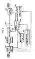
- FIG. 1 is a block diagram showing a structure of a moving picture coding apparatus in the first embodiment of the present invention.
- the moving picture coding method executed in this moving picture coding apparatus specifically, (1) an overview of coding, (2) a method for assigning reference indices and (3) a method for generating a predictive image, will be explained in this order using the block diagram as shown in FIG. 1 .
- FIGs. 31A and 31B are diagrams showing an example of reordering of pictures.
- FIG. 31A shows an example of pictures in display order
- FIG. 31B shows an example of the pictures reordered into coding order.
- pictures B3 and B6 refer both temporally preceding and subsequent pictures
- the reference pictures need to be coded before coding these current pictures and thus the pictures are reordered in FIG. 31B so that pictures P4 and P7 are coded earlier.
- Each of the pictures is divided into blocks, each of which is called a macroblock of horizontal 16 by vertical 16 pixels, for example, and the following proceeding is performed on a block-by-block basis.
- An input image signal read out from the picture memory 101 is inputted to a difference calculation unit 112.
- the difference calculation unit 112 calculates a difference between the input image signal and the predictive image signal outputted from a motion compensation coding unit 107, and outputs the obtained difference image signal (prediction error signal) to a prediction error coding unit 102.
- the prediction error coding unit 102 performs image coding processing such as frequency transformation and quantization, and outputs a coded error signal.
- the coded error signal is inputted to a prediction error decoding unit 104, which performs image decoding processing such as inverse-quantization and inverse-frequency transformation, and outputs a decoded error signal.
- An addition unit 113 adds the decoded error signal and the predictive image signal to generate a reconstructed image signal, and stores, into a picture memory 105, the reconstructed image signals which could be referred in the following inter-picture prediction out of the obtained reconstructed image signals.
- the input image signal read out per macroblock from the picture memory 101 is also inputted into a motion vector estimation unit 106.
- the reconstructed image signals stored in the picture memory 105 are searched so as to estimate an image area which is the most alike to the input image signal and thus determine a motion vector pointing to the position of the image area.
- the motion vector estimation is performed per block that is a subdivision of a macroblock, and the obtained motion vectors are stored in a motion vector storage unit 108.
- identification numbers for designating reference pictures are needed per block.
- the identification numbers are referred to as reference indices, and a reference index/picture number conversion unit 111 establishes correspondence between the reference indices and the picture numbers of the pictures stored in the picture memory 105 so as to allow designation of the reference pictures.
- the operation in the reference index/picture number conversion unit 111 will be explained in detail in the section (2).
- the motion compensation coding unit 107 extracts the image area that is most suitable for the predictive image from among the reconstructed image signals stored in the picture memory 105, using the motion vectors estimated by the above-mentioned processing and the reference indices. Pixel value conversion processing such as interpolation processing by linear prediction is performed on the pixel values of the obtained image area so as to obtain the final predictive image.
- the linear prediction coefficients used for that purpose are generated by the linear prediction coefficient generation unit 110, and stored in the linear prediction coefficient storage unit 109. This predictive image generation method will be explained in detail in the section (3).
- the coded stream generation unit 103 performs variable length coding for the coded information such as the linear prediction coefficients, the reference indices, the motion vectors and the coded error signals outputted as a result of the above series of processing so as to obtain a coded stream to be outputted from this coding apparatus.
- a switch 114 and a switch 115 switch between inter-picture prediction coding and intra-picture prediction coding.
- a predictive image is not generated by motion compensation, but a difference image signal is generated by calculating a difference between a current area and a predictive image of the current area which is generated from a coded area in the same picture.
- the prediction error coding unit 102 converts the difference image signal into the coded error signal in the same manner as inter-picture prediction coding, and the coded stream generation unit 103 performs variable length coding for the signal to obtain a coded stream to be outputted.
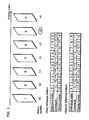
- FiG. 3 is a diagram for explaining the method for assigning two reference indices to picture numbers. Supposing that there is a sequence of pictures ordered in display order as shown in this diagram, picture numbers are assigned to the pictures in coding order. Commands for assigning reference indices to picture numbers are described in a header of each slice that is a subdivision of a picture, as the unit of coding, and thus the assignment thereof is updated every time one slice is coded. The command indicates, in series by the number of reference indices, the differential value between a picture number which is assigned a reference index currently and a picture number which is assigned a reference index immediately before the current assignment.
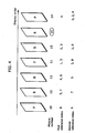
- FIG. 4 shows the result of assignment of the reference indices. This diagram shows that the first reference index and the second reference index are assigned to each picture number separately, but a plurality of reference indices are assigned to one picture number in some cases. In the coding method of the present invention, it is assumed that a plurality of reference indices are assigned to at least one picture number, like this example.
- the predictive image generation method in the motion compensation coding unit 107 as shown in FIG. 1 will be explained using FIG. 5 .
- the predictive image generation method by linear prediction is exactly the same as the conventional method, flexibility in selection of linear prediction coefficients is increased because a plurality of reference index numbers can be corresponded to the same picture.
- FIG. 7 shows an example of tables of the weighting coefficient sets included in the slice header area.
- Each data indicated by an identifier pset has four values w1, w2, c and d, and these tables are structured so that the data can be directly referred to by the values of ref1 and ref2.
- command sequences idx_cmd1 and idx_cmd2 for assigning the reference indices to the picture numbers are described in the slice header area.
- This linear prediction method has a dramatic effect particularly in the case where the brightness of the entire picture or a part thereof changes significantly like fade and flash. In many cases, the degree of change in brightness differs from part to part of a picture. Therefore, the structure of the present invention in which the best one can be selected for each block from among a plurality of weighting coefficient sets is very effective in image coding.
- FIG. 8 is a functional block diagram showing the functional structure for generating a predictive image in the linear prediction coefficient generation unit 110, the linear prediction coefficient storage unit 109 and the motion compensation coding unit 107.
- the weighting coefficient sets generated by the linear prediction coefficient generation unit 110 are stored in the linear prediction coefficient storage unit 109a and the linear coefficient storage unit 109b.
- the average calculation unit 107a obtains, from the linear prediction coefficient storage unit 109a, one set of weighting coefficients (w1_1, w2_1, c_1, d_1) selected by the first reference index ref1 determined by the motion estimation processing, and further obtains, from the linear coefficient storage unit 109b, one set of weighting coefficients (w1_2, w2_2, c_2, d_2) selected by the second reference index ref2.
- the average calculation unit 107a calculates the average, for respective parameters, of the weighting coefficient sets obtained from the linear prediction coefficient storage units 109a and 109b so as to consider it as the weighting coefficient set (w1, w2, c, d) to be used for the actual linear prediction, and outputs it to the linear prediction operation unit 107b.
- the linear prediction operation unit 107b calculates the predictive image using the equation 1 based on the obtained weighting coefficient set (w1, w2, c, d) for output.
- the weighting coefficient sets generated by the linear prediction coefficient generation unit 110 are stored in the linear prediction coefficient storage unit 109c and the linear prediction coefficient storage unit 109d.
- the average calculation unit 107f obtains, from the linear prediction coefficient storage unit 109c, the parameters of c_1 and d_1 in one set of weighting coefficients (w1_1, w2_1, c_1, d_1) selected by the first reference index ref1 determined by the motion estimation processing, and similarly, obtains, from the linear prediction coefficient storage unit 109d, the parameters of c_2 and d_2 in one set of weighting coefficients (w1_2, w2_2, c_2, d_2) selected by the second reference index ref2.
- the average calculation unit 107f calculates the average of c_1 and c_2 and the average of d_1 and d_2 obtained from the linear prediction coefficient storage unit 109c and the linear prediction coefficient storage unit 109d so as to obtain c and d for output to the linear prediction operation unit 107g.
- the linear prediction operation unit 107g uses the following rule.
- the linear prediction coefficient storage unit 109d does not need w1_2 in the weighting coefficient set. Therefore, w1 is not required for the weighting coefficient set for ref2, and thus data amount of a coded stream can be reduced.
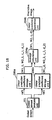
- FIG. 10B is a functional block diagram showing another functional structure for generating a predictive image.
- a predictive image is generated via the linear prediction coefficient generation unit 110, the linear prediction coefficient storage unit 109e, the linear prediction coefficient storage unit 109f and the linear prediction operation unit 107h.
- the weighting coefficient sets generated by the linear prediction coefficient generation unit 110 are stored in the linear prediction coefficient storage unit 109e and the linear prediction coefficient storage unit 109f.
- the linear prediction operation unit 107h obtains, from the linear prediction coefficient storage unit 109e, the parameters of w1_1, c_1 and d_1 which are a part of one set of weighting coefficients (w1_1, w2_1, c_1, d_1) selected by the first reference index ref1 determined by the motion estimation processing, and similarly, obtains, from the linear prediction coefficient storage unit 109f, the parameter of w2_2 which is a part of one set of weighting coefficients (w1_2, w2_2, c_2, d_2) selected based on the second reference index ref2.
- the linear prediction operation unit 107h calculates a predictive image using the equation 1 based on w1_1, c_1, d_1, w2_2 obtained from the linear prediction coefficient storage unit 109e and the linear prediction coefficient storage unit 109f for output
- Equation 4 a linear prediction equation, instead of the equation 3.
- Q1(i) is a pixel value of a block which is referred to
- P(i) is a pixel value of a predictive image of a current block to be coded
- w1, c and d are linear prediction coefficients given by the selected weighting coefficient set.
- P i w ⁇ 1 ⁇ Q ⁇ 1 i / pow 2 , d + c (where pow(2, d) indicates the "d"th power of 2)
- the pictures which are referred to in motion compensation are determined by designating the reference indices assigned to respective pictures. In that case, the maximum number of pictures which are available for reference has been described in the picture common information area in the coded stream.
- Information required for coding is not the maximum number of real pictures themselves, but the maximum reference index value available for designating pictures.
- the maximum number of reference indices is described in the picture common information, but it may be structured so that the maximum number of reference indices is described in the slice data area as well as in the picture common information.
- the maximum number of reference indices required for each slice can be clearly described, in the case where the maximum number of required reference indices for each slice is significantly different from the maximum number thereof described in the picture common information area, from slice to slice, for example, the maximum number of reference indices in a picture is 8, the maximum number of reference indices required for the slice 1 in the picture is 8, and the maximum number of reference indices required for the slice 2 is 4.
- FIG. 23 and FIG. 38 show the examples where a coded stream is made up of a picture common information area and slice data areas, the picture common information area and the slice data areas can be handled as separate coded streams in exactly the same manner as one coded stream.
- the moving picture coding method in the second embodiment of the present invention will be explained. Since the structure of the coding apparatus, the flow of coding processing and the reference index assignment method are exactly the same as those in the first embodiment, the explanation thereof is not repeated here.
- linear prediction is performed on each pixel for generating a predictive image in motion compensation using the equation 1, the equation 3 or the equation 4.
- equation 1 the equation 3 or the equation 4.
- Equation 5 is pixel values of referred blocks
- P(i) is a pixel value of a predictive image of a current block to be coded
- m, n and c are linear prediction coefficients given by a selected weighting coefficient set.
- the equation 5 is used for generating a predictive image with reference to two pictures at a time
- the equation 6 or the equation 7 is used for generating a predictive image with reference to only one picture. Since these equations require identifiers indicating plus and minus signs, weighting coefficient sets required for prediction operations are (sign1, m, sign2, n, c) for the equations 5 and 6, and (sign1, m, c) for the equation 7.
- "sing1" and "sign2" are parameters identifying the first and second plus and minus signs, respectively. Although the number of parameters is larger than that in the first embodiment, there is little increase in processing amount because both sign1 and sign2 can be represented by 1 bit.
- the linear prediction operation unit 107c calculates a predictive image 1 based on the weighting coefficient set (sign1_1, m_1, sign2_1, n_1, c_1) obtained from the linear prediction coefficient storage unit 109a.
- the linear prediction operation unit 107d calculates a predictive image 2 based on the weighting coefficient set (sign1_2, m_2, sign2_2, n_2, c_2) obtained from the linear prediction coefficient storage unit 109b.
- the average calculation unit 107e calculates, for respective pixels, the average of the predictive images calculated by the linear prediction operation units 107c and 107d so as to obtain a predictive image.
- the linear prediction operation unit 107c first calculates the predictive image using the equation 5 based on the weighting coefficient set (sign1_1, m_1, sign2_1, n_1, c_1), so it is possible to calculate the predictive image using bit shift operations without using multiplications. The same goes for the linear prediction operation unit 107d.
- the linear prediction operation unit 107d On the other hand, in the case of FIG.
- the linear prediction operation unit 107g calculates a predictive image using the equation 5, based on the parameters sign1_1 and m_1 which are obtained from the linear prediction coefficient storage unit 109c and used for bit shift operations; the parameters sign2_2 and n_2 which are obtained from the linear prediction coefficient storage unit 109d and used for bit shift operations; and the average c calculated by the average calculation unit 107f, of the parameters c_1 and c_2 which are obtained from the linear prediction coefficient storage units 109c and 109d.
- the coefficients used for bit shift operations are the values which are obtained directly from the linear prediction coefficient storage unit 109c or the linear prediction coefficient storage unit 109d, the exponents of 2 in the equation 5 are integers. Therefore, the calculations can be performed using bit shift operations, and thus the processing amount can be reduced.
- the linear prediction coefficient generation unit 110 in FIG. 1 selects, as one of the choices, only the values available for bit shift operations and describes the selected values directly into the coded streams in FIG. 6 and FIG. 12 , as the values of w1 and w2 therein.
- the linear prediction coefficient generation unit 110 in FIG. 1 selects, as one of the choices, only the values available for bit shift operations and describes the selected values directly into the coded streams in FIG. 6 and FIG. 12 , as the values of w1 and w2 therein.
- the values of w1 and w2 so that 1 is always selected for such values and generate the optimum values of only c1 and c2, which are DC components, in the linear prediction coefficient generation unit 110.
- (1, c_1) for ref1 and (1, c_2) for ref2 are coded as parameter sets.
- the pixel value P(i) of the predictive image is calculated by the following equation in which w1_1 and w2_2 in the equation 1a are substituted for 1.
- P i Q ⁇ 1 i + Q ⁇ 2 i / pow 2 ⁇ d + c_ 1 + c_ 2 / 2 (where pow(2, d) indicates the "d"th power of 2)
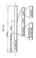
- FIG. 24 shows an example where a flag sft_flg, indicating whether or not it is possible to perform linear prediction using only bit shift operations, and a flag dc_flg, indicating whether or not it is possible to perform linear prediction using only c that is a DC component, are described in picture common information in a coded stream of a picture.
- a decoding apparatus can decode the picture without reference to these flags.
- these flags it is possible to perform decoding in the structure suitable for linear prediction using only bit shift operations or decoding in the structure suitable for linear prediction using only a DC component, so these flags could be very important information depending on the structure of the decoding apparatus.
- FIG. 24 shows the example where a coded stream is made up of a picture common information area and slice data areas
- the picture common information area and the slice data areas can be handled as separate coded streams in exactly the same manner as one coded stream.
- sft_flg and dc_flg are described in the picture common information area, but they can be handled in exactly the same manner even if they are described in the sequence common information area or another independent common information area.
- the moving picture coding method in the third embodiment of the present invention will be explained. Since the structure of the coding apparatus, the flow of coding processing and the reference index assignment method are exactly same as those in the first embodiment, the explanation thereof is not repeated here.
- the equations 8a and 8b are used instead of the equations 2a and 2b. These equations 8a and 8b are obtained by adding C1 and C2 to the equations 2a and 2b. Since only the number of additions increases for the operation, there is little increase in processing amount, compared with the original equations 2a and 2b.
- Q1(i) and Q2(i) are pixel values of referred blocks
- P(i) is a pixel value of a predictive image of a current block to be coded
- C1 and C2 are linear prediction coefficients given by a selected weighting coefficient set.
- P i 2 ⁇ Q ⁇ 1 i + C ⁇ 1 - Q ⁇ 2 i + C ⁇ 2
- P i Q ⁇ 1 i + C ⁇ 1 + Q ⁇ 2 i + C ⁇ 2 / 2
- the equations 8a and 8b are prediction equations for generating a predictive image with reference to two pictures at a time, but when generating a predictive image with reference to only one picture, the equation 9 is used instead of the equation 3 or 4 as explained in the above embodiments.
- P i Q ⁇ 1 i + C ⁇ 1
- the weighting coefficient sets for using this method are only (C1) for ref1 and (C2) for ref2. Therefore, an example of a coded stream of a picture obtained using this method is as shown in FIG. 14 .
- the weighting coefficient sets for linear prediction (pset0, pset1, pset2, «) are described for ref1 and ref2 separately, and each of the weighting coefficient sets includes only C.
- FIG. 15 shows an example of weighting coefficient sets included in the slice header area. Differently from FIG. 7 , each of the weighting coefficient sets in FIG. 15 includes only C.
- FIG. 16 is a block diagram showing the functional structure for generating a predictive image via the linear prediction coefficient generation unit 110, the linear prediction coefficient storage unit 109 and the motion compensation coding unit 107 in FIG. 1 .
- a predictive image is generated via the linear prediction coefficient generation unit 110, the linear prediction coefficient storage unit 109g, the linear prediction coefficient storage unit 109h and the linear prediction operation unit 107i.
- the weighting coefficient sets generated by the linear prediction coefficient generation unit 110 are stored in the linear prediction coefficient storage unit 109g and the linear prediction coefficient storage unit 109h.
- the weighting coefficient sets (C1) and (C2) having one element respectively are obtained from the linear prediction coefficient storage units 109g and 109h. These values are inputted to the linear prediction operation unit 107i, where linear prediction is performed on them using the equations 8a and 8b, and then the predictive image is generated.
- the linear prediction coefficient generation unit 110 generates the weighting coefficient sets (C1) and (C2) by examining the characteristics of a picture, creates a predictive image using the method as explained in FIG. 16 , and then determines a combination of the two reference indices ref1 and ref2 so as to minimize the prediction error.
- the coding apparatus can determine the values of parameters easily and further the data amount to be described in the coded stream can be reduced. Also, since the linear prediction equations do not require complicated operations such as multiplications, the operation amount can also be minimized. In addition, the use of the coefficients C1 and C2 allows dramatic improvement of the low prediction accuracy, which is considered as a disadvantage of the conventional method of using a fixed equation.
- the moving picture coding method in the fourth embodiment of the present invention will be explained. Since the structure of the coding apparatus, the flow of coding processing and the reference index assignment method are exactly same as those in the first embodiment, the explanation thereof is not repeated here.
- Display order information indicating display time or the alternative thereto as well as a picture number are assigned to each picture.
- FIG. 39 is a diagram showing an example of picture numbers and the corresponding display order information. Certain values are assigned to the display order information according to display order. In this example, the value which increases one by one for each picture is used. A method for generating values of coefficients used in an equation for linear prediction using this display order information will be explained in the fourth embodiment.
- linear prediction is performed for each pixel using the equation 1, the equation 3 or the equation 4 when generating a predictive image in motion compensation.
- the linear prediction requires data of coefficients, such coefficient data is described in slice header areas in a coded stream as weighting coefficient sets to be used for creation of the predictive image.
- this method achieves high coding efficiency, it requires additional processing for creating data of the weighting coefficient sets and causes increase in bit amount because the weighting coefficient sets are described in the coded stream.
- the weighting coefficients can be determined based on only the display order information of each reference picture, so there is no need to code the weighting coefficient sets separately.
- Q1(i) and Q2(i) are pixel values of referred blocks
- P(i) is a pixel value of a predictive image of a current block to be coded
- V0 and V1 are weighting coefficients
- T0 is the display order information of the current picture to be coded
- T1 is the display order information of the picture designated by the first reference index
- T2 is the display order information of the picture designated by the second reference index.
- V i V ⁇ 1 ⁇ Q ⁇ 1 i + V ⁇ 2 ⁇ Q ⁇ 2 i
- V ⁇ 1 T ⁇ 2 - T ⁇ 0 / T ⁇ 2 - T ⁇ 1
- V ⁇ 2 T ⁇ 0 - T ⁇ 1 / T ⁇ 2 - T ⁇ 1
- the display order information of respective pictures are 15, 13 and 10, and thus the following linear prediction equations are determined.
- the above equations Compared with the method for performing linear prediction using the weighting coefficient sets in the equation 1, the above equations have lower flexibility of coefficient values, and thus it can be said that it is impossible to create the optimum predictive image. However, compared with the method of switching the two fixed equations 2a and 2b depending on the positional relationship between two reference pictures, the above equations are more efficient linear prediction equations.
- equations 11a and 12a do not hold because T1 becomes equal to T2 when the first reference index and the second reference index refer to different pictures but these pictures have the same display order information.
- linear prediction shall be performed using 1/2 as the values of V1 and V2.
- Such predetermined coefficient may be one having the same weight like 1/2 as shown in the above example.
- V ⁇ 2 ⁇ pow 2
- v ⁇ 2 apx ⁇ T ⁇ 0 - T ⁇ 1 / T ⁇ 2 - T ⁇ 1 (where pow(2, v1) indicates the "v1"th power of 2 and pow(2, v2) indicates the "v2"th power of 2)
- apx() indicates that the value in () shall be approximated to the left-hand value)
- V ⁇ 1 1 - V ⁇ 2
- V ⁇ 2 ⁇ pow 2
- v ⁇ 2 apx ⁇ T ⁇ 0 - T ⁇ 1 / T ⁇ 2 - T ⁇ 1 (where pow(2, v2) indicates the "v2"th power of 2)
- apx() indicates that the value in () shall be approximated to the left-hand value
- the value of V1 and V2 approximated to the power of 2 shall be, taking the equation 11b as an example, the value of ⁇ pow(2, v1) obtained when the values of ⁇ pow(2, v1) and (T2-T0)/(T2-T1) are mostly approximated to each other as the value of v1 changes one by one.
- V1 2 is obtained as a result of approximation.
- round-up approximation is performed on both V1 and V2 when T1 is later than T2
- round-down approximation is performed on both V1 and V2 when T1 is earlier than T2. It is also possible, in a reverse manner, to perform round-down approximation on both V1 and V2 when T1 is later than T2, and round-up approximation on both V1 and V2 when T1 is earlier than T2.
- V1 2 is obtained.
- the equation 10 is only one equation for liner prediction in the above embodiments, it is also possible to combine this method with the linear prediction method by use of the two fixed equations 2a and 2b as explained in the background art. In that case, the equation 10 is used instead of the equation 2a, and the equation 2b is used as it is. In other words, the equation 10 is used when the picture designated by the first reference index appears behind the picture designated by the second reference index in display order, whereas the equation 2b is used in other cases.
- equation 10 instead of the equation 2b and use the equation 2a as it is.
- the equation 2a is used when the picture designated by the first reference index appears behind the picture designated by the second reference index, and the equation 10 is used in other cases.
- linear prediction is performed using 1/2 as the values of V1 and V2.
- the processing for generating coefficients C is needed, and further the coefficients C needs to be coded into the slice header area, but use of C1 and C2 allows more accurate linear prediction even if the accuracy of V1 and V2 is low. This is effective particularly in the case where V1 and V2 are approximated to the powers of 2 for performing linear prediction.
- the linear prediction can be performed in the same manner in both cases where one reference index is assigned to one picture and a plurality of reference indices are assigned to one picture.
- the display order information in the present embodiment is not limited to display order, but may be the actual display time, or the order of respective pictures starting from a predetermined picture, with its value increasing as the lapse of display time.
- the moving picture coding method in the fifth embodiment of the present invention will be explained. Since the structure of the coding apparatus, the flow of coding processing and the reference index assignment method are exactly same as those in the first embodiment, the explanation thereof is not repeated here.
- FIG. 17A shows the structure used for the case where five flags (p_flag, c_flag, d_flag, t_flag, s_flag) for controlling the above switching are described in the slice header area in the coded stream.
- p_flag is a flag indicating whether weighting coefficients have been coded or not.
- c_flag is a flag indicating whether only the data of the parameter C (C1 and C2), out of the parameters for ref1 and ref2, has been coded or not.
- t_flag is a flag indicating whether weighting coefficients for linear prediction are to be generated or not using the display order information of the reference pictures.
- s_flag is a flag indicating whether the weighting coefficients for linear prediction are to be approximated to the powers of 2 or not for the calculation by use of shift operations.
- d_flag is a flag indicating whether or not to switch two predetermined fixed equations like the equations 2a and 2b depending on the temporal positional relationship between the picture designated by ref1 and the picture designated by ref2, when linear prediction is performed using such two fixed equations.
- this flag indicates the switching of the equations
- the equation 2a is used in the case where the picture designated by ref1 is later than the picture designated by ref2 in display order
- the equation 2b is used in other cases for performing linear prediction, as is the case with the conventional method.
- this flag indicates no switching of the equations, the equation 2b is always used for performing linear prediction, regardless of the positional relationship between the picture designated by ref1 and the picture designated by ref2.
- the motion compensation coding unit 107 determines whether or not to code the data concerning the weighting coefficient sets on a per-slice basis, outputs the information of the flag p_flag to the coded stream generation unit 103 based on the determination, and describes the information in the coded stream as shown in FIG. 17A .
- the weighting coefficient sets it is possible to use the weighting coefficient sets in a higher performance apparatus for performing linear prediction, and not to use the weighting coefficient sets in a lower performance apparatus for performing linear prediction.
- the motion compensation coding unit 107 determines, on a per-slice basis, whether or not to code only the data concerning the parameter C (C1 and C2) corresponding to the DC components of image data, outputs the information of the flag c_flag to the coded stream generation unit 103 based on the determination, and describes the information in the coded stream as shown in FIG. 17A .
- the motion compensation coding unit 107 determines, on a per-slice basis, whether or not to code only the data concerning the parameter C (C1 and C2) corresponding to the DC components of image data, outputs the information of the flag c_flag to the coded stream generation unit 103 based on the determination, and describes the information in the coded stream as shown in FIG. 17A .
- the motion compensation coding unit 107 determines, on a per-slice basis, whether or not to perform coding by switching two equations, outputs the information of the flag d_flag to the coded stream generation unit 103 based on the determination, and describes the information in the coded stream as shown in FIG. 17A .
- the fixed equations for linear prediction in the case where there is little temporal change in brightness of a picture, and to switch between the two fixed equations for linear prediction in the case where the brightness of the picture changes as time goes by.
- the motion compensation coding unit 107 determines, on a per-slice basis, whether or not to generate coefficients for linear prediction using the display order information of the reference pictures, outputs the information of the flag t_flag to the coded stream generation unit 103 based on the determination, and describes the information in the coded stream as shown in FIG. 17A .
- the motion compensation coding unit 107 determines, on a per-slice basis, whether or not to approximate the coefficients for linear prediction to the powers of 2 so as to allow the calculation of these coefficients by shift operations, outputs the information of the flag s_flag to the coded stream generation unit 103 based on the determination, and describes the information in the coded stream as shown in FIG. 17A .
- the determinations are made using five flags (p_flag, c_flag, d_flag, t_flag, s_flag), each of which is 1 bit, but it is also possible to represent the determinations with only one flag of 5 bits, instead of these five flags. In that case, coding by use of variable length coding is available, not by representation with 5 bits.
- the conventional method allows switching, on a picture-by-picture basis, between the predictive image generation method by use of fixed equations and the predictive image generation method by use of weighting coefficient sets of linear prediction coefficients, by providing a flag for switching these methods in a picture common information area in a coded stream.
- the predictive image generation method can only be switched on a picture-by-picture basis.
- the present embodiment allows switching of the predictive image generation method in each slice being a subdivision of a picture by providing this switching flag in a slice header in a coded stream. Therefore, it is possible to generate a predictive image using the weighting coefficients in a slice having complex images and to generate a predictive image using fixed equations in a slice having simple images, and thus it is possible to improve the image quality while minimizing the increase in processing amount.
- the display order information in the present embodiment is not limited to display order, but may be the actual display time, or the order of respective pictures starting from a predetermined picture, with its value increasing as the lapse of display time.
- Fig. 2 is a block diagram showing a structure of a moving picture decoding apparatus in the sixth embodiment of the present invention.
- the moving picture decoding method executed by this moving picture decoding apparatus will be explained in the following order: (1) an overview of decoding and (2) a method for assigning reference indices, and (3) a method for generating a predictive image.
- a coded stream which is generated by the moving picture coding method in the first embodiment is inputted to the present decoding apparatus.
- the coded stream analysis unit 201 extracts the data sequence of weighting coefficient sets for linear prediction and the command sequence for assignment of reference indices from the slice header area, and various information such as the reference index information, the motion vector information and the coded prediction error data from the coded block information area.
- FIG. 6 shows the above-mentioned various coded information in the coded stream.
- the data sequence of the weighting coefficient sets for linear prediction extracted by the coded stream analysis unit 201 is outputted to a linear prediction coefficient storage unit 206, the command sequence for reference index assignment is outputted to a reference index/picture number conversion unit 207, the reference indices are outputted to a motion compensation decoding unit 204, the motion vector information is outputted to a motion vector storage unit 205, and the coded prediction error signal is outputted to a prediction error decoding unit 202, respectively.
- the prediction error decoding unit 202 performs image decoding processing such as inverse-quantization and inverse-frequency transform for the inputted coded prediction error signal, and outputs a decoded error signal.
- the addition unit 208 adds the decoded prediction error signal and the predictive image signal outputted from the motion compensation decoding unit 204 to generate a reconstructed image signal.
- the obtained reconstructed image signal is stored into a picture memory 203 for use for reference in the following inter-picture prediction and output for display.
- the motion compensation decoding unit 204 extracts an image area which is most suitable as a predictive image from the reconstructed image signals stored in the picture memory 203, using the motion vectors inputted from the motion vector storage unit 205 and the reference indices inputted from the coded stream analysis unit 201.
- the reference index/picture number conversion unit 207 designates the reference pictures in the picture memory 203 based on the correspondence between the reference indices given from the coded stream analysis unit 201 and the picture numbers.
- the motion compensation decoding unit 204 performs pixel value conversion processing such as interpolation processing by linear prediction on pixel values in the extracted image area, so as to generate the final predictive image.
- the linear prediction coefficients used for that processing are obtained from the data stored in the linear prediction coefficient storage unit 206 using the reference indices as search keys.
- the decoded image generated through the above-mentioned series of processes is stored in the picture memory 203, and outputted as a picture signal for display according to display timing.
- a switch 209 switches between inter-picture prediction decoding and intra-picture prediction decoding.
- a predictive image is not generated by motion compensation, but a decoded image is generated by generating a predictive image of a current area to be decoded from a decoded area in the same picture and adding the predictive image.
- the decoded image is stored in the picture memory 203, as is the case with the inter-picture prediction decoding, and outputted as a picture signal for display according to display timing.
- FIG. 3 is a diagram for explaining a method for assigning two reference indices to picture numbers.
- picture numbers are assigned in decoding order.
- Commands for assigning the reference indices to the picture numbers are described in a header of a slice that is a subdivision of a picture, as the unit of decoding, and thus the assignment thereof is updated every time one slice is decoded.
- the command indicates, in series by the number of reference indices, the differential value between a picture number which is assigned a reference index currently and a picture number which is assigned a reference index immediately before the current assignment.
- the conventional method of one-to-one assignment of reference indices to picture numbers is the most efficient method.
- the same linear prediction coefficients have to be used for all the blocks having the same reference pictures, so there is an extremely high possibility that the optimum predictive image cannot be generated.
- the above description shows the case where the picture numbers are given assuming that all the reference pictures are stored in a reference memory.
- a current picture is given a picture number which is larger by one than the number of a picture which has been coded immediately before the current picture, only when the current picture which has been coded lastly is stored, so the continuity of the picture numbers are maintained in the reference memory even if some pictures are not stored, and thus the above-mentioned method can be used without change.
- FIG. 7 shows an example of tables of the weighting coefficient sets included in the slice header area.
- Each data indicated by an identifier pset has four values w1, w2, c and d, and these tables are structured so that these values can be directly referred to by the values of ref1 and ref2.
- command sequences idx_cmd1 and idx_cmd2 for assigning the reference indices to the picture numbers are described in the slice header area.
- the average calculation unit 204a obtains, from the linear prediction coefficient storage unit 206a, one set of weighting coefficients (w1_1, w2_1, c_1, d_1) selected by ref1 outputted from the coded stream analysis unit 201, and obtains, from the linear prediction coefficient storage unit 206b, one set of weighting coefficients (w1_2, w2_2, c_2, d_2) selected by ref2 outputted from the coded stream analysis unit 201.
- the average calculation unit 204a calculates the average, for respective parameters, of the weighting coefficient sets obtained from the linear prediction coefficient storage units 206a and 206b respectively so as to output the averages to the linear prediction operation unit 204b as the weighting coefficient set (w1, w2, c, d) which is actually used for linear prediction.
- the linear prediction operation unit 204b calculates the predictive image using the equation 1 based on the weighting coefficient set (w1, w2, c, d) for output.
- FIG. 19 is a functional block diagram showing another functional structure for generating a predictive image.
- a predictive image is generated via the linear prediction coefficient storage unit 206a, the linear prediction coefficient storage unit 206b, the linear prediction operation unit 204c, the linear prediction operation unit 204d and the average calculation unit 204e.
- the average calculation unit 204e calculates the average, for respective pixel values, of the predictive images which are outputted from the linear prediction operation unit 204c and the linear prediction operation unit 204d respectively so as to generate the final predictive image for output.
- the average calculation unit 204f obtains, from the linear prediction coefficient storage unit 206c, the parameters of c_1 and d_1 in one set of weighting coefficients (w1_1, w2_1, c_1, d_1) selected by ref1 outputted from the coded stream analysis unit 201, and similarly, obtains, from the linear prediction coefficient storage unit 206d, the parameters of c_2 and d_2 in one set of weighting coefficients (w2_2, w2_2, c_2, d_2) selected by ref2 outputted from the coded stream analysis unit 201.
- the linear prediction operation unit 204g obtains the parameter of w1_1 in the above-mentioned weighting coefficient set (w1_1, w2_1, c_1, d_1) from the linear prediction coefficient storage unit 206c, obtains the parameter of w2_2 in the above-mentioned weighting coefficient set (w1_2, w2_2, c_2, d_2) from the linear prediction coefficient storage unit 206d, and obtains c and d which are the averages calculated by the average calculation unit 204f, and then calculates the predictive image using the equation 1 for output.
- the linear prediction operation unit 204h obtains, from the linear prediction coefficient storage unit 206e, the parameters of w1_1, c_1 and d_1 which are a part of one set of weighting coefficients (w1_1, w2_1, c_1, d_1) selected by ref1 outputted from the coded stream analysis unit 201, and similarly, obtains, from the linear prediction coefficient storage unit 206f, the parameter of w2_2 which is a part of one set of weighting coefficients (w1_2, w2_2, c_2, d_2) selected by ref2 outputted from the coded stream analysis unit 201.
- the linear prediction operation unit 204h calculates the predictive image using the equation 1 based on w1_1, c_1, d_1, w2_2 obtained from the linear prediction coefficient storage unit 206e and the linear prediction coefficient storage unit 206f for output.
- the linear prediction operation unit 204h uses the following rule.
- Information required for decoding is not the maximum number of real pictures themselves, but the maximum reference index value available for designating pictures.
- the maximum number of available reference indices instead of the maximum number of pictures in the background art, is described in the picture common information area being a header of the picture. Or, both of the maximum number of pictures and the maximum number of reference indices are described.
- FIG. 23 and FIG. 38 show the examples where a coded stream is made up of a picture common information area and slice data areas, the picture common information area and the slice data areas can be handled as separate coded streams in exactly the same manner as one coded stream.
- the average calculation unit 204a calculates, for respective parameters, the average of the weighting coefficient sets obtained from the linear prediction coefficient storage unit 206a and the linear prediction coefficient storage unit 206b so as to consider the average as the weighting coefficient set (sign1, m, sign2, n, c).
- the linear prediction operation unit 204b calculates the predictive image using the equation 5 based on the weighting coefficient set (sign1, m, sign2, n, c) outputted from the average calculation unit 204a.
- FIG. 18 shows the weighting coefficient set (w1_1, w2_1, c_1, d_1) and the like obtained from the linear prediction coefficient storage unit 206a and the like, which are calculated in the case where the equation 1 is used as explained in the sixth embodiment, and does not show the parameters used in the case where the predictive image is obtained using the equation 5, but the parameters used in the former case can be replaced by the parameters in the latter case as they are. The same goes for the cases of FIG. 19 and FIG. 20 to be described later.
- the average of m_1 and m_2 or the average of n_1 and n_2, namely, the exponents of 2 could not be integers, and thus there is a possibility that the processing amount increases. Also, if the exponents of 2 are rounded off to integers, there is another possibility that the error increases.
- the linear prediction operation unit 204g calculates a predictive image using the equation 5, based on the parameters sign1_1 and m_1 which are obtained from the linear prediction coefficient storage unit 206c and used for bit shift operations; the parameters sign2_2 and n_2 which are obtained from the linear prediction coefficient storage unit 206d and used for bit shift operations; and the average c calculated by the average calculation unit 204f, of the parameters c_1 and c_2 which are obtained from the linear prediction coefficient storage units 206c and 206d.
- the coefficients used for bit shift operations are values which are obtained directly from the linear prediction coefficient storage unit 206e or the linear prediction coefficient storage unit 206f, the exponents of 2 in the equation 5 are integers. Therefore, the predictive image can be calculated using bit shift operations, and thus the processing amount can be reduced.
- the decoding apparatus can perform decoding, referring to these flags, in the structure suitable for linear prediction using only bit shift operations or decoding in the structure suitable for linear prediction using only a DC component. Accordingly, processing amount can be reduced significantly depending on the structure of the decoding apparatus.
- the moving picture decoding method in the eighth embodiment of the present invention will be explained. Since the structure of the decoding apparatus, the flow of decoding processing and the reference index assignment method are exactly same as those in the sixth embodiment, the explanation thereof is not repeated here.
- equations 8a and 8b instead of the equations 2a and 2b, are used in the present embodiment.
- These equations 8a and 8b are obtained by adding C1 and C2 to the equations 2a and 2b. Since only the number of additions increases for the operation, there is little increase in processing amount, compared with the original equations 2a and 2b.
- the equations 8a and 8b are prediction equations for generating a predictive image with reference to two pictures at a time, but when generating a predictive image with reference to only one picture, the equation 9 is used instead of the equation 3 or 4 as explained in the above embodiments.
- FIG. 22 is a block diagram showing the functional structure for generating a predictive image via the linear prediction coefficient storage unit 206 and the motion compensation decoding unit 204 in FIG. 2 .
- a predictive image is generated via the linear prediction coefficient storage unit 206a, the linear prediction coefficient storage unit 206b and the linear prediction operation unit 204a.
- the moving picture decoding method in the ninth embodiment of the present invention will be explained. Since the structure of the decoding apparatus, the flow of decoding processing and the reference index assignment method are exactly the same as the sixth embodiment, the explanation thereof is not repeated here.
- Display order information indicating display time or the alternative thereto as well as a picture number are assigned to each picture.
- FIG. 39 is a diagram showing an example of picture numbers and the corresponding display order information. Certain values are assigned to the display order information according to display order. In this example, the value which increases one by one for each picture is used. A method for generating values of coefficients used in an equation for linear prediction using this display order information will be explained in the ninth embodiment.
- linear prediction is performed for each pixel using the equation 1, the equation 3 or the equation 4 when generating a predictive image in motion compensation.
- the linear prediction requires data of coefficients, such coefficient data is described in slice header areas in a coded stream as weighting coefficient sets for use for creation of the predictive image.
- this method achieves high coding efficiency, it requires additional processing for creating data of the weighting coefficient sets and causes increase in bit amount because the weighting coefficient sets are described in the coded stream.
- the weighting coefficients can be determined based on only the display order information of each reference picture, so there is no need to code the weighting coefficient sets separately.
- the display order information of respective pictures are 15, 13 and 10, and thus the following linear prediction equations are determined.
- the above equations Compared with the method for performing linear prediction using weighting coefficient sets in the equation 1, the above equations have lower flexibility of coefficient values, and thus it can be said that it is impossible to create the optimum predictive image. However, compared with the method of switching the two fixed equations 2a and 2b depending on the positional relationship between two reference pictures, the above equations are more efficient linear prediction equations.
- equations 11a and 12a do not hold because T1 becomes equal to T2 when the first reference index and the second reference index refer to difference pictures but these pictures have the same display order information.
- linear prediction shall be performed using 1/2 as the values of V1 and V2.
- Such predetermined coefficient may be one having the same weight like 1/2 as shown in the above example.
- equation 10 in the present embodiment requires multiplications and divisions for linear prediction. Since the linear prediction operation using the equation 10 is the operation on all the pixels in a current block to be decoded, addition of multiplications causes significant increase in the processing amount.
- V1 and V2 approximated to the power of 2 shall be, taking the equation 11b as an example, the value of ⁇ pow(2, v1) obtained when the values of ⁇ pow(2, v1) and (T2-T0)/(T2-T1) are mostly approximated to each other as the value of v1 changes one by one.
- V1 2 is obtained as a result of approximation.
- round-up approximation is performed on both V1 and V2 when T1 is later than T2
- round-down approximation is performed on both V1 and V2 when T1 is earlier than T2. It is also possible, in a reverse manner, to perform round-down approximation on both V1 and V2 when T1 is later than T2, and round-up approximation on both V1 and V2 when T1 is earlier than T2.
- V1 2 is obtained.
- equation 10 is only one equation for liner prediction in the above embodiments, it is also possible to combine this method with the linear prediction method by use of two fixed equations 2a and 2b as explained in the background art. In that case, the equation 10 is used instead of the equation 2a, and the equation 2b is used as it is. To be more specific, the equation 10 is used when the picture designated by the first reference index appears behind the picture designated by the second reference index in display order, whereas the equation 2b is used in other cases.
- equation 10 instead of the equation 2b and use the equation 2a as it is.
- the equation 2a is used when the picture designated by the first reference index appears behind the picture designated by the second reference index, and the equation 10 is used in other cases.
- linear prediction is performed using 1/2 as the values of V1 and V2.
- the processing for generating coefficients is needed, and further the coefficient data needs to be decoded into the slice header area, but use of C1 and C2 allows more accurate linear prediction even if the accuracy of V1 and V2 is low. This is effective particularly in the case where V1 and V2 are approximated to the powers of 2 for linear prediction.
- the linear prediction can be performed in the same manner in both cases where one reference index is assigned to one picture and a plurality of reference indices are assigned to one picture.
- the display order information in the present embodiment is not limited to display order, but may be the actual display time, or the order of respective pictures starting from a predetermined picture, with its value increasing as the lapse of display time.
- the moving picture decoding method in the tenth embodiment of the present invention will be explained. Since the structure of the decoding apparatus, the flow of decoding processing and the reference index assignment method are exactly same as the sixth embodiment, the explanation thereof is not repeated here.
- FIG. 17A shows the structure used for the case where five flags (p_flag, c_flag, d_flag, t_flag, s_flag) for controlling the above switching are described in the slice header area in the coded stream.
- p_flag is a flag indicating whether weighting coefficients have been coded or not.
- c_flag is a flag indicating whether only the data of the parameter C (C1 and C2), out of the parameters for ref1 and ref2, has been coded or not.
- t_flag is a flag indicating whether weighting coefficients for linear prediction are to be generated or not using the display order information of the reference pictures.
- s_flag is a flag indicating whether the weighting coefficients for linear prediction are to be approximated to the powers of 2 or not for the calculation by use of shift operations.
- d_flag is a flag indicating whether or not to switch two predetermined fixed equations like the equations 2a and 2b depending on the temporal positional relationship between the picture designated by ref1 and the picture designated by ref2, when linear prediction is performed using such two fixed equations.
- this flag indicates the switching of the equations
- the equation 2a is used in the case where the picture designated by ref1 is later than the picture designated by ref2 in display order and the equation 2b is used in other cases for performing linear prediction, as is the case with the conventional method.
- this flag indicates no switching of the equations, the equation 2b is always used for linear prediction, regardless of the positional relationship between the picture designated by ref1 and the picture designated by ref2.
- the coded stream analysis unit 201 analyzes the value of the flag p_flag, and outputs, to the motion compensation decoding unit 204, the instruction indicating whether or not to decode the data concerning the weighting coefficient sets so as to generate a predictive image based on the result of the analysis, and then the motion compensation decoding unit 204 performs motion compensation by linear prediction.
- the motion compensation decoding unit 204 performs motion compensation by linear prediction.
- the coded stream analysis unit 201 analyzes the value of the flag c_flag, and outputs, to the motion compensation decoding unit 204, the instruction indicating whether or not to decode only the data concerning the parameter C (C1 and C2) corresponding to the DC components of image data so as to generate a predictive image by use of fixed equations, based on the result of the analysis, and then the motion compensation decoding unit 204 performs motion compensation by linear prediction.
- the motion compensation decoding unit 204 performs motion compensation by linear prediction.
- the coded stream analysis unit 201 analyzes the value of the flag d_flag and linear prediction is performed using fixed equations based on the result of the analysis
- the coded stream analysis unit 201 outputs the instruction indicating whether or not to switch two equations for decoding to the motion compensation decoding unit 204, in which motion compensation is performed.
- the method it is possible to switch the method, such that either one of the fixed equations is used for linear prediction in the case where there is little temporal change in brightness of a picture, and the two fixed equations are switched for linear prediction in the case where the brightness of the picture changes as time goes by.
- the coded stream analysis unit 201 analyzes the value of the flag t_flag and based on the result of the analysis, it outputs, to the motion compensation decoding unit 204, the instruction indicating whether or not to generate the coefficients for linear prediction using the display order information of the reference pictures, and the motion compensation decoding unit 204 performs motion compensation.
- the coding apparatus it is possible for the coding apparatus to code the weighting coefficient sets for linear prediction in the case where more coding can be done, and to generate the coefficients from the display order information for linear prediction in the case where no more coding can be done.
- the coded stream analysis unit 201 analyzes the value of the flag s_flag, and based on the result of the analysis, it outputs, to the motion compensation decoding unit 204, the instruction indicating whether or not to approximate the coefficients for linear prediction to the powers of 2 so as to allow the calculation of these coefficients by shift operations, and the motion compensation decoding unit 204 performs motion compensation.
- the motion compensation decoding unit 204 performs motion compensation.
- the determinations are made using five flags (p_flag, c_flag, d_flag, t_flag, s_flag), each of which is 1 bit, but it is also possible to represent the determinations with only one flag of 5 bits, instead of these five flags. In that case, decoding by use of variable length decoding is available, not by representation with 5 bits.
- a flag is provided in a picture common information area of a coded stream for switching between generation of a predictive image by use of fixed equations and generation of a predictive image by use of weighting coefficient sets of linear prediction coefficients, so as to allow the switching between them on a picture-by-picture basis.
- the predictive image generation method can only be switched on a picture-by-picture basis.
- the display order information in the present embodiment is not limited to display order, but may be the actual display time, or the order of respective pictures starting from a predetermined picture, with its value increasing as the lapse of display time.
- the moving picture coding method and the moving picture decoding method in the eleventh embodiment of the present invention will be explained. Since the structures of the coding apparatus and the decoding apparatus, the flows of coding processing and decoding processing, and the reference index assignment method are exactly the same as those in the first and sixth embodiments, the explanation thereof is not repeated here.
- the motion compensation coding unit 107 determines, on a slice-by-slice basis or a block-by-block basis, whether or not to code the data concerning the parameter set, and outputs, based on the determination, the information of the flag p_flag to the coded stream generation unit 103, in which that information is described into the coded stream, as shown in FIG. 40A .
- the motion compensation coding unit 107 determines, on a slice-by-slice basis or a block-by-block basis, whether or not to code only the data concerning the parameter C (C1 and C2) corresponding to the DC components of image data, and outputs, based on the determination, the information of the flag c_flag to the coded stream generation unit 103, in which the information is described into the coded stream, as shown in FIG. 40A .
- the coded stream analysis unit 201 analyzes the values of the switching flags p_flag and c_flag, and based on the analysis, outputs, to the motion compensation decoding unit 204, the instruction indicating whether to generate a predictive image by use of the downloaded parameter sets, or to generate a predictive image by use of fixed equations, for example, and the motion compensation decoding unit 204 performs motion compensation by linear prediction.
- the coding apparatus processes the parameters as explained in FIG. 8 to FIG. 10 , for example, in the above case (1). It processes the parameters as explained in FIG. 16 , for example, in the above case (2). It processes the parameters using fixed equations, for example, in the above case (3).
- the decoding apparatus processes the parameters as explained in FIG. 18 to FIG. 20 , for example, in the above case (1). It processes the parameters as explained in FIG. 22 , for example, in the above case (2). It processes the parameters using fixed equations, for example, in the above case (3).
- coding of parameters (whether or not to have the decoding apparatus receive the parameters) is switched explicitly using the flags p_flag and c_flag, but it is also possible to use a variable length coding table (VLC table) instead of the above flags.
- VLC table variable length coding table
- no switching of the equation 2 means the following. It is explained in the background art, for example, that, in order to generate a predictive image, the fixed equation 2a including fixed coefficients is selected when the picture designated by the first reference index appears behind in display order the picture designated by the second reference index, and the equation 2b including fixed coefficients is selected in other cases. On the other hands, when it is instructed, as shown in the example of FIG. 41B , not to switch the equation, it means that the fixed equation 2b including fixed coefficients is selected even when the picture designated by the first reference index appears behind in coding order the picture designated by the second reference index so as to generate a predictive image.
- the information of the flag v_flag for selecting explicitly whether to switch between the fixed equation 2a and the fixed equation 2b is outputted from the coded stream generation unit 103 and described in the coded stream as shown in FIG. 41A .
- FIG. 41B shows an example of processing by use of the flag v_flag.
- the flag v_flag is 1
- the parameters are not coded (the parameters are not downloaded on the decoding apparatus. The same goes for the following.), and the fixed equation 2 is not switched.
- the flag v_flag is 01
- the parameters are not coded, and the fixed equation 2 is switched.
- the flag v_flag is 0000
- only the parameter C is coded, and the equation 2 is not switched.
- the flag v_flag can be switched by the motion compensation coding unit 107 in the coding apparatus as shown in FIG. 1 and the motion compensation decoding unit 204 in the decoding apparatus as shown in FIG. 2 . It is also possible to use the flag d_flag indicating whether to switch the fixed equation or not, instead of the flag v_flag, in addition to the above flags p_flag and c_flag.
- the fixed equation can be switched explicitly, the variety of means for improving the image quality is increased, and thus the coding efficiency is also improved. Also, even if the decoding apparatus does not have a fixed equation, it can switch to the fixed equation explicitly, and thus generate a predictive image using the explicitly selected fixed equation.
- the placement of the flags is not limited to that as shown in FIG. 40 .
- the values of the flags are not limited to those as explained above.
- the parameters may be assigned in the manners other than those as explained above.
- all the parameters are transmitted in the above example, but all the necessary parameter sets may be transmitted, as explained in FIG. 10 and FIG. 20 , for example.
- FIGs. 25A, 25B and 25C are illustrations showing the case where the processing is performed in a computer system using a flexible disk which stores the picture coding method or the picture decoding method of the above first to eleventh embodiments.
- FIG. 25B shows a front view and a cross-sectional view of an appearance of a flexible disk, and the flexible disk itself
- FIG. 25A shows an example of a physical format of a flexible disk as a recording medium body.
- the flexible disk FD is contained in a case F, and a plurality of tracks Tr are formed concentrically on the surface of the disk in the radius direction from the periphery and each track is divided into 16 sectors Se in the angular direction. Therefore, as for the flexible disk storing the above-mentioned program, the picture coding method as the program is recorded in an area allocated for it on the flexible disk FD.
- FIG. 25C shows the structure for recording and reproducing the program on and from the flexible disk FD.
- the program is recorded on the flexible disk FD
- the picture coding method or the picture decoding method as a program is written in the flexible disk from the computer system Cs via a flexible disk drive.
- the picture coding method is constructed in the computer system by the program on the flexible disk
- the program is read out from the flexible disk using the flexible disk drive and transferred to the computer system.
- the above explanation is made on the assumption that a recording medium is a flexible disk, but the same processing can also be performed using an optical disk.
- the recording medium is not limited to a flexible disk and an optical disk, but any other medium such as an IC card and a ROM cassette capable of recording a program can be used.
- FIG. 26 ⁇ FIG. 29 are illustrations of devices for performing the coding processing or the decoding processing as described in the above embodiments and a system using them.
- FIG. 26 is a block diagram showing the overall configuration of a content supply system ex100 for realizing content distribution service.
- the area for providing communication service is divided into cells of desired size, and base stations ex107 to ex110 which are fixed wireless stations are placed in respective cells.
- devices such as a computer ex111, a personal digital assistant (PDA) ex112, a camera ex113, a mobile phone ex114 and a camera-equipped mobile phone ex115 are connected to the Internet ex 101 via an Internet service provider ex102, a telephone network ex104 and base stations ex107 to ex110.
- PDA personal digital assistant
- the content supply system ex100 is not limited to the configuration as shown in FIG. 26 , and a combination of any of them may be connected. Also, each device may be connected directly to the telephone network ex104, not through the base stations ex107 to ex110.
- the camera ex113 is a device such as a digital video camera capable of shooting moving pictures.
- the mobile phone may be a mobile phone of a personal digital communications (PDC) system, a code division multiple access (CDMA) system, a wideband-code division multiple access (W-CDMA) system or a global system for mobile communications (GSM) system, a personal handyphone system (PHS), or the like.
- PDC personal digital communications
- CDMA code division multiple access
- W-CDMA wideband-code division multiple access
- GSM global system for mobile communications
- PHS personal handyphone system
- a streaming server ex103 is connected to the camera ex113 via the base station ex109 and the telephone network ex104, which allows live distribution or the like using the camera ex113 based on the coded data transmitted from a user.
- Either the camera ex113 or the server for transmitting the data may code the data.
- the moving picture data shot by a camera ex116 may be transmitted to the streaming server ex103 via the computer ex111.
- the camera ex116 is a device such as a digital camera capable of shooting still and moving pictures.
- Either the camera ex116 or the computer ex111 may code the moving picture data.
- An LSI ex117 included in the computer ex111 or the camera ex116 actually performs coding processing.
- Software for coding and decoding moving pictures may be integrated into any type of a storage medium (such as a CD-ROM, a flexible disk and a hard disk) being a recording medium which is readable by the computer ex111 or the like.
- a camera-equipped mobile phone ex115 may transmit the moving picture data. This moving picture data is the data coded by the LSI included in the mobile phone ex115.
- the storage medium ex207 includes a flash memory element, a kind of an electrically erasable and programmable read only memory (EEPROM) that is an electrically erasable and rewritable nonvolatile memory, in a plastic case such as an SD card.
- EEPROM electrically erasable and programmable read only memory
- a power supply circuit unit ex310 In the mobile phone ex115, a power supply circuit unit ex310, an operation input control unit ex304, a picture coding unit ex312, a camera interface unit ex303, a liquid crystal display (LCD) control unit ex302, a picture decoding unit ex309, a multiplex/demultiplex unit ex308, a record/reproduce unit ex307, a modem circuit unit ex306 and a voice processing unit ex305 are connected to a main control unit ex311 structured for overall controlling the display unit ex202 and the body unit including the operation keys ex204, and they are connected to each other via a synchronous bus ex313.
- a main control unit ex311 structured for overall controlling the display unit ex202 and the body unit including the operation keys ex204, and they are connected to each other via a synchronous bus ex313.
- the power supply circuit unit ex310 supplies respective units with power from a battery pack so as to activate the camera-equipped digital mobile phone ex115 for making it into a ready state.
- the text data of the e-mail inputted by operating the operation keys ex204 on the body unit is sent out to the main control unit ex311 via the operation input control unit ex304.
- the main control unit ex311 after the modem circuit unit ex306 performs spread spectrum processing of the text data and the send/receive circuit unit ex301 performs digital-to-analog conversion and frequency transform for it, the data is transmitted to the base station ex110 via the antenna ex201.
- the multiplex/demultiplex unit ex308 multiplexes the coded picture data supplied from the picture coding unit ex312 and the voice data supplied from the voice processing unit ex305 by a predetermined method, the modem circuit unit ex306 performs spread spectrum processing on the multiplexed data obtained as a result of the multiplexing, and the send/receive circuit unit ex301 performs digital-to-analog conversion and frequency transform on the data for transmitting via the antenna ex201.
- the picture decoding apparatus as shown in the above-mentioned embodiments can be implemented in the reproduction apparatus ex403 for reading off and decoding the coded bit stream recorded on a storage medium ex402 that is a recording medium such as a CD and DVD.
- the reproduced video signals are displayed on a monitor ex404.
- the picture decoding apparatus may be incorporated into the television, not in the set top box.
- a car ex412 having an antenna ex411 can receive signals from the satellite ex410, the base station ex107 or the like for reproducing moving pictures on a display device such as a car navigation system ex413.
- the present invention is suitable for a picture coding apparatus for performing inter-picture coding to generate a predictive image by generating commands indicating correspondence between picture numbers and reference indices for designating reference pictures and coefficients used for generation of predictive images, designating a reference picture to be referred to using a reference index, when performing motion compensation on a block in a current picture to be coded, and performing linear prediction using a coefficient corresponding to the reference index on a block obtained by motion estimation in the designated reference picture.
- the present invention is suitable for a picture decoding apparatus for decoding a coded signal obtained as a result of the coding by the picture coding apparatus.
Landscapes
- Engineering & Computer Science (AREA)
- Multimedia (AREA)
- Signal Processing (AREA)
- Compression Or Coding Systems Of Tv Signals (AREA)
- Compression, Expansion, Code Conversion, And Decoders (AREA)
Claims (2)
- Kodierverfahren des Kodierens eines zu kodierenden Bildes, wobei das Verfahren umfasst:Zuordnen eines ersten Referenzindex und eines zweiten Referenzindex, der sich von dem ersten Referenzindex unterscheidet, zu einem Referenzbild, auf das durch das zu kodierende Bild Bezug genommen werden soll,Erzeugen eines prädiktiven Pixelwerts des zu kodierenden Bildes durch Erzeugen (i) eines prädiktiven Pixelwerts eines ersten zu kodierenden Blocks unter Verwendung eines Pixelwerts eines ersten Referenzblocks und eines ersten Gewichtungskoeffizientensatzes entsprechend dem ersten Referenzindex und (ii) eines prädiktiven Pixelwerts eines zweiten zu kodierenden Blocks unter Verwendung eines Pixelwerts eines zweiten Referenzblocks und eines zweiten Gewichtungskoeffizientensatzes entsprechend dem zweiten Referenzindex, wenn der erste zu kodierende Block und der zweite zu kodierende Block in dem zu kodierenden Bild enthalten sind, wobei der erste Referenzblock für den ersten zu kodierenden Block durch den ersten Referenzindex identifiziert ist und der zweite Referenzblock für den zweiten zu kodierenden Block durch den zweiten Referenzindex identifiziert ist, undKodieren des kodierenden Bildes unter Verwendung des erzeugten prädiktiven Pixelwerts des zu kodierenden Bildes.
- Kodiervorrichtung, die zu kodierenden Bild kodiert, wobei die Vorrichtung umfasst:eine Zuordnungseinheit, die zum Zuordnen eines ersten Referenzindex und eines zweiten Referenzindex, der sich von dem ersten Referenzindex unterscheidet, zu einem Referenzbild ausgestaltet ist, auf das durch das zu kodierende Bild Bezug genommen werden soll,eine Erzeugungseinheit für ein prädiktives Bild, die zum Erzeugen eines prädiktiven Pixelwerts des zu kodierenden Bildes durch Erzeugen (i) eines prädiktiven Pixelwerts eines ersten zu kodierenden Blocks unter Verwendung eines Pixelwerts eines ersten Referenzblocks und eines ersten Gewichtungskoeffizientensatzes entsprechend dem ersten Referenzindex und (ii) eines prädiktiven Pixelwerts eines zweiten zu kodierenden Blocks unter Verwendung eines Pixelwerts eines zweiten Referenzblocks und eines zweiten Gewichtungskoeffizientensatzes entsprechend dem zweiten Referenzindex ausgestaltet ist, wenn der erste zu kodierende Block und der zweite zu kodierende Block in dem zu kodierenden Bild enthalten sind, wobei der erste Referenzblock für den ersten zu kodierenden Block durch den ersten Referenzindex identifiziert ist und der zweite Referenzblock für den zweiten zu kodierenden Block durch den zweiten Referenzindex identifiziert ist, undeine Kodiereinheit, die zum Kodieren des kodierenden Bildes unter Verwendung des erzeugten prädiktiven Pixelwerts des zu kodierenden Bildes ausgestaltet ist.
Priority Applications (2)
| Application Number | Priority Date | Filing Date | Title |
|---|---|---|---|
| EP14177815.9A EP2824928B1 (de) | 2002-08-08 | 2003-07-22 | Decodierungsverfahren für Bewegtbilder |
| EP14177707.8A EP2824927B1 (de) | 2002-08-08 | 2003-07-22 | Decodierungsverfahren für Bewegtbilder |
Applications Claiming Priority (7)
| Application Number | Priority Date | Filing Date | Title |
|---|---|---|---|
| JP2002232160 | 2002-08-08 | ||
| JP2002273992 | 2002-09-19 | ||
| JP2002289294 | 2002-10-01 | ||
| JP2002296726 | 2002-10-09 | ||
| JP2002370722 | 2002-12-20 | ||
| JP2003008751 | 2003-01-16 | ||
| EP03741520A EP1530374B1 (de) | 2002-08-08 | 2003-07-22 | Codierungsverfahren und decodierungsverfahren für bewegliche bilder |
Related Parent Applications (2)
| Application Number | Title | Priority Date | Filing Date |
|---|---|---|---|
| EP03741520A Division EP1530374B1 (de) | 2002-08-08 | 2003-07-22 | Codierungsverfahren und decodierungsverfahren für bewegliche bilder |
| EP03741520.5 Division | 2003-07-22 |
Related Child Applications (4)
| Application Number | Title | Priority Date | Filing Date |
|---|---|---|---|
| EP14177707.8A Division EP2824927B1 (de) | 2002-08-08 | 2003-07-22 | Decodierungsverfahren für Bewegtbilder |
| EP14177707.8A Division-Into EP2824927B1 (de) | 2002-08-08 | 2003-07-22 | Decodierungsverfahren für Bewegtbilder |
| EP14177815.9A Division EP2824928B1 (de) | 2002-08-08 | 2003-07-22 | Decodierungsverfahren für Bewegtbilder |
| EP14177815.9A Division-Into EP2824928B1 (de) | 2002-08-08 | 2003-07-22 | Decodierungsverfahren für Bewegtbilder |
Publications (3)
| Publication Number | Publication Date |
|---|---|
| EP2320659A2 EP2320659A2 (de) | 2011-05-11 |
| EP2320659A3 EP2320659A3 (de) | 2011-12-28 |
| EP2320659B1 true EP2320659B1 (de) | 2014-10-01 |
Family
ID=31721895
Family Applications (13)
| Application Number | Title | Priority Date | Filing Date |
|---|---|---|---|
| EP18155299.3A Expired - Lifetime EP3349447B1 (de) | 2002-08-08 | 2003-07-22 | Dekodierungsverfahren für bewegte bilder |
| EP14197723.1A Expired - Lifetime EP2928185B1 (de) | 2002-08-08 | 2003-07-22 | Kodierungsverfahren für bewegte Bilder und Dekodierungsverfahren |
| EP14177707.8A Expired - Lifetime EP2824927B1 (de) | 2002-08-08 | 2003-07-22 | Decodierungsverfahren für Bewegtbilder |
| EP17188120.4A Expired - Lifetime EP3288261B1 (de) | 2002-08-08 | 2003-07-22 | Dekodierungsverfahren für bewegte bilder |
| EP14177815.9A Expired - Lifetime EP2824928B1 (de) | 2002-08-08 | 2003-07-22 | Decodierungsverfahren für Bewegtbilder |
| EP10178519A Withdrawn EP2302931A3 (de) | 2002-08-08 | 2003-07-22 | Codierungsverfahren und Decodierungsverfahren für bewegliche Bilder |
| EP17188103.0A Expired - Lifetime EP3285486B1 (de) | 2002-08-08 | 2003-07-22 | Dekodierungsverfahren für bewegte bilder |
| EP14197718.1A Expired - Lifetime EP2903272B1 (de) | 2002-08-08 | 2003-07-22 | Kodierungsverfahren und Dekodierungsverfahren für bewegte Bilder |
| EP03741520A Expired - Lifetime EP1530374B1 (de) | 2002-08-08 | 2003-07-22 | Codierungsverfahren und decodierungsverfahren für bewegliche bilder |
| EP10178507.9A Expired - Lifetime EP2320659B1 (de) | 2002-08-08 | 2003-07-22 | Codierungsverfahren und Decodierungsverfahren für bewegliche Bilder |
| EP07123844A Withdrawn EP1906671A3 (de) | 2002-08-08 | 2003-07-22 | Verschlüsselungsverfahren für bewegte Bilder und Entschlüsselungsverfahren |
| EP14197727.2A Expired - Lifetime EP2903278B1 (de) | 2002-08-08 | 2003-07-22 | Kodierungsverfahren für bewegte Bilder |
| EP14197725.6A Expired - Lifetime EP2903277B1 (de) | 2002-08-08 | 2003-07-22 | Dekodierungsverfahren für bewegte Bilder |
Family Applications Before (9)
| Application Number | Title | Priority Date | Filing Date |
|---|---|---|---|
| EP18155299.3A Expired - Lifetime EP3349447B1 (de) | 2002-08-08 | 2003-07-22 | Dekodierungsverfahren für bewegte bilder |
| EP14197723.1A Expired - Lifetime EP2928185B1 (de) | 2002-08-08 | 2003-07-22 | Kodierungsverfahren für bewegte Bilder und Dekodierungsverfahren |
| EP14177707.8A Expired - Lifetime EP2824927B1 (de) | 2002-08-08 | 2003-07-22 | Decodierungsverfahren für Bewegtbilder |
| EP17188120.4A Expired - Lifetime EP3288261B1 (de) | 2002-08-08 | 2003-07-22 | Dekodierungsverfahren für bewegte bilder |
| EP14177815.9A Expired - Lifetime EP2824928B1 (de) | 2002-08-08 | 2003-07-22 | Decodierungsverfahren für Bewegtbilder |
| EP10178519A Withdrawn EP2302931A3 (de) | 2002-08-08 | 2003-07-22 | Codierungsverfahren und Decodierungsverfahren für bewegliche Bilder |
| EP17188103.0A Expired - Lifetime EP3285486B1 (de) | 2002-08-08 | 2003-07-22 | Dekodierungsverfahren für bewegte bilder |
| EP14197718.1A Expired - Lifetime EP2903272B1 (de) | 2002-08-08 | 2003-07-22 | Kodierungsverfahren und Dekodierungsverfahren für bewegte Bilder |
| EP03741520A Expired - Lifetime EP1530374B1 (de) | 2002-08-08 | 2003-07-22 | Codierungsverfahren und decodierungsverfahren für bewegliche bilder |
Family Applications After (3)
| Application Number | Title | Priority Date | Filing Date |
|---|---|---|---|
| EP07123844A Withdrawn EP1906671A3 (de) | 2002-08-08 | 2003-07-22 | Verschlüsselungsverfahren für bewegte Bilder und Entschlüsselungsverfahren |
| EP14197727.2A Expired - Lifetime EP2903278B1 (de) | 2002-08-08 | 2003-07-22 | Kodierungsverfahren für bewegte Bilder |
| EP14197725.6A Expired - Lifetime EP2903277B1 (de) | 2002-08-08 | 2003-07-22 | Dekodierungsverfahren für bewegte Bilder |
Country Status (9)
| Country | Link |
|---|---|
| US (15) | US7308145B2 (de) |
| EP (13) | EP3349447B1 (de) |
| KR (5) | KR101011561B1 (de) |
| CN (7) | CN101867823B (de) |
| DK (2) | DK2903277T3 (de) |
| ES (10) | ES2656106T3 (de) |
| HU (2) | HUE035701T2 (de) |
| PT (4) | PT2903277T (de) |
| WO (1) | WO2004015999A1 (de) |
Families Citing this family (72)
| Publication number | Priority date | Publication date | Assignee | Title |
|---|---|---|---|---|
| US7003035B2 (en) | 2002-01-25 | 2006-02-21 | Microsoft Corporation | Video coding methods and apparatuses |
| US20040001546A1 (en) | 2002-06-03 | 2004-01-01 | Alexandros Tourapis | Spatiotemporal prediction for bidirectionally predictive (B) pictures and motion vector prediction for multi-picture reference motion compensation |
| US8406301B2 (en) | 2002-07-15 | 2013-03-26 | Thomson Licensing | Adaptive weighting of reference pictures in video encoding |
| US7903742B2 (en) * | 2002-07-15 | 2011-03-08 | Thomson Licensing | Adaptive weighting of reference pictures in video decoding |
| US7154952B2 (en) * | 2002-07-19 | 2006-12-26 | Microsoft Corporation | Timestamp-independent motion vector prediction for predictive (P) and bidirectionally predictive (B) pictures |
| EP3349447B1 (de) | 2002-08-08 | 2019-11-06 | Godo Kaisha IP Bridge 1 | Dekodierungsverfahren für bewegte bilder |
| AU2003268563A1 (en) * | 2002-10-01 | 2004-04-23 | Thomson Licensing S.A. | Implicit weighting of reference pictures in a video decoder |
| KR100961313B1 (ko) | 2002-11-20 | 2010-06-04 | 파나소닉 주식회사 | 동화상 부호화 방법 및 장치 |
| JP2004179687A (ja) * | 2002-11-22 | 2004-06-24 | Toshiba Corp | 動画像符号化/復号化方法及び装置 |
| KR100997270B1 (ko) * | 2004-04-28 | 2010-11-29 | 파나소닉 주식회사 | 스트림 생성 장치, 스트림 생성 방법, 및 기록 매체 |
| US8731054B2 (en) | 2004-05-04 | 2014-05-20 | Qualcomm Incorporated | Method and apparatus for weighted prediction in predictive frames |
| US20060083298A1 (en) * | 2004-10-14 | 2006-04-20 | Nokia Corporation | Reference picture management in video coding |
| WO2006061838A2 (en) * | 2004-12-08 | 2006-06-15 | Imagine Communications Ltd. | Distributed statistical multiplexing of multi-media |
| KR100703749B1 (ko) * | 2005-01-27 | 2007-04-05 | 삼성전자주식회사 | 잔차 재 추정을 이용한 다 계층 비디오 코딩 및 디코딩방법, 이를 위한 장치 |
| TWI280803B (en) * | 2005-07-20 | 2007-05-01 | Novatek Microelectronics Corp | Method and apparatus for motion estimation |
| US8233535B2 (en) * | 2005-11-18 | 2012-07-31 | Apple Inc. | Region-based processing of predicted pixels |
| CN101455087B (zh) * | 2006-05-24 | 2011-01-12 | 松下电器产业株式会社 | 图像编码装置、图像编码方法及图像编码用集成电路 |
| US8295625B2 (en) * | 2006-09-30 | 2012-10-23 | Thomson Licensing | Method and device for encoding and decoding color enhancement layer for video |
| US8256005B2 (en) * | 2007-01-08 | 2012-08-28 | Apple Inc. | Protection of audio or video data in a playback device |
| JP2008177907A (ja) * | 2007-01-19 | 2008-07-31 | Fujitsu Ltd | 動画データ復号装置、情報機器、動画データ復号方法および動画データ復号プログラム |
| US8494049B2 (en) * | 2007-04-09 | 2013-07-23 | Cisco Technology, Inc. | Long term reference frame management with error video feedback for compressed video communication |
| US8254455B2 (en) * | 2007-06-30 | 2012-08-28 | Microsoft Corporation | Computing collocated macroblock information for direct mode macroblocks |
| AU2007237313A1 (en) * | 2007-12-03 | 2009-06-18 | Canon Kabushiki Kaisha | Improvement for error correction in distributed vdeo coding |
| US8270483B1 (en) * | 2008-01-18 | 2012-09-18 | Maxim Integrated Products, Inc. | Method and apparatus for applying accurate parameter estimation and efficient fade detection in weighted prediction for video compression |
| WO2009095962A1 (ja) | 2008-01-29 | 2009-08-06 | Panasonic Corporation | 画像符号化装置、画像符号化方法、画像符号化集積回路および画像符号化プログラム |
| KR101353304B1 (ko) * | 2008-10-24 | 2014-01-21 | 에스케이 텔레콤주식회사 | 적응적 보간 필터 계수를 이용한 영상 부호화/복호화 방법 및 장치 |
| US8189666B2 (en) * | 2009-02-02 | 2012-05-29 | Microsoft Corporation | Local picture identifier and computation of co-located information |
| US20110023548A1 (en) | 2009-07-29 | 2011-02-03 | Garner Sean M | Glass substrate comprising an edge web portion |
| WO2011037420A2 (ko) * | 2009-09-25 | 2011-03-31 | 에스케이텔레콤 주식회사 | 인접 화소를 이용한 인터 예측 방법 및 장치와 그를 이용한 영상 부호화/복호화 방법 및 장치 |
| CN103826131B (zh) * | 2010-04-08 | 2017-03-01 | 株式会社东芝 | 图像解码方法以及图像解码装置 |
| CN102823248B (zh) | 2010-04-08 | 2015-06-24 | 株式会社东芝 | 图像编码方法以及图像编码装置 |
| WO2011142277A1 (ja) | 2010-05-13 | 2011-11-17 | シャープ株式会社 | 予測画像生成装置、動画像復号装置、及び、動画像符号化装置 |
| KR101341993B1 (ko) | 2010-10-06 | 2013-12-16 | 에스케이텔레콤 주식회사 | 고정밀 필터를 이용한 영상 부호화/복호화 방법 및 장치 |
| WO2012047047A2 (ko) * | 2010-10-06 | 2012-04-12 | 에스케이텔레콤 주식회사 | 고정밀 필터를 이용한 영상 부호화/복호화 방법 및 장치 |
| CN107454419B (zh) * | 2010-12-13 | 2020-12-29 | 韩国电子通信研究院 | 基于帧间预测对视频信号进行解码的方法 |
| JP2014501091A (ja) | 2010-12-17 | 2014-01-16 | エレクトロニクス アンド テレコミュニケーションズ リサーチ インスチチュート | インター予測方法及びその装置 |
| US8914534B2 (en) * | 2011-01-05 | 2014-12-16 | Sonic Ip, Inc. | Systems and methods for adaptive bitrate streaming of media stored in matroska container files using hypertext transfer protocol |
| ES2621231T3 (es) | 2011-04-12 | 2017-07-03 | Sun Patent Trust | Método de codificación de video de movimiento, aparato de codificación de video de movimiento, método de decodificación de video de movimiento, aparato de decodificación de video de movimiento y aparato de codificación/decodificación de video de movimiento |
| ES2769378T3 (es) * | 2011-05-27 | 2020-06-25 | Sun Patent Trust | Procedimiento de codificación de imágenes y aparato de codificación de imágenes |
| US9485518B2 (en) | 2011-05-27 | 2016-11-01 | Sun Patent Trust | Decoding method and apparatus with candidate motion vectors |
| ES2971526T3 (es) | 2011-05-31 | 2024-06-05 | Sun Patent Trust | Procedimiento de descodificación de vídeo, dispositivo de descodificación de vídeo |
| PL2725791T3 (pl) | 2011-06-23 | 2024-02-26 | Sun Patent Trust | Sposób dekodowania obrazów, sposób kodowania obrazów |
| KR102062283B1 (ko) | 2011-06-24 | 2020-01-03 | 선 페이턴트 트러스트 | 화상 복호 방법, 화상 부호화 방법, 화상 복호 장치, 화상 부호화 장치 및 화상 부호화 복호 장치 |
| WO2012176464A1 (ja) | 2011-06-24 | 2012-12-27 | パナソニック株式会社 | 画像復号方法、画像符号化方法、画像復号装置、画像符号化装置及び画像符号化復号装置 |
| BR112013030347B1 (pt) | 2011-06-27 | 2022-06-28 | Sun Patent Trust | Método de decodificação de imagem, método de codificação de imagem, aparelho de decodificação de imagem, aparelho de codificação de imagem e aparelho de codificação e de decodificação de imagem |
| MY165469A (en) | 2011-06-28 | 2018-03-23 | Sun Patent Trust | Image decoding method, image coding method, image decoding apparatus, image coding apparatus, and image coding and decoding apparatus |
| MX2013010892A (es) | 2011-06-29 | 2013-12-06 | Panasonic Corp | Metodo de decodificacion de imagenes, metodo de codificacion de imagenes, aparato de decodificacion de imagenes, aparato de codificacion de imagenes y aparato de codificacion y decodificacion de imagenes. |
| KR102060619B1 (ko) | 2011-06-30 | 2019-12-30 | 선 페이턴트 트러스트 | 화상 복호 방법, 화상 부호화 방법, 화상 복호 장치, 화상 부호화 장치 및 화상 부호화 복호 장치 |
| PL2728869T3 (pl) | 2011-06-30 | 2022-02-28 | Sun Patent Trust | Sposób dekodowania obrazów |
| KR102404121B1 (ko) | 2011-07-11 | 2022-05-31 | 선 페이턴트 트러스트 | 화상 복호 방법, 화상 부호화 방법, 화상 복호 장치, 화상 부호화 장치 및 화상 부호화 복호 장치 |
| EP3487178A1 (de) | 2011-08-03 | 2019-05-22 | Sun Patent Trust | Videokodierungsverfahren, videodekodierungsverfahren, videokodierungsvorrichtung, videodekodierungsvorrichtung und videokodierungs-/dekodierungsvorrichtung |
| AU2011379258C1 (en) | 2011-10-17 | 2015-11-26 | Kabushiki Kaisha Toshiba | Encoding method and decoding method |
| JP5698644B2 (ja) * | 2011-10-18 | 2015-04-08 | 株式会社Nttドコモ | 動画像予測符号化方法、動画像予測符号化装置、動画像予測符号化プログラム、動画像予測復号方法、動画像予測復号装置及び動画像予測復号プログラム |
| MX2014003991A (es) | 2011-10-19 | 2014-05-07 | Panasonic Corp | Metodo de codificacion de imagenes, aparato de codificacion de imagenes, metodo de decodificacion de imagenes y aparato de decodificacion de imagenes. |
| CN104137549B9 (zh) * | 2012-01-18 | 2020-06-05 | 韩国电子通信研究院 | 对图像进行编码和解码的方法及设备 |
| MX342497B (es) * | 2012-06-29 | 2016-10-03 | Sony Corp | Dispositivo de codificacion y metodo de codificacion. |
| KR20150060730A (ko) * | 2012-09-26 | 2015-06-03 | 톰슨 라이센싱 | 인터-이미지 예측 방법과 디바이스 및 대응하는 인코딩 방법과 디바이스 |
| US9628790B1 (en) | 2013-01-03 | 2017-04-18 | Google Inc. | Adaptive composite intra prediction for image and video compression |
| JP6365924B2 (ja) * | 2013-05-09 | 2018-08-01 | サン パテント トラスト | 画像復号方法及び画像復号装置 |
| US9609343B1 (en) | 2013-12-20 | 2017-03-28 | Google Inc. | Video coding using compound prediction |
| US10148965B2 (en) * | 2015-03-04 | 2018-12-04 | Panasonic Intellectual Property Management Co., Ltd. | Moving image coding apparatus and moving image coding method |
| WO2018132150A1 (en) | 2017-01-13 | 2018-07-19 | Google Llc | Compound prediction for video coding |
| KR20240154105A (ko) | 2017-05-19 | 2024-10-24 | 파나소닉 인텔렉츄얼 프로퍼티 코포레이션 오브 아메리카 | 부호화 장치, 복호 장치, 부호화 방법 및 복호 방법 |
| US10880573B2 (en) | 2017-08-15 | 2020-12-29 | Google Llc | Dynamic motion vector referencing for video coding |
| US10284869B2 (en) | 2017-09-28 | 2019-05-07 | Google Llc | Constrained motion field estimation for hardware efficiency |
| US11789874B2 (en) | 2018-01-09 | 2023-10-17 | Qualcomm Incorporated | Method, apparatus, and system for storing memory encryption realm key IDs |
| EP3599693A1 (de) * | 2018-07-27 | 2020-01-29 | Fronius International GmbH | Lichtbogenerkennung |
| JP7304153B2 (ja) * | 2018-12-27 | 2023-07-06 | Kddi株式会社 | 動画像復号装置、動画像復号方法及びプログラム |
| CN110147330B (zh) * | 2019-05-23 | 2023-09-01 | 深圳市创维软件有限公司 | 一种字模数据的缓存方法、装置、设备和存储介质 |
| CN112584142B (zh) * | 2019-09-30 | 2022-09-30 | 杭州海康威视数字技术股份有限公司 | 一种编解码方法、装置及其设备 |
| JP2021061501A (ja) * | 2019-10-04 | 2021-04-15 | シャープ株式会社 | 動画像変換装置及び方法 |
| CN111343462B (zh) * | 2020-03-08 | 2021-10-22 | 苏州浪潮智能科技有限公司 | 一种图像数据压缩传输方法、装置及存储介质 |
Family Cites Families (26)
| Publication number | Priority date | Publication date | Assignee | Title |
|---|---|---|---|---|
| JPS59200592A (ja) * | 1983-04-27 | 1984-11-13 | Fuji Photo Film Co Ltd | カラ−画像の適応形圧縮方式 |
| JP2853553B2 (ja) * | 1994-02-22 | 1999-02-03 | 日本電気株式会社 | 動画像符号化方式 |
| JP3089941B2 (ja) | 1994-02-28 | 2000-09-18 | 日本ビクター株式会社 | 画像間予測符号化装置 |
| US5708473A (en) | 1994-08-30 | 1998-01-13 | Hughes Aircraft Company | Two stage video film compression method and system |
| KR0181034B1 (ko) * | 1995-03-18 | 1999-05-01 | 배순훈 | 특징점 기반 움직임 추정을 이용한 움직임 벡터 검출 방법 및 장치 |
| EP0935395A2 (de) * | 1998-02-06 | 1999-08-11 | Sony Corporation | Videokodierungsverfahren und -vorrichtung |
| CN1201589C (zh) * | 1999-04-06 | 2005-05-11 | 皇家菲利浦电子有限公司 | 运动估计方法和装置 |
| GB2381403B (en) * | 2000-05-10 | 2004-12-01 | Picturetel Corp | Video coding using multiple buffers |
| JP2001333389A (ja) * | 2000-05-17 | 2001-11-30 | Mitsubishi Electric Research Laboratories Inc | ビデオ再生システムおよびビデオ信号処理方法 |
| WO2003030556A1 (en) * | 2001-09-18 | 2003-04-10 | Matsushita Electric Industrial Co., Ltd. | Image encoding method and image decoding method |
| CA2574110A1 (en) * | 2002-01-18 | 2003-07-31 | Kabushiki Kaisha Toshiba | Video encoding method and apparatus and video decoding method and apparatus |
| JP4015934B2 (ja) * | 2002-04-18 | 2007-11-28 | 株式会社東芝 | 動画像符号化方法及び装置 |
| JP2004007379A (ja) * | 2002-04-10 | 2004-01-08 | Toshiba Corp | 動画像符号化方法及び動画像復号化方法 |
| KR100508798B1 (ko) | 2002-04-09 | 2005-08-19 | 엘지전자 주식회사 | 쌍방향 예측 블록 예측 방법 |
| ES2745059T3 (es) * | 2002-04-19 | 2020-02-27 | Panasonic Ip Corp America | Método de cálculo de vectores de movimiento |
| JP2004023458A (ja) * | 2002-06-17 | 2004-01-22 | Toshiba Corp | 動画像符号化/復号化方法及び装置 |
| CN1666532A (zh) * | 2002-07-02 | 2005-09-07 | 松下电器产业株式会社 | 图像编码方法和图像解码方法 |
| US7903742B2 (en) * | 2002-07-15 | 2011-03-08 | Thomson Licensing | Adaptive weighting of reference pictures in video decoding |
| WO2004012459A1 (ja) * | 2002-07-26 | 2004-02-05 | Matsushita Electric Industrial Co., Ltd. | 動画像符号化方法、動画像復号化方法および記録媒体 |
| EP3349447B1 (de) * | 2002-08-08 | 2019-11-06 | Godo Kaisha IP Bridge 1 | Dekodierungsverfahren für bewegte bilder |
| JP2004179687A (ja) * | 2002-11-22 | 2004-06-24 | Toshiba Corp | 動画像符号化/復号化方法及び装置 |
| BRPI0318759B1 (pt) * | 2002-11-25 | 2018-02-27 | Godo Kaisha Ip Bridge 1 | Método e aparelho de codificação de imagem móvel |
| KR20060037352A (ko) * | 2003-07-15 | 2006-05-03 | 톰슨 라이센싱 | 고속 검색 블록 매칭에 의한 움직임 추정 |
| JPWO2009041215A1 (ja) * | 2007-09-25 | 2011-01-20 | シャープ株式会社 | 動画像符号化装置及び動画像復号装置 |
| CN104704827B (zh) * | 2012-11-13 | 2019-04-12 | 英特尔公司 | 用于下一代视频的内容自适应变换译码 |
| WO2014120368A1 (en) * | 2013-01-30 | 2014-08-07 | Intel Corporation | Content adaptive entropy coding for next generation video |
-
2003
- 2003-07-22 EP EP18155299.3A patent/EP3349447B1/de not_active Expired - Lifetime
- 2003-07-22 ES ES14177815.9T patent/ES2656106T3/es not_active Expired - Lifetime
- 2003-07-22 ES ES14197725.6T patent/ES2638189T3/es not_active Expired - Lifetime
- 2003-07-22 ES ES14197727.2T patent/ES2636947T3/es not_active Expired - Lifetime
- 2003-07-22 EP EP14197723.1A patent/EP2928185B1/de not_active Expired - Lifetime
- 2003-07-22 ES ES14197718.1T patent/ES2673393T3/es not_active Expired - Lifetime
- 2003-07-22 DK DK14197725.6T patent/DK2903277T3/en active
- 2003-07-22 CN CN2010101550829A patent/CN101867823B/zh not_active Expired - Lifetime
- 2003-07-22 EP EP14177707.8A patent/EP2824927B1/de not_active Expired - Lifetime
- 2003-07-22 CN CN2010101550956A patent/CN101883279B/zh not_active Expired - Lifetime
- 2003-07-22 PT PT141977256T patent/PT2903277T/pt unknown
- 2003-07-22 EP EP17188120.4A patent/EP3288261B1/de not_active Expired - Lifetime
- 2003-07-22 EP EP14177815.9A patent/EP2824928B1/de not_active Expired - Lifetime
- 2003-07-22 ES ES17188103T patent/ES2767066T3/es not_active Expired - Lifetime
- 2003-07-22 KR KR1020107011291A patent/KR101011561B1/ko not_active Expired - Lifetime
- 2003-07-22 WO PCT/JP2003/009228 patent/WO2004015999A1/ja not_active Ceased
- 2003-07-22 EP EP10178519A patent/EP2302931A3/de not_active Withdrawn
- 2003-07-22 EP EP17188103.0A patent/EP3285486B1/de not_active Expired - Lifetime
- 2003-07-22 EP EP14197718.1A patent/EP2903272B1/de not_active Expired - Lifetime
- 2003-07-22 PT PT141977272T patent/PT2903278T/pt unknown
- 2003-07-22 EP EP03741520A patent/EP1530374B1/de not_active Expired - Lifetime
- 2003-07-22 US US10/491,153 patent/US7308145B2/en not_active Expired - Lifetime
- 2003-07-22 CN CN2010101550509A patent/CN101873491B/zh not_active Expired - Lifetime
- 2003-07-22 EP EP10178507.9A patent/EP2320659B1/de not_active Expired - Lifetime
- 2003-07-22 CN CN2010101550763A patent/CN101873492B/zh not_active Expired - Lifetime
- 2003-07-22 DK DK03741520.5T patent/DK1530374T3/da active
- 2003-07-22 CN CN038012561A patent/CN1568622B/zh not_active Expired - Lifetime
- 2003-07-22 ES ES03741520T patent/ES2401774T3/es not_active Expired - Lifetime
- 2003-07-22 KR KR1020047003839A patent/KR100969057B1/ko not_active Expired - Lifetime
- 2003-07-22 ES ES17188120T patent/ES2767954T3/es not_active Expired - Lifetime
- 2003-07-22 EP EP07123844A patent/EP1906671A3/de not_active Withdrawn
- 2003-07-22 KR KR1020107011292A patent/KR101000609B1/ko not_active Expired - Lifetime
- 2003-07-22 CN CN2010101550706A patent/CN101873501B/zh not_active Expired - Lifetime
- 2003-07-22 HU HUE14197723A patent/HUE035701T2/en unknown
- 2003-07-22 HU HUE18155299A patent/HUE047568T2/hu unknown
- 2003-07-22 KR KR1020107011290A patent/KR101000635B1/ko not_active Expired - Lifetime
- 2003-07-22 PT PT101785079T patent/PT2320659E/pt unknown
- 2003-07-22 CN CN200710104187XA patent/CN101083770B/zh not_active Expired - Lifetime
- 2003-07-22 ES ES10178507.9T patent/ES2524117T3/es not_active Expired - Lifetime
- 2003-07-22 PT PT37415205T patent/PT1530374E/pt unknown
- 2003-07-22 EP EP14197727.2A patent/EP2903278B1/de not_active Expired - Lifetime
- 2003-07-22 EP EP14197725.6A patent/EP2903277B1/de not_active Expired - Lifetime
- 2003-07-22 ES ES14177707.8T patent/ES2653437T3/es not_active Expired - Lifetime
- 2003-07-22 KR KR1020087016268A patent/KR100976017B1/ko not_active Expired - Lifetime
- 2003-07-22 ES ES14197723.1T patent/ES2650068T3/es not_active Expired - Lifetime
-
2007
- 2007-10-29 US US11/976,845 patent/US7817867B2/en not_active Expired - Lifetime
- 2007-10-29 US US11/976,842 patent/US7813568B2/en not_active Expired - Lifetime
- 2007-10-29 US US11/976,843 patent/US7492952B2/en not_active Expired - Lifetime
- 2007-10-29 US US11/976,860 patent/US7817868B2/en not_active Expired - Lifetime
-
2010
- 2010-09-09 US US12/878,350 patent/US8023753B2/en not_active Expired - Lifetime
-
2011
- 2011-08-12 US US13/208,677 patent/US8150180B2/en not_active Expired - Fee Related
-
2012
- 2012-02-08 US US13/368,708 patent/US8355588B2/en not_active Expired - Fee Related
- 2012-12-13 US US13/713,198 patent/US8606027B2/en not_active Expired - Fee Related
- 2012-12-13 US US13/713,211 patent/US9456218B2/en not_active Expired - Lifetime
-
2013
- 2013-11-01 US US14/069,859 patent/US9002124B2/en not_active Expired - Lifetime
- 2013-11-01 US US14/069,708 patent/US9113149B2/en not_active Expired - Lifetime
-
2016
- 2016-08-17 US US15/239,170 patent/US9942547B2/en not_active Expired - Lifetime
- 2016-08-17 US US15/239,207 patent/US9888239B2/en not_active Expired - Fee Related
-
2018
- 2018-02-28 US US15/907,643 patent/US10321129B2/en not_active Expired - Lifetime
Also Published As
Similar Documents
| Publication | Publication Date | Title |
|---|---|---|
| EP2320659B1 (de) | Codierungsverfahren und Decodierungsverfahren für bewegliche Bilder | |
| EP1450565B1 (de) | Verfahren zur codierung von bewegten bildern und verfahren zur decodierung von bewegten bildern | |
| EP1569459B1 (de) | Codierungsverfahren und decodierungsverfahren eines beweglichen bildes | |
| JP4485157B2 (ja) | 画像復号化方法および画像復号化装置 | |
| JP4485494B2 (ja) | 画像復号化方法および画像復号化装置 |
Legal Events
| Date | Code | Title | Description |
|---|---|---|---|
| PUAI | Public reference made under article 153(3) epc to a published international application that has entered the european phase |
Free format text: ORIGINAL CODE: 0009012 |
|
| AC | Divisional application: reference to earlier application |
Ref document number: 1530374 Country of ref document: EP Kind code of ref document: P |
|
| AK | Designated contracting states |
Kind code of ref document: A2 Designated state(s): AT BE BG CH CY CZ DE DK EE ES FI FR GB GR HU IE IT LI LU MC NL PT RO SE SI SK TR |
|
| PUAL | Search report despatched |
Free format text: ORIGINAL CODE: 0009013 |
|
| AK | Designated contracting states |
Kind code of ref document: A3 Designated state(s): AT BE BG CH CY CZ DE DK EE ES FI FR GB GR HU IE IT LI LU MC NL PT RO SE SI SK TR |
|
| RIC1 | Information provided on ipc code assigned before grant |
Ipc: H04N 7/50 20060101ALI20111123BHEP Ipc: H04N 7/46 20060101ALI20111123BHEP Ipc: H04N 7/36 20060101ALI20111123BHEP Ipc: H04N 7/26 20060101AFI20111123BHEP |
|
| 17P | Request for examination filed |
Effective date: 20120330 |
|
| REG | Reference to a national code |
Ref country code: DE Ref legal event code: R079 Ref document number: 60346841 Country of ref document: DE Free format text: PREVIOUS MAIN CLASS: H04N0007260000 Ipc: H04N0019573000 |
|
| GRAP | Despatch of communication of intention to grant a patent |
Free format text: ORIGINAL CODE: EPIDOSNIGR1 |
|
| INTG | Intention to grant announced |
Effective date: 20140508 |
|
| RIC1 | Information provided on ipc code assigned before grant |
Ipc: H04N 19/58 20140101ALI20140428BHEP Ipc: H04N 19/61 20140101ALI20140428BHEP Ipc: H04N 19/573 20140101AFI20140428BHEP Ipc: H04N 19/577 20140101ALI20140428BHEP |
|
| RAP1 | Party data changed (applicant data changed or rights of an application transferred) |
Owner name: PANASONIC INTELLECTUAL PROPERTY CORPORATION OF AME |
|
| GRAS | Grant fee paid |
Free format text: ORIGINAL CODE: EPIDOSNIGR3 |
|
| GRAA | (expected) grant |
Free format text: ORIGINAL CODE: 0009210 |
|
| AC | Divisional application: reference to earlier application |
Ref document number: 1530374 Country of ref document: EP Kind code of ref document: P |
|
| AK | Designated contracting states |
Kind code of ref document: B1 Designated state(s): AT BE BG CH CY CZ DE DK EE ES FI FR GB GR HU IE IT LI LU MC NL PT RO SE SI SK TR |
|
| REG | Reference to a national code |
Ref country code: GB Ref legal event code: FG4D |
|
| REG | Reference to a national code |
Ref country code: AT Ref legal event code: REF Ref document number: 690017 Country of ref document: AT Kind code of ref document: T Effective date: 20141015 Ref country code: CH Ref legal event code: NV Representative=s name: NOVAGRAAF INTERNATIONAL SA, CH Ref country code: CH Ref legal event code: EP |
|
| REG | Reference to a national code |
Ref country code: IE Ref legal event code: FG4D |
|
| REG | Reference to a national code |
Ref country code: PT Ref legal event code: SC4A Free format text: AVAILABILITY OF NATIONAL TRANSLATION Effective date: 20141105 Ref country code: DE Ref legal event code: R096 Ref document number: 60346841 Country of ref document: DE Effective date: 20141113 |
|
| REG | Reference to a national code |
Ref country code: ES Ref legal event code: FG2A Ref document number: 2524117 Country of ref document: ES Kind code of ref document: T3 Effective date: 20141204 |
|
| REG | Reference to a national code |
Ref country code: GR Ref legal event code: EP Ref document number: 20140402199 Country of ref document: GR Effective date: 20141121 |
|
| REG | Reference to a national code |
Ref country code: NL Ref legal event code: T3 |
|
| PG25 | Lapsed in a contracting state [announced via postgrant information from national office to epo] |
Ref country code: FI Free format text: LAPSE BECAUSE OF FAILURE TO SUBMIT A TRANSLATION OF THE DESCRIPTION OR TO PAY THE FEE WITHIN THE PRESCRIBED TIME-LIMIT Effective date: 20141001 Ref country code: CZ Free format text: LAPSE BECAUSE OF FAILURE TO SUBMIT A TRANSLATION OF THE DESCRIPTION OR TO PAY THE FEE WITHIN THE PRESCRIBED TIME-LIMIT Effective date: 20141001 |
|
| PG25 | Lapsed in a contracting state [announced via postgrant information from national office to epo] |
Ref country code: SE Free format text: LAPSE BECAUSE OF FAILURE TO SUBMIT A TRANSLATION OF THE DESCRIPTION OR TO PAY THE FEE WITHIN THE PRESCRIBED TIME-LIMIT Effective date: 20141001 Ref country code: CY Free format text: LAPSE BECAUSE OF FAILURE TO SUBMIT A TRANSLATION OF THE DESCRIPTION OR TO PAY THE FEE WITHIN THE PRESCRIBED TIME-LIMIT Effective date: 20141001 |
|
| REG | Reference to a national code |
Ref country code: FR Ref legal event code: PLFP Year of fee payment: 13 |
|
| REG | Reference to a national code |
Ref country code: DE Ref legal event code: R097 Ref document number: 60346841 Country of ref document: DE |
|
| PG25 | Lapsed in a contracting state [announced via postgrant information from national office to epo] |
Ref country code: EE Free format text: LAPSE BECAUSE OF FAILURE TO SUBMIT A TRANSLATION OF THE DESCRIPTION OR TO PAY THE FEE WITHIN THE PRESCRIBED TIME-LIMIT Effective date: 20141001 Ref country code: DK Free format text: LAPSE BECAUSE OF FAILURE TO SUBMIT A TRANSLATION OF THE DESCRIPTION OR TO PAY THE FEE WITHIN THE PRESCRIBED TIME-LIMIT Effective date: 20141001 Ref country code: SK Free format text: LAPSE BECAUSE OF FAILURE TO SUBMIT A TRANSLATION OF THE DESCRIPTION OR TO PAY THE FEE WITHIN THE PRESCRIBED TIME-LIMIT Effective date: 20141001 |
|
| PLBE | No opposition filed within time limit |
Free format text: ORIGINAL CODE: 0009261 |
|
| STAA | Information on the status of an ep patent application or granted ep patent |
Free format text: STATUS: NO OPPOSITION FILED WITHIN TIME LIMIT |
|
| 26N | No opposition filed |
Effective date: 20150702 |
|
| REG | Reference to a national code |
Ref country code: DE Ref legal event code: R082 Ref document number: 60346841 Country of ref document: DE Representative=s name: EISENFUEHR SPEISER PATENTANWAELTE RECHTSANWAEL, DE Ref country code: DE Ref legal event code: R081 Ref document number: 60346841 Country of ref document: DE Owner name: GODO KAISHA IP BRIDGE 1, JP Free format text: FORMER OWNER: PANASONIC INTELLECTUAL PROPERTY CORP. OF AMERICA, TORRANCE, CALIF., US |
|
| REG | Reference to a national code |
Ref country code: CH Ref legal event code: PUE Owner name: GODO KAISHA IP BRIDGE 1, JP Free format text: FORMER OWNER: PANASONIC INTELLECTUAL PROPERTY CORPORATION OF AMERICA, US Ref country code: CH Ref legal event code: NV Representative=s name: SCHNEIDER FELDMANN AG PATENT- UND MARKENANWAEL, CH |
|
| REG | Reference to a national code |
Ref country code: GB Ref legal event code: 732E Free format text: REGISTERED BETWEEN 20150924 AND 20150930 |
|
| REG | Reference to a national code |
Ref country code: RO Ref legal event code: EPE |
|
| REG | Reference to a national code |
Ref country code: PT Ref legal event code: PC4A Owner name: GODO KAISHA IP BRIDGE 1, JP Effective date: 20151104 |
|
| REG | Reference to a national code |
Ref country code: ES Ref legal event code: PC2A Owner name: GODO KAISHA IP BRIDGE 1 Effective date: 20160119 |
|
| REG | Reference to a national code |
Ref country code: FR Ref legal event code: TP Owner name: GODO KAISHA IP BRIDGE 1, JP Effective date: 20160118 |
|
| PG25 | Lapsed in a contracting state [announced via postgrant information from national office to epo] |
Ref country code: SI Free format text: LAPSE BECAUSE OF FAILURE TO SUBMIT A TRANSLATION OF THE DESCRIPTION OR TO PAY THE FEE WITHIN THE PRESCRIBED TIME-LIMIT Effective date: 20141001 Ref country code: MC Free format text: LAPSE BECAUSE OF FAILURE TO SUBMIT A TRANSLATION OF THE DESCRIPTION OR TO PAY THE FEE WITHIN THE PRESCRIBED TIME-LIMIT Effective date: 20141001 |
|
| PG25 | Lapsed in a contracting state [announced via postgrant information from national office to epo] |
Ref country code: LU Free format text: LAPSE BECAUSE OF FAILURE TO SUBMIT A TRANSLATION OF THE DESCRIPTION OR TO PAY THE FEE WITHIN THE PRESCRIBED TIME-LIMIT Effective date: 20150722 |
|
| REG | Reference to a national code |
Ref country code: AT Ref legal event code: PC Ref document number: 690017 Country of ref document: AT Kind code of ref document: T Owner name: GODO KAISHA IP BRIDGE 1, JP Effective date: 20160216 |
|
| REG | Reference to a national code |
Ref country code: IE Ref legal event code: MM4A |
|
| REG | Reference to a national code |
Ref country code: FR Ref legal event code: PLFP Year of fee payment: 14 |
|
| PG25 | Lapsed in a contracting state [announced via postgrant information from national office to epo] |
Ref country code: IE Free format text: LAPSE BECAUSE OF NON-PAYMENT OF DUE FEES Effective date: 20150722 |
|
| PG25 | Lapsed in a contracting state [announced via postgrant information from national office to epo] |
Ref country code: HU Free format text: LAPSE BECAUSE OF FAILURE TO SUBMIT A TRANSLATION OF THE DESCRIPTION OR TO PAY THE FEE WITHIN THE PRESCRIBED TIME-LIMIT; INVALID AB INITIO Effective date: 20030722 Ref country code: BG Free format text: LAPSE BECAUSE OF FAILURE TO SUBMIT A TRANSLATION OF THE DESCRIPTION OR TO PAY THE FEE WITHIN THE PRESCRIBED TIME-LIMIT Effective date: 20141001 |
|
| REG | Reference to a national code |
Ref country code: FR Ref legal event code: PLFP Year of fee payment: 15 |
|
| PG25 | Lapsed in a contracting state [announced via postgrant information from national office to epo] |
Ref country code: TR Free format text: LAPSE BECAUSE OF FAILURE TO SUBMIT A TRANSLATION OF THE DESCRIPTION OR TO PAY THE FEE WITHIN THE PRESCRIBED TIME-LIMIT Effective date: 20141001 |
|
| REG | Reference to a national code |
Ref country code: FR Ref legal event code: PLFP Year of fee payment: 16 |
|
| REG | Reference to a national code |
Ref country code: CH Ref legal event code: PFA Owner name: GODO KAISHA IP BRIDGE 1, JP Free format text: FORMER OWNER: GODO KAISHA IP BRIDGE 1, JP |
|
| PGFP | Annual fee paid to national office [announced via postgrant information from national office to epo] |
Ref country code: NL Payment date: 20220720 Year of fee payment: 20 |
|
| PGFP | Annual fee paid to national office [announced via postgrant information from national office to epo] |
Ref country code: RO Payment date: 20220719 Year of fee payment: 20 Ref country code: PT Payment date: 20220714 Year of fee payment: 20 Ref country code: IT Payment date: 20220726 Year of fee payment: 20 Ref country code: GB Payment date: 20220720 Year of fee payment: 20 Ref country code: ES Payment date: 20220921 Year of fee payment: 20 Ref country code: DE Payment date: 20220620 Year of fee payment: 20 Ref country code: AT Payment date: 20220721 Year of fee payment: 20 |
|
| PGFP | Annual fee paid to national office [announced via postgrant information from national office to epo] |
Ref country code: GR Payment date: 20220725 Year of fee payment: 20 Ref country code: FR Payment date: 20220720 Year of fee payment: 20 Ref country code: BE Payment date: 20220720 Year of fee payment: 20 |
|
| PGFP | Annual fee paid to national office [announced via postgrant information from national office to epo] |
Ref country code: CH Payment date: 20220725 Year of fee payment: 20 |
|
| REG | Reference to a national code |
Ref country code: DE Ref legal event code: R071 Ref document number: 60346841 Country of ref document: DE |
|
| REG | Reference to a national code |
Ref country code: NL Ref legal event code: MK Effective date: 20230721 |
|
| REG | Reference to a national code |
Ref country code: ES Ref legal event code: FD2A Effective date: 20230728 |
|
| REG | Reference to a national code |
Ref country code: CH Ref legal event code: PL |
|
| REG | Reference to a national code |
Ref country code: GB Ref legal event code: PE20 Expiry date: 20230721 |
|
| REG | Reference to a national code |
Ref country code: BE Ref legal event code: MK Effective date: 20230722 |
|
| REG | Reference to a national code |
Ref country code: AT Ref legal event code: MK07 Ref document number: 690017 Country of ref document: AT Kind code of ref document: T Effective date: 20230722 |
|
| PG25 | Lapsed in a contracting state [announced via postgrant information from national office to epo] |
Ref country code: PT Free format text: LAPSE BECAUSE OF EXPIRATION OF PROTECTION Effective date: 20230802 Ref country code: GB Free format text: LAPSE BECAUSE OF EXPIRATION OF PROTECTION Effective date: 20230721 Ref country code: ES Free format text: LAPSE BECAUSE OF EXPIRATION OF PROTECTION Effective date: 20230723 |