EP2321165B1 - Verfahren und vorrichtung zur erkennung eines laufenden verbrennungsmotors bei einem hybridfahrzeug - Google Patents
Verfahren und vorrichtung zur erkennung eines laufenden verbrennungsmotors bei einem hybridfahrzeug Download PDFInfo
- Publication number
- EP2321165B1 EP2321165B1 EP09780374.6A EP09780374A EP2321165B1 EP 2321165 B1 EP2321165 B1 EP 2321165B1 EP 09780374 A EP09780374 A EP 09780374A EP 2321165 B1 EP2321165 B1 EP 2321165B1
- Authority
- EP
- European Patent Office
- Prior art keywords
- internal combustion
- combustion engine
- running
- cylinders
- hybrid vehicle
- Prior art date
- Legal status (The legal status is an assumption and is not a legal conclusion. Google has not performed a legal analysis and makes no representation as to the accuracy of the status listed.)
- Not-in-force
Links
Images

Classifications
-
- B—PERFORMING OPERATIONS; TRANSPORTING
- B60—VEHICLES IN GENERAL
- B60W—CONJOINT CONTROL OF VEHICLE SUB-UNITS OF DIFFERENT TYPE OR DIFFERENT FUNCTION; CONTROL SYSTEMS SPECIALLY ADAPTED FOR HYBRID VEHICLES; ROAD VEHICLE DRIVE CONTROL SYSTEMS FOR PURPOSES NOT RELATED TO THE CONTROL OF A PARTICULAR SUB-UNIT
- B60W20/00—Control systems specially adapted for hybrid vehicles
-
- B—PERFORMING OPERATIONS; TRANSPORTING
- B60—VEHICLES IN GENERAL
- B60K—ARRANGEMENT OR MOUNTING OF PROPULSION UNITS OR OF TRANSMISSIONS IN VEHICLES; ARRANGEMENT OR MOUNTING OF PLURAL DIVERSE PRIME-MOVERS IN VEHICLES; AUXILIARY DRIVES FOR VEHICLES; INSTRUMENTATION OR DASHBOARDS FOR VEHICLES; ARRANGEMENTS IN CONNECTION WITH COOLING, AIR INTAKE, GAS EXHAUST OR FUEL SUPPLY OF PROPULSION UNITS IN VEHICLES
- B60K6/00—Arrangement or mounting of plural diverse prime-movers for mutual or common propulsion, e.g. hybrid propulsion systems comprising electric motors and internal combustion engines
- B60K6/20—Arrangement or mounting of plural diverse prime-movers for mutual or common propulsion, e.g. hybrid propulsion systems comprising electric motors and internal combustion engines the prime-movers consisting of electric motors and internal combustion engines, e.g. HEVs
- B60K6/42—Arrangement or mounting of plural diverse prime-movers for mutual or common propulsion, e.g. hybrid propulsion systems comprising electric motors and internal combustion engines the prime-movers consisting of electric motors and internal combustion engines, e.g. HEVs characterised by the architecture of the hybrid electric vehicle
- B60K6/48—Parallel type
-
- B—PERFORMING OPERATIONS; TRANSPORTING
- B60—VEHICLES IN GENERAL
- B60W—CONJOINT CONTROL OF VEHICLE SUB-UNITS OF DIFFERENT TYPE OR DIFFERENT FUNCTION; CONTROL SYSTEMS SPECIALLY ADAPTED FOR HYBRID VEHICLES; ROAD VEHICLE DRIVE CONTROL SYSTEMS FOR PURPOSES NOT RELATED TO THE CONTROL OF A PARTICULAR SUB-UNIT
- B60W10/00—Conjoint control of vehicle sub-units of different type or different function
- B60W10/04—Conjoint control of vehicle sub-units of different type or different function including control of propulsion units
- B60W10/06—Conjoint control of vehicle sub-units of different type or different function including control of propulsion units including control of combustion engines
-
- B—PERFORMING OPERATIONS; TRANSPORTING
- B60—VEHICLES IN GENERAL
- B60W—CONJOINT CONTROL OF VEHICLE SUB-UNITS OF DIFFERENT TYPE OR DIFFERENT FUNCTION; CONTROL SYSTEMS SPECIALLY ADAPTED FOR HYBRID VEHICLES; ROAD VEHICLE DRIVE CONTROL SYSTEMS FOR PURPOSES NOT RELATED TO THE CONTROL OF A PARTICULAR SUB-UNIT
- B60W10/00—Conjoint control of vehicle sub-units of different type or different function
- B60W10/04—Conjoint control of vehicle sub-units of different type or different function including control of propulsion units
- B60W10/08—Conjoint control of vehicle sub-units of different type or different function including control of propulsion units including control of electric propulsion units, e.g. motors or generators
-
- B—PERFORMING OPERATIONS; TRANSPORTING
- B60—VEHICLES IN GENERAL
- B60W—CONJOINT CONTROL OF VEHICLE SUB-UNITS OF DIFFERENT TYPE OR DIFFERENT FUNCTION; CONTROL SYSTEMS SPECIALLY ADAPTED FOR HYBRID VEHICLES; ROAD VEHICLE DRIVE CONTROL SYSTEMS FOR PURPOSES NOT RELATED TO THE CONTROL OF A PARTICULAR SUB-UNIT
- B60W40/00—Estimation or calculation of non-directly measurable driving parameters for road vehicle drive control systems not related to the control of a particular sub unit, e.g. by using mathematical models
- B60W40/10—Estimation or calculation of non-directly measurable driving parameters for road vehicle drive control systems not related to the control of a particular sub unit, e.g. by using mathematical models related to vehicle motion
- B60W40/105—Speed
-
- B—PERFORMING OPERATIONS; TRANSPORTING
- B60—VEHICLES IN GENERAL
- B60L—PROPULSION OF ELECTRICALLY-PROPELLED VEHICLES; SUPPLYING ELECTRIC POWER FOR AUXILIARY EQUIPMENT OF ELECTRICALLY-PROPELLED VEHICLES; ELECTRODYNAMIC BRAKE SYSTEMS FOR VEHICLES IN GENERAL; MAGNETIC SUSPENSION OR LEVITATION FOR VEHICLES; MONITORING OPERATING VARIABLES OF ELECTRICALLY-PROPELLED VEHICLES; ELECTRIC SAFETY DEVICES FOR ELECTRICALLY-PROPELLED VEHICLES
- B60L2240/00—Control parameters of input or output; Target parameters
- B60L2240/40—Drive Train control parameters
- B60L2240/44—Drive Train control parameters related to combustion engines
- B60L2240/441—Speed
-
- B—PERFORMING OPERATIONS; TRANSPORTING
- B60—VEHICLES IN GENERAL
- B60W—CONJOINT CONTROL OF VEHICLE SUB-UNITS OF DIFFERENT TYPE OR DIFFERENT FUNCTION; CONTROL SYSTEMS SPECIALLY ADAPTED FOR HYBRID VEHICLES; ROAD VEHICLE DRIVE CONTROL SYSTEMS FOR PURPOSES NOT RELATED TO THE CONTROL OF A PARTICULAR SUB-UNIT
- B60W2510/00—Input parameters relating to a particular sub-units
- B60W2510/06—Combustion engines, Gas turbines
-
- B—PERFORMING OPERATIONS; TRANSPORTING
- B60—VEHICLES IN GENERAL
- B60W—CONJOINT CONTROL OF VEHICLE SUB-UNITS OF DIFFERENT TYPE OR DIFFERENT FUNCTION; CONTROL SYSTEMS SPECIALLY ADAPTED FOR HYBRID VEHICLES; ROAD VEHICLE DRIVE CONTROL SYSTEMS FOR PURPOSES NOT RELATED TO THE CONTROL OF A PARTICULAR SUB-UNIT
- B60W2510/00—Input parameters relating to a particular sub-units
- B60W2510/06—Combustion engines, Gas turbines
- B60W2510/0638—Engine speed
-
- Y—GENERAL TAGGING OF NEW TECHNOLOGICAL DEVELOPMENTS; GENERAL TAGGING OF CROSS-SECTIONAL TECHNOLOGIES SPANNING OVER SEVERAL SECTIONS OF THE IPC; TECHNICAL SUBJECTS COVERED BY FORMER USPC CROSS-REFERENCE ART COLLECTIONS [XRACs] AND DIGESTS
- Y02—TECHNOLOGIES OR APPLICATIONS FOR MITIGATION OR ADAPTATION AGAINST CLIMATE CHANGE
- Y02T—CLIMATE CHANGE MITIGATION TECHNOLOGIES RELATED TO TRANSPORTATION
- Y02T10/00—Road transport of goods or passengers
- Y02T10/60—Other road transportation technologies with climate change mitigation effect
- Y02T10/62—Hybrid vehicles
Definitions
- Vehicles with a hybrid drive structure have an internal combustion engine and as a second drive unit usually an electric motor.
- the drive torque can be applied during the driving operation of the hybrid vehicle of both drive units.
- Permanent misfires on all cylinders of the internal combustion engine do not occur in a hybrid vehicle, because the second drive unit further ensures the driving operation of the hybrid vehicle.
- permanent misfires on all cylinders are not recognized, since the rough running is optimal. All cylinders deliver an equal segment time.
- the inventive method for detecting a running internal combustion engine in a hybrid vehicle having the features of claim 1 has the advantage that an internal combustion engine can be detected in misfire on all cylinders without additional components, whereby a very cost-effective analysis of the behavior of the internal combustion engine is possible.
- an interference signal is actively introduced into the current operation of the engine and evaluated the reaction of the engine to this interference signal, which is closed at a failure of the reaction of the internal combustion engine to the interference signal that the internal combustion engine is not working.
- At least one combustion parameter of the internal combustion engine is changed and a running noise of the internal combustion engine monitored, it being concluded in the absence of a change in the uneven running due to the change in the combustion parameter that permanent misfires occur on all cylinders of the internal combustion engine.
- a running noise of the internal combustion engine monitored, it being concluded in the absence of a change in the uneven running due to the change in the combustion parameter that permanent misfires occur on all cylinders of the internal combustion engine.
- the disturbance is amplified. This provides additional assurance that no burns are taking place. A premature unjustified shutdown of the injection is thus avoided.
- the internal combustion engine can be switched off immediately to prevent the unburned fuel from hitting the hot catalyst.
- the ignition angle of at least one cylinder of the internal combustion engine is actively adjusted as a combustion parameter. An active adjustment of the ignition angle is easy and fast. The influence on a deterioration of the exhaust gas by the adjustment can be limited.
- the firing angle of the cylinder are set so that for a given number of cylinders, a delayed ignition occurs, while an equal number of cylinders premature ignition occurs.
- This short-term unequal adjustment of the drive torque of the individual cylinders leads to an increase in rough running in a running internal combustion engine. If this uneven running occurs, the internal combustion engine is detected as running, the running unrest is ignored, the internal combustion engine is inactive.
- means are provided which actively introduce an interference signal into the current operating sequence of the internal combustion engine and evaluate the reaction of the internal combustion engine to this interference signal, wherein in the absence of reaction of the internal combustion engine to the interference signal is closed that the internal combustion engine is not working.
- the means change at least one combustion parameter of the internal combustion engine and monitor a running noise of the internal combustion engine, wherein it is concluded in the absence of change in the uneven running that permanent misfires occur on all cylinders of the internal combustion engine. If the internal combustion engine does not respond to the change in the combustion parameter, this is detected as an error and it is determined that the internal combustion engine is not working.
- the running noise of the internal combustion engine is monitored by a tachometer.
- FIG. 1 shows a schematic diagram of a vehicle with a hybrid drive.
- the hybrid drive is formed by an internal combustion engine 1 as a first drive unit and an electric motor 2 as a second drive unit.
- the internal combustion engine 1 in this case a 4-stroke gasoline engine, is connected via the drive train 3 to the transmission 4, which in turn leads via the differential 5 to the wheel axle 6 for driving the wheel 7.
- the electric motor 2 is connected via its own drive train 8 with the gear 4 and thus contributes to the drive of the wheels 7 and the total torque of the vehicle.
- the electric motor 2 has its own electric motor control unit 9, which is connected to a hybrid CAN bus 10, via which all the control units communicate with each other, which have an influence on the hybrid-specific driving operation of the vehicle.
- this includes the battery management system 11 of the high-voltage battery 12.
- the high-voltage battery 12 is connected to the electric motor 2 and supplies it with electrical energy.
- a vehicle control unit 13 communicates via the hybrid CAN bus 10 with the electric motor control unit 9 connected thereto, and the battery management system 11. In addition, it is connected via the CAN bus 14 u. a. connected to an ESP control unit 15 and other control devices not shown the vehicle safety and driver assistance systems of the vehicle.
- the CAN bus 14 is connected to a gateway CAN bus 17, via which the individual bus systems of the vehicle communicate with each other.
- the engine control unit 18 of the internal combustion engine 1 is connected to the vehicle control unit 13 via the gateway CAN bus 17 and the CAN bus 14.
- the vehicle control unit 13 is connected to speed sensors 19 and 20, from which the vehicle control unit 13 receives information about the current operating parameters of the vehicle operation.
- the torque relevant to the output is applied by both the engine 1 and the electric motor 2.
- the ignition angle of the internal combustion engine 1 is actively adjusted by the engine control unit 18.
- the internal combustion engine 1 has 4 cylinders, of which 2 cylinders are adjusted so that a later ignition than normally (optimal ignition angle) takes place, which means that only a limited drive torque is passed on to the vehicle of these two cylinders.
- the two remaining cylinders are adjusted so that the ignition is displaced forward, with the result that a larger drive torque is delivered to the vehicle.
- With regard to the drive torque is achieved by the described adjustment of the ignition angle to the four cylinders a certain neutrality, so that the adjustment of the ignition angle on the drive behavior of the vehicle is not detectable.
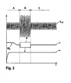
- the engine control unit 18 evaluates the results of the rotational speed measurement of the internal combustion engine 1 in block 204. Increases the rough running of the internal combustion engine 1 due to the ignition angle adjustment, that is, the vibration amplitude of the internal combustion engine 1 is larger, as in FIG. 3 , it is assumed that the internal combustion engine 1 is active and at least one cylinder operates without misfiring.
- the internal combustion engine is turned off in block 205.
- FIG. 3 in the upper diagram, the rotational noise n LR of the internal combustion engine 1 detected by the rotational speed measurement is shown.
- the uneven running in the form of the rotational speed in the region A has an approximately constant average value n LR .
- a torque reserve M R is constructed in the same area A in order to achieve an increase in torque before the activation of the function by an advance of the ignition can.
- the speed n which is displayed to the driver, stabilizes after starting at a constant level.
Landscapes
- Engineering & Computer Science (AREA)
- Chemical & Material Sciences (AREA)
- Combustion & Propulsion (AREA)
- Transportation (AREA)
- Mechanical Engineering (AREA)
- Automation & Control Theory (AREA)
- Physics & Mathematics (AREA)
- Mathematical Physics (AREA)
- Combined Controls Of Internal Combustion Engines (AREA)
- Hybrid Electric Vehicles (AREA)
- Control Of Vehicle Engines Or Engines For Specific Uses (AREA)
Description
- Verfahren zur Erkennung eines laufenden Verbrennungsmotors bei einem Hybridfahrzeug, bei welchem der Verbrennungsmotor als erstes Antriebsaggregat und ein zweites Antriebsaggregat einen Beitrag zum Antrieb des Hybridfahrzeuges leisten sowie eine Vorrichtung zur Durchführung des Verfahrens.
- Fahrzeuge mit einer hybriden Antriebsstruktur weisen einen Verbrennungsmotor und als zweites Antriebsaggregat meistens einen Elektromotor auf. So kann das Antriebsmoment während des Fahrbetriebes des Hybridfahrzeuges von beiden Antriebsaggregaten aufgebracht werden.
- Treten bei dem Verbrennungsmotor Fehler auf, machen sich diese durch Aussetzer auf den Zylindern des Verbrennungsmotors bemerkbar.
- Dauerhafte Aussetzer auf allen Zylindern des Verbrennungsmotors fallen bei einem Hybridfahrzeug nicht weiter auf, da das zweite Antriebsaggregat den Fahrbetrieb des Hybridfahrzeuges weiter gewährleistet. Mittels bekannter Laufunruheverfahren werden dauerhafte Aussetzer auf allen Zylindern nicht erkannt, da die Laufunruhe optimal ist. Alle Zylinder liefern eine gleich lange Segmentzeit.
- Aus der
DE 10 2006 012 868 A1 ist ein Verfahren zur Diagnose von Aussetzern einer Brennkraftmaschine bekannt, die gemeinsam mit einem Elektromotor in einem Hybridfahrzeug angeordnet ist. Dabei werden die Signale der Steuerung des Verbrennungsmotors mit den Signalen des Elektromotors verkoppelt, so dass mit diesen Signalen eine Diagnose des Verbrennungsmotors hinsichtlich des Auftretens von Verbrennungsaussetzern Mittels einer Schwingungsanalyse durchgeführt werden kann.EP 1 852 594 A1 beschreibt ein Verfahren nach dem Oberbegriff des Anspruchs 1. - Das erfindungsgemäße Verfahren zur Erkennung eines laufenden Verbrennungsmotors bei einem Hybridfahrzeug mit den Merkmalen des Anspruchs 1 weist den Vorteil auf, dass ein Verbrennungsmotor im Aussetzerbetrieb auf allen Zylindern ohne Zusatzkomponenten erkannt werden kann, wodurch eine sehr kostengünstige Analyse des Verhaltens des Verbrennungsmotors möglich ist. Durch ein an sich vorhandenes Motorsteuergerät, welches den Betrieb des Verbrennungsmotors steuert und regelt, wird aktiv ein Störsignal in den laufenden Betriebsablauf des Verbrennungsmotors eingebracht und die Reaktion des Verbrennungsmotors auf dieses Störsignal ausgewertet, wobei bei einer ausbleibenden Reaktion des Verbrennungsmotors auf das Störsignal darauf geschlossen wird, dass der Verbrennungsmotor nicht arbeitet.
- In einer Weiterbildung der Erfindung wird mindestens ein Verbrennungsparameter des Verbrennungsmotors geändert und eine Laufunruhe des Verbrennungsmotors überwacht, wobei bei Ausbleiben einer Veränderung der Laufunruhe infolge der Änderung des Verbrennungsparameters darauf geschlossen wird, dass dauerhafte Aussetzer auf allen Zylindern des Verbrennungsmotors auftreten. Durch die aktive Veränderung des Verbrennungsparameters des Verbrennungsmotors wird eine erhöhte Laufunruhe erzwungen, die ausgewertet wird. Läuft der Verbrennungsmotor nicht selbständig, wie es bei dauerhaften Aussetzern auf allen Zylindern der Fall ist, wird der Verbrennungsmotor auf die Veränderung der Verbrennungsparameter nicht reagieren. Das bedeutet, dass keine erhöhten Laufunruheaktivitäten nachweisbar sind, was somit als Fehler erkannt wird.
- In einer zusätzlichen Variante wird die Störgröße verstärkt. Damit wird eine zusätzliche Gewissheit darüber erreicht, dass keine Verbrennungen stattfinden. Eine vorzeitige ungerechtfertigte Abschaltung der Einspritzung wird somit vermieden. Mittels dieser einfachen Diagnostik kann der Verbrennungsmotor unverzüglich abgeschaltet werden, um zu verhindern, dass der unverbrannte Kraftstoff auf den heißen Katalysator trifft. Vorteilhafterweise wird als Verbrennungsparameter der Zündwinkel mindestens eines Zylinders des Verbrennungsmotors aktiv verstellt. Eine aktive Verstellung des Zündwinkels ist einfach und schnell möglich. Der Einfluss auf eine Verschlechterung des Abgases durch den Verstellbereich kann dabei begrenzt werden.
- Um in der Summe eine Neutralität zum Antriebsmoment des Hybridfahrzeuges zu gewährleisten, werden die Zündwinkel der Zylinder so eingestellt, dass bei einer vorgegebenen Anzahl von Zylindern eine verzögerte Zündung eintritt, während bei einer gleichen Anzahl von Zylindern eine vorzeitige Zündung auftritt. Diese kurzzeitige ungleiche Einstellung der Antriebsmomente der einzelnen Zylinder führt bei einem laufenden Verbrennungsmotor zu einer Erhöhung der Laufunruhe. Tritt diese Laufunruhe auf, wird der Verbrennungsmotor als laufend erkannt, unterbleibt die Laufunruhe ist der Verbrennungsmotor inaktiv.
- Um ein zuverlässiges und sicheres Ergebnis zu erlangen, wird die Verstellung der Zündwinkel mehrfach wiederholt.
- Als Verbrennungsparameter zur Erzielung der veränderten Laufunruhe wird eine Einspritzmenge kurzzeitig verstellt.
- In einer weiteren Ausgestaltung der Erfindung besteht eine Vorrichtung zur Erkennung eines laufenden Verbrennungsmotors bei einem Hybridfahrzeug, aus einem Verbrennungsmotor und einem zweiten Antriebaggregat, wobei der Verbrennungsmotor als erstes Antriebsaggregat und das zweite Antriebsaggregat gemeinsam einen Beitrag zum Antrieb des Hybridfahrzeuges leisten. Um im Hybridbetrieb des Fahrzeuges sicher festzustellen, ob der Verbrennungsmotor läuft, sind Mittel vorhanden, die aktiv ein Störsignal in den laufenden Betriebsablauf des Verbrennungsmotors einbringen und die Reaktion des Verbrennungsmotors auf dieses Störsignal auswerten, wobei bei einer ausbleibenden Reaktion des Verbrennungsmotors auf das Störsignal darauf geschlossen wird, dass der Verbrennungsmotor nicht arbeitet. Durch Änderung der Software im Motorsteuergerät kann ein solches Störsignal leicht erzeugt werden, wodurch das Fehlverhalten des Verbrennungsmotors erkannt wird, ohne dass weitere Komponenten benötigt werden.
- In einer Ausgestaltung der Erfindung ändern die Mittel mindestens einen Verbrennungsparameter des Verbrennungsmotors und überwachen eine Laufunruhe des Verbrennungsmotors, wobei bei Ausbleiben der Veränderung der Laufunruhe darauf geschlossen wird, dass dauerhafte Aussetzer auf allen Zylindern des Verbrennungsmotors auftreten. Reagiert der Verbrennungsmotor nicht auf die Änderung des Verbrennungsparameters, wird dies als Fehler erkannt und festgestellt, dass der Verbrennungsmotor nicht arbeitet.
- In einer einfachen und besonders kostengünstigen Ausführung wird die Laufunruhe des Verbrennungsmotors durch einen Drehzahlmesser überwacht.
- Die Erfindung lässt zahlreiche Ausführungsformen zu. Eine davon soll anhand der in der Zeichnung dargestellten Figuren näher erläutert werden.
- Es zeigt:
- Figur 1:
- Prinzipdarstellung eines Fahrzeuges mit Hybridantrieb
- Figur 2:
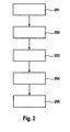
- schematisches Ablaufdiagramm eines Ausführungsbeispieles des erfindungsgemäßen Verfahrens
- Figur 3:
- Darstellung der Laufunruhe über dem Zündwinkel und der Zeit
-
Figur 1 zeigt eine Prinzipdarstellung für ein Fahrzeug mit einem Hybridantrieb. Der Hybridantrieb wird von einem Verbrennungsmotor 1 als erste Antriebseinheit und einem Elektromotor 2 als zweite Antriebseinheit gebildet. - Der Verbrennungsmotor 1, in diesem Falle ein 4-Takt-Ottomotor, ist über den Antriebsstrang 3 mit dem Getriebe 4 verbunden, welches wiederum über das Differential 5 auf die Radachse 6 zum Antrieb des Rades 7 führt.
- Der Elektromotor 2 ist über einen eigenen Antriebsstrang 8 mit dem Getriebe 4 verbünden und trägt damit zum Antrieb der Räder 7 und zum Gesamtdrehmoment des Fahrzeuges bei. Darüber hinaus verfügt der Elektromotor 2 über ein eigenes Elektromotorsteuergerät 9, welches an einen Hybrid CAN-Bus 10 angeschlossen ist, über welchen alle die Steuergeräte miteinander kommunizieren, die Einfluss auf den hybridspezifischen Fahrbetrieb des Fahrzeuges haben. Dazu gehört unter anderem das Batteriemanagementsystem 11 der Hochvoltbatterie 12. Die Hochvoltbatterie 12 ist mit dem Elektromotor 2 verbunden und versorgt diesen mit elektrischer Energie.
- Ein Fahrzeugsteuergerät 13 kommuniziert über den Hybrid CAN Bus 10 mit dem daran angeschlossenen Elektromotorsteuergerät 9, und dem Batteriemanagementsystem 11. Darüber hinaus ist es über den CAN Bus 14 u. a. mit einem ESP-Steuergerät 15 und anderen nicht weiter dargestellten Steuergeräten der Fahrzeugsicherheits- und Fahrerassistenzsysteme des Fahrzeuges verbunden.
- Über ein Gateway 16 steht der CAN Bus 14 mit einem Gateway CAN Bus 17 in Verbindung, über welchen die einzelnen Bussysteme des Fahrzeuges miteinander kommunizieren.
- Das Motorsteuergerät 18 des Verbrennungsmotors 1 ist über den Gateway-CAN Bus 17 und den CAN Bus 14 mit dem Fahrzeugsteuergerät 13 verbunden.
- Das Fahrzeugsteuergerät 13 ist mit Drehzahlgebern 19 und 20 verbunden, von welchem das Fahrzeugsteuergerät 13 Informationen über die aktuellen Betriebsparameter des Fahrzeugbetriebes erhält.
- Bei der vorliegenden Anordnung wird das für den Abtrieb relevante Drehmoment sowohl vom Verbrennungsmotor 1 als auch vom Elektromotor 2 aufgebracht.
- Anhand von
Figur 2 soll nun eine mögliche Ausführungsform der Erfindung erläutert werden, mittels welcher festgestellt werden soll, ob der Verbrennungsmotor 1 im Betrieb ist und einen Beitrag zum Antrieb des Hybridfahrzeuges leistet. - Im Block 201 wird davon ausgegangen, dass nach dem Motorstart sowohl der Verbrennungsmotor 1 als auch der Elektromotor 2 in Betrieb sind und beide ein Antriebsmoment an das Hybridfahrzeug abgeben.
- Im Block 202 wird durch das Motorsteuergerät 18 der Zündwinkel des Verbrennungsmotors 1 aktiv verstellt. Der Verbrennungsmotor 1 weist 4 Zylinder auf, wovon 2 Zylinder so verstellt werden, dass eine spätere Zündung als im Normalfall (optimaler Zündwinkel) erfolgt, was bedeutet, dass von diesen beiden Zylindern nur ein begrenztes Antriebsmoment an das Fahrzeug weitergegeben wird. Die beiden verbleibenden Zylinder werden so verstellt, dass die Zündung nach vorn verschoben wird, was zur Folge hat, dass ein größeres Antriebsmoment an das Fahrzeug abgegeben wird. Hinsichtlich des Antriebsmomentes wird durch die beschriebene Verstellung des Zündwinkels an den vier Zylindern eine gewisse Neutralität erreicht, so dass die Verstellung des Zündwinkels am Antriebsverhalten des Fahrzeuges nicht nachweisbar ist.
- Im Block 203 wird nun überwacht, ob diese kurzzeitige ungleiche Einstellung der Momente der vier Einzelzylinder zu einer Erhöhung der Laufunruhe des Verbrennungsmotors 1 führt, was durch den Drehzahlgeber 19 gemessen und an das Motorsteuergerät 18 weitergegeben wird. Die Laufunruhe äußert sich in einem nicht ganz gleichmäßigen Drehzahlsignal.
- Das Motorsteuergerät 18 wertet im Block 204 die Ergebnisse der Drehzahlmessung des Verbrennungsmotors 1 aus. Erhöht sich die Laufunruhe des Verbrennungsmotors 1 infolge der Zündwinkelverstellung, das heißt die Schwingungsamplitude des Verbrennungsmotors 1 wird größer, wie es in
Figur 3 , dargestellt ist, wird davon ausgegangen, dass der Verbrennungsmotor 1 aktiv ist und wenigstens ein Zylinder ohne Zündaussetzer arbeitet. - Bleibt die Drehzahlmessung nach der Verstellung der Zündwinkel aber konstant, wird darauf erkannt, dass ein Fehler vorliegt und der Verbrennungsmotor 1 nicht arbeitet, was damit gleichzusetzen ist, dass er auf allen Zylindern dauerhafte Aussetzer hat.
- Wird ein solcher Fehler erkannt, wird im Block 205 der Verbrennungsmotor abgeschaltet.
- In
Figur 3 ist in der oberen Darstellung die durch die Drehzahlmessung detektierte Laufunruhe nLR des Verbrennungsmotors 1 dargestellt. In der mittleren Darstellung ist der Zündwinkel δ und in der unteren Darstellung die Drehzahl n, wie sie dem Fahrer durch einen Drehzahlmesser im Kraftfahrzeug angezeigt wird, gezeigt. Alle drei Darstellungen sind über der Zeit t dargestellt. - Zum Zeitpunkt des Starts des Verbrennungsmotors 1 weist die Laufunruhe in Form der Drehzahl im Bereich A einen annähernd konstanten mittleren Wert nLR auf. Beim Zündwinkel δ wird im selben Bereich A eine Drehmomentenreserve MR aufgebaut, um vor der Aktivierung der Funktion durch eine Frühverstellung der Zündung auch eine Momentenerhöhung erzielen zu können. Die Drehzahl n, welche dem Fahrer angezeigt wird, stabilisiert sich nach dem Start auf einem konstanten Niveau.
- Im Abschnitt B werden, wie beschrieben, zwei Zylinder spät verstellt (Kurve v) und zwei Zylinder früh verstellt (Kurve w). Diese ungleiche Einstellung der Momente der einzelnen Zylinder führt zu einer Erhöhung der Laufunruhe des Motors, also der Drehzahl nLR. Tritt eine solche Erhöhung auf, ist der Verbrennungsmotor aktiv.
- Nach der aktiven Veränderung des Zündwinkels wird zum normalen Betriebszustand des Verbrennungsmotors 1 im Bereich C zurückgekehrt.
Der Fahrer nimmt diese Laufunruhe über die ihm angezeigte Drehzahl nicht wahr.
Claims (8)
- Verfahren zur Erkennung eines laufenden Verbrennungsmotors (1) bei einem Hybridfahrzeug, bei welchem der Verbrennungsmotor (1) als erstes Antriebsaggregat und ein zweites Antriebsaggregat (2) einen Beitrag zum Antrieb des Hybridfahrzeugs leisten, wobei aktiv ein Störsignal in den laufenden Betriebsablauf des Verbrennungsmotors (1) eingebracht wird und die Reaktion des Verbrennungsmotors (1) auf dieses Störsignal ausgewertet wird, wobei bei einer ausbleibenden Reaktion des Verbrennungsmotors (1) darauf geschlossen wird, dass der Verbrennungsmotor (1) nicht arbeitet, dadurch gekennzeichnet, dass mindestens ein Verbrennungsparameter (5) des Verbrennungsmotors (1) geändert wird und eine Laufunruhe (nLR) des Verbrennungsmotors (1) überwacht wird, wobei bei Ausbleiben einer Veränderung der Laufunruhe (nLR) infolge der Änderung des Verbrennungsparameters (δ) darauf geschlossen wird, dass dauerhafte Aussetzer auf allen Zylindern des Verbrennungsmotors (1) auftreten.
- Verfahren nach Anspruch 1, dadurch gekennzeichnet, dass als Verbrennungsparameter der Zündwinkel (δ) mindestens eines Zylinders des Verbrennungsmotors (1) aktiv verstellt wird.
- Verfahren nach Anspruch 2, dadurch gekennzeichnet, dass der Zündwinkel (δ) der Zylinder so eingestellt wird, dass bei einer vorgegebenen Anzahl von Zylindern eine verzögerte Zündung eintritt, während bei einer gleichen Anzahl von Zylindern eine vorzeitige Zündung auftritt.
- Verfahren nach Anspruch 3, dadurch gekennzeichnet, dass die Verstellung der Zündwinkel (δ) mehrfach wiederholt wird.
- Verfahren nach Anspruch 1, dadurch gekennzeichnet, dass als Verbrennungsparameter eine Einspritzmenge verstellt wird.
- Verfahren nach Anspruch 1, dadurch gekennzeichnet, dass das Störsignal verstärkt wird oder die Häufigkeit des Auftretens des Störsignals erhöht wird.
- Vorrichtung zur Erkennung eines laufenden Verbrennungsmotors bei einem Hybridfahrzeug, bei welchem der Verbrennungsmotor (1) als erstes Antriebsaggregat und ein zweites Antriebsaggregat (2) einen Beitrag zum Antrieb des Hybridfahrzeugs leisten, wobei Mittel (18) vorhanden sind, die aktiv ein Störsignal in den laufenden Betriebsablauf des Verbrennungsmotors (1) einbringen und die Reaktion des Verbrennungsmotors (1) auf dieses Störsignal auswerten, wobei bei einer ausbleibenden Reaktion des Verbrennungsmotors (1) darauf geschlossen wird, dass der Verbrennungsmotor (1) nicht arbeitet, dadurch gekennzeichnet, dass die Mittel (18) mindestens einen Verbrennungsparameter (5) des Verbrennungsmotors (1) ändern und eine Laufunruhe (nLR) des Verbrennungsmotors (1) überwachen, wobei bei Ausbleiben einer Veränderung der Laufunruhe (nLR) darauf geschlossen wird, dass dauerhafte Aussetzer auf allen Zylindern des Verbrennungsmotors (1) auftreten.
- Vorrichtung nach Anspruch 7, dadurch gekennzeichnet, dass ein Drehzahlmesser (19) die Laufunruhe (nLR) des Verbrennungsmotors (1) überwacht.
Applications Claiming Priority (2)
| Application Number | Priority Date | Filing Date | Title |
|---|---|---|---|
| DE102008041108A DE102008041108A1 (de) | 2008-08-07 | 2008-08-07 | Verfahren und Vorrichtung zur Erkennung eines laufenden Verbrennungsmotors bei einem Hybridfahrzeug |
| PCT/EP2009/058748 WO2010015483A2 (de) | 2008-08-07 | 2009-07-09 | Verfahren und vorrichtung zur erkennung eines laufenden verbrennungsmotors bei einem hybridfahrzeug |
Publications (2)
| Publication Number | Publication Date |
|---|---|
| EP2321165A2 EP2321165A2 (de) | 2011-05-18 |
| EP2321165B1 true EP2321165B1 (de) | 2015-09-09 |
Family
ID=41445517
Family Applications (1)
| Application Number | Title | Priority Date | Filing Date |
|---|---|---|---|
| EP09780374.6A Not-in-force EP2321165B1 (de) | 2008-08-07 | 2009-07-09 | Verfahren und vorrichtung zur erkennung eines laufenden verbrennungsmotors bei einem hybridfahrzeug |
Country Status (5)
| Country | Link |
|---|---|
| US (1) | US9527376B2 (de) |
| EP (1) | EP2321165B1 (de) |
| CN (1) | CN102171082B (de) |
| DE (1) | DE102008041108A1 (de) |
| WO (1) | WO2010015483A2 (de) |
Families Citing this family (8)
| Publication number | Priority date | Publication date | Assignee | Title |
|---|---|---|---|---|
| DE102010039800A1 (de) * | 2010-08-26 | 2012-03-01 | Robert Bosch Gmbh | Verfahren und Vorrichtung zur Erkennung des selbständigen Laufens eines Verbrennungsmotors |
| DE102010062261A1 (de) | 2010-12-01 | 2012-06-06 | Robert Bosch Gmbh | Verfahren und Steuergerät zum Betreiben eines Kraftfahrzeuges |
| DE102011003581A1 (de) | 2011-02-03 | 2012-08-09 | Robert Bosch Gmbh | Verfahren und Vorrichtung zur Überwachung der bestimmungsgemäßen Funktion mindestens einer ersten und einer zweiten Komponente eines Fahrzeugantriebsstrangs |
| DE102011108226A1 (de) * | 2011-07-22 | 2013-01-24 | Audi Ag | Verfahren zum Betreiben eines Antriebssystems sowie Antriebssystem |
| DE102014202032A1 (de) * | 2014-02-05 | 2015-08-06 | Robert Bosch Gmbh | Verfahren zur Überwachung von Antrieben |
| DE102014221293A1 (de) | 2014-10-21 | 2016-04-21 | Volkswagen Aktiengesellschaft | Verfahren und Steuervorrichtung zum Erkennen eines Verbrennungsvorgangs einer Verbrennungskraftmaschine eines Hybridfahrzeugs |
| DE102016202556A1 (de) * | 2016-02-18 | 2017-08-24 | Volkswagen Aktiengesellschaft | Verfahren und Steuervorrichtung zum Erkennen während eines Betriebs eines Hybridfahrzeugs, ob in einer Verbrennungskraftmaschine des Hybridfahrzeugs eine Verbrennung stattfindet |
| DE102018209223A1 (de) | 2018-06-11 | 2019-12-12 | Robert Bosch Gmbh | Verfahren zum Betreiben einer Antriebsanordnung für ein Kraftfahrzeug, Antriebsanordnung und Kraftfahrzeug |
Family Cites Families (6)
| Publication number | Priority date | Publication date | Assignee | Title |
|---|---|---|---|---|
| EP1143134B1 (de) * | 1998-12-24 | 2012-08-08 | Toyota Jidosha Kabushiki Kaisha | Detektor für die leistungsabgabe einer brennkraftmaschine |
| US6925982B2 (en) * | 2002-06-04 | 2005-08-09 | Ford Global Technologies, Llc | Overall scheduling of a lean burn engine system |
| JP4525538B2 (ja) * | 2005-02-24 | 2010-08-18 | トヨタ自動車株式会社 | 内燃機関の失火判定装置および失火判定方法 |
| JP4123254B2 (ja) * | 2005-07-27 | 2008-07-23 | トヨタ自動車株式会社 | 内燃機関の失火判定装置および内燃機関の失火判定方法 |
| DE102006012868B4 (de) | 2006-03-21 | 2021-02-04 | Robert Bosch Gmbh | Verdrängerpumpe |
| DE102008041406B4 (de) * | 2008-08-21 | 2019-07-18 | Robert Bosch Gmbh | Verfahren und Vorrichtung zur Diagnose einer Brennkraftmaschine, Computerprogramm und Computerprogrammprodukt |
-
2008
- 2008-08-07 DE DE102008041108A patent/DE102008041108A1/de not_active Withdrawn
-
2009
- 2009-07-09 US US12/737,668 patent/US9527376B2/en not_active Expired - Fee Related
- 2009-07-09 EP EP09780374.6A patent/EP2321165B1/de not_active Not-in-force
- 2009-07-09 CN CN200980139493.4A patent/CN102171082B/zh active Active
- 2009-07-09 WO PCT/EP2009/058748 patent/WO2010015483A2/de not_active Ceased
Also Published As
| Publication number | Publication date |
|---|---|
| US9527376B2 (en) | 2016-12-27 |
| WO2010015483A2 (de) | 2010-02-11 |
| DE102008041108A1 (de) | 2010-02-11 |
| CN102171082B (zh) | 2015-02-11 |
| WO2010015483A3 (de) | 2010-06-10 |
| US20110208401A1 (en) | 2011-08-25 |
| CN102171082A (zh) | 2011-08-31 |
| EP2321165A2 (de) | 2011-05-18 |
Similar Documents
| Publication | Publication Date | Title |
|---|---|---|
| WO2010015483A2 (de) | Verfahren und vorrichtung zur erkennung eines laufenden verbrennungsmotors bei einem hybridfahrzeug | |
| DE102007013336B4 (de) | Verfahren zum Steuern des Bewegungsdrehmoments für den Endantrieb eines Fahrzeugs zum Umgang mit Ruckeln unter Verwendung einer multivariablen aktiven Endantriebsdämpfung | |
| EP2609411B1 (de) | Verfahren zum detektieren von fehlzündungen in verbrennungsmotoren und detektierungsvorrichtung | |
| EP2670644B1 (de) | VERFAHREN UND VORRICHTUNG ZUR ÜBERWACHUNG DER BESTIMMUNGSGEMÄßEN FUNKTION MINDESTENS EINER ERSTEN UND EINER ZWEITEN KOMPONENTE EINES FAHRZEUGANTRIEBSSTRANGS | |
| DE112013002307T5 (de) | Diagnosesystem und Diagnoseverfahren für eine Verbrennungskraftmaschine | |
| DE102008046524A1 (de) | Verfahren und Vorrichtung zum Überwachen eines Abtriebsdrehzahlsensors während des Betriebs eines elektromechanischen Getriebes | |
| DE102007042077A1 (de) | Steuersystemarchitektur für einen Hybridantriebsstrang | |
| DE102010032352B4 (de) | System zum Überwachen der Stabiliät eines Hybridantriebsstrangs | |
| WO2009037046A1 (de) | Verfahren und steuerung zur funktionsüberwachung eines verbrennungsmotors | |
| DE112010001460T5 (de) | Fahrzeuginterne Steuervorrichtung | |
| DE102008008207A1 (de) | Verfahren zum ausfallsicheren Betreiben eines Hybridfahrzeugs zum kontrollierten Hervorrufen von einer einen Notlauf des Fahrzeugs ermöglichenden Ersatzmaßnahme und Vorrichtung zum Durchführen dieses Verfahrens | |
| DE4021985A1 (de) | Verfahren zum pruefen der funktion eines antriebsrad-schlupfsteuersystems | |
| DE10206474B4 (de) | Verfahren und Vorrichtung zur Erfassung der Reibung in einer elektrischen oder elektromechanischen Lenkvorrichtung eines Kraftfahrzeugs | |
| DE102006050100B4 (de) | Straßenunebenheits-Detektionssystem | |
| DE102006050597A1 (de) | Fehlzündungsdetektionssystem für einen Motor mit bedarfsabhängigem Hubraum | |
| DE102005040780B4 (de) | Verfahren und Motorsteuerungsgerät zur Verfügbarkeitserhöhung von Kraftfahrzeugmotoren | |
| EP0941163B1 (de) | Vorrichtung und verfahren zur erzeugung eines fehlersignals bei einem kraftfahrzeug | |
| DE102014224030A1 (de) | Verfahren zur Erkennung eines Längsruckelns eines Kraftfahrzeugs | |
| DE102010039800A1 (de) | Verfahren und Vorrichtung zur Erkennung des selbständigen Laufens eines Verbrennungsmotors | |
| EP2786110A2 (de) | Verfahren zur überwachung des zustands eines einen elektromotor auf einer welle führenden lagers | |
| DE102013218837B4 (de) | Verfahren und Vorrichtung zur Diagnose von Raddrehzahlsensoren eines Kraftfahrzeuges | |
| DE102021202655B3 (de) | Verfahren und Vorrichtung zur Diagnose einer Brennkraftmaschine eines Antriebsstrangs | |
| EP0529274A1 (de) | Verfahren zur Steuerung von betriebsparameterabhängigen und sich zyklisch wiederholenden Betriebsvorgängen von Brennkraftmaschinen | |
| WO2023217425A1 (de) | Verfahren zum betreiben eines kraftfahrzeugs sowie entsprechendes kraftfahrzeug | |
| DE112014002490T5 (de) | Analyse einer Funktion für mindestens ein System bei einem Verbrennungsmotor |
Legal Events
| Date | Code | Title | Description |
|---|---|---|---|
| PUAI | Public reference made under article 153(3) epc to a published international application that has entered the european phase |
Free format text: ORIGINAL CODE: 0009012 |
|
| 17P | Request for examination filed |
Effective date: 20110307 |
|
| AK | Designated contracting states |
Kind code of ref document: A2 Designated state(s): AT BE BG CH CY CZ DE DK EE ES FI FR GB GR HR HU IE IS IT LI LT LU LV MC MK MT NL NO PL PT RO SE SI SK SM TR |
|
| AX | Request for extension of the european patent |
Extension state: AL BA RS |
|
| DAX | Request for extension of the european patent (deleted) | ||
| GRAP | Despatch of communication of intention to grant a patent |
Free format text: ORIGINAL CODE: EPIDOSNIGR1 |
|
| RIC1 | Information provided on ipc code assigned before grant |
Ipc: B60W 10/08 20060101ALI20150312BHEP Ipc: B60W 10/06 20060101ALI20150312BHEP Ipc: B60W 20/00 20060101AFI20150312BHEP Ipc: B60K 6/48 20071001ALI20150312BHEP |
|
| INTG | Intention to grant announced |
Effective date: 20150327 |
|
| GRAS | Grant fee paid |
Free format text: ORIGINAL CODE: EPIDOSNIGR3 |
|
| GRAA | (expected) grant |
Free format text: ORIGINAL CODE: 0009210 |
|
| AK | Designated contracting states |
Kind code of ref document: B1 Designated state(s): AT BE BG CH CY CZ DE DK EE ES FI FR GB GR HR HU IE IS IT LI LT LU LV MC MK MT NL NO PL PT RO SE SI SK SM TR |
|
| REG | Reference to a national code |
Ref country code: GB Ref legal event code: FG4D Free format text: NOT ENGLISH |
|
| REG | Reference to a national code |
Ref country code: AT Ref legal event code: REF Ref document number: 747860 Country of ref document: AT Kind code of ref document: T Effective date: 20150915 Ref country code: CH Ref legal event code: EP |
|
| REG | Reference to a national code |
Ref country code: IE Ref legal event code: FG4D Free format text: LANGUAGE OF EP DOCUMENT: GERMAN |
|
| REG | Reference to a national code |
Ref country code: DE Ref legal event code: R096 Ref document number: 502009011564 Country of ref document: DE |
|
| REG | Reference to a national code |
Ref country code: NL Ref legal event code: MP Effective date: 20150909 |
|
| PG25 | Lapsed in a contracting state [announced via postgrant information from national office to epo] |
Ref country code: NO Free format text: LAPSE BECAUSE OF FAILURE TO SUBMIT A TRANSLATION OF THE DESCRIPTION OR TO PAY THE FEE WITHIN THE PRESCRIBED TIME-LIMIT Effective date: 20151209 Ref country code: LT Free format text: LAPSE BECAUSE OF FAILURE TO SUBMIT A TRANSLATION OF THE DESCRIPTION OR TO PAY THE FEE WITHIN THE PRESCRIBED TIME-LIMIT Effective date: 20150909 Ref country code: LV Free format text: LAPSE BECAUSE OF FAILURE TO SUBMIT A TRANSLATION OF THE DESCRIPTION OR TO PAY THE FEE WITHIN THE PRESCRIBED TIME-LIMIT Effective date: 20150909 Ref country code: FI Free format text: LAPSE BECAUSE OF FAILURE TO SUBMIT A TRANSLATION OF THE DESCRIPTION OR TO PAY THE FEE WITHIN THE PRESCRIBED TIME-LIMIT Effective date: 20150909 Ref country code: GR Free format text: LAPSE BECAUSE OF FAILURE TO SUBMIT A TRANSLATION OF THE DESCRIPTION OR TO PAY THE FEE WITHIN THE PRESCRIBED TIME-LIMIT Effective date: 20151210 |
|
| REG | Reference to a national code |
Ref country code: LT Ref legal event code: MG4D |
|
| PG25 | Lapsed in a contracting state [announced via postgrant information from national office to epo] |
Ref country code: HR Free format text: LAPSE BECAUSE OF FAILURE TO SUBMIT A TRANSLATION OF THE DESCRIPTION OR TO PAY THE FEE WITHIN THE PRESCRIBED TIME-LIMIT Effective date: 20150909 Ref country code: ES Free format text: LAPSE BECAUSE OF FAILURE TO SUBMIT A TRANSLATION OF THE DESCRIPTION OR TO PAY THE FEE WITHIN THE PRESCRIBED TIME-LIMIT Effective date: 20150909 Ref country code: SE Free format text: LAPSE BECAUSE OF FAILURE TO SUBMIT A TRANSLATION OF THE DESCRIPTION OR TO PAY THE FEE WITHIN THE PRESCRIBED TIME-LIMIT Effective date: 20150909 |
|
| PG25 | Lapsed in a contracting state [announced via postgrant information from national office to epo] |
Ref country code: NL Free format text: LAPSE BECAUSE OF FAILURE TO SUBMIT A TRANSLATION OF THE DESCRIPTION OR TO PAY THE FEE WITHIN THE PRESCRIBED TIME-LIMIT Effective date: 20150909 |
|
| PG25 | Lapsed in a contracting state [announced via postgrant information from national office to epo] |
Ref country code: CZ Free format text: LAPSE BECAUSE OF FAILURE TO SUBMIT A TRANSLATION OF THE DESCRIPTION OR TO PAY THE FEE WITHIN THE PRESCRIBED TIME-LIMIT Effective date: 20150909 Ref country code: IS Free format text: LAPSE BECAUSE OF FAILURE TO SUBMIT A TRANSLATION OF THE DESCRIPTION OR TO PAY THE FEE WITHIN THE PRESCRIBED TIME-LIMIT Effective date: 20160109 Ref country code: EE Free format text: LAPSE BECAUSE OF FAILURE TO SUBMIT A TRANSLATION OF THE DESCRIPTION OR TO PAY THE FEE WITHIN THE PRESCRIBED TIME-LIMIT Effective date: 20150909 Ref country code: SK Free format text: LAPSE BECAUSE OF FAILURE TO SUBMIT A TRANSLATION OF THE DESCRIPTION OR TO PAY THE FEE WITHIN THE PRESCRIBED TIME-LIMIT Effective date: 20150909 |
|
| PG25 | Lapsed in a contracting state [announced via postgrant information from national office to epo] |
Ref country code: PT Free format text: LAPSE BECAUSE OF FAILURE TO SUBMIT A TRANSLATION OF THE DESCRIPTION OR TO PAY THE FEE WITHIN THE PRESCRIBED TIME-LIMIT Effective date: 20160111 Ref country code: PL Free format text: LAPSE BECAUSE OF FAILURE TO SUBMIT A TRANSLATION OF THE DESCRIPTION OR TO PAY THE FEE WITHIN THE PRESCRIBED TIME-LIMIT Effective date: 20150909 Ref country code: RO Free format text: LAPSE BECAUSE OF FAILURE TO SUBMIT A TRANSLATION OF THE DESCRIPTION OR TO PAY THE FEE WITHIN THE PRESCRIBED TIME-LIMIT Effective date: 20150909 |
|
| REG | Reference to a national code |
Ref country code: DE Ref legal event code: R097 Ref document number: 502009011564 Country of ref document: DE |
|
| PLBE | No opposition filed within time limit |
Free format text: ORIGINAL CODE: 0009261 |
|
| STAA | Information on the status of an ep patent application or granted ep patent |
Free format text: STATUS: NO OPPOSITION FILED WITHIN TIME LIMIT |
|
| REG | Reference to a national code |
Ref country code: FR Ref legal event code: PLFP Year of fee payment: 8 |
|
| 26N | No opposition filed |
Effective date: 20160610 |
|
| PG25 | Lapsed in a contracting state [announced via postgrant information from national office to epo] |
Ref country code: DK Free format text: LAPSE BECAUSE OF FAILURE TO SUBMIT A TRANSLATION OF THE DESCRIPTION OR TO PAY THE FEE WITHIN THE PRESCRIBED TIME-LIMIT Effective date: 20150909 Ref country code: SI Free format text: LAPSE BECAUSE OF FAILURE TO SUBMIT A TRANSLATION OF THE DESCRIPTION OR TO PAY THE FEE WITHIN THE PRESCRIBED TIME-LIMIT Effective date: 20150909 |
|
| PG25 | Lapsed in a contracting state [announced via postgrant information from national office to epo] |
Ref country code: BE Free format text: LAPSE BECAUSE OF NON-PAYMENT OF DUE FEES Effective date: 20160731 |
|
| REG | Reference to a national code |
Ref country code: CH Ref legal event code: PL |
|
| PG25 | Lapsed in a contracting state [announced via postgrant information from national office to epo] |
Ref country code: MC Free format text: LAPSE BECAUSE OF FAILURE TO SUBMIT A TRANSLATION OF THE DESCRIPTION OR TO PAY THE FEE WITHIN THE PRESCRIBED TIME-LIMIT Effective date: 20150909 |
|
| PG25 | Lapsed in a contracting state [announced via postgrant information from national office to epo] |
Ref country code: LI Free format text: LAPSE BECAUSE OF NON-PAYMENT OF DUE FEES Effective date: 20160731 Ref country code: CH Free format text: LAPSE BECAUSE OF NON-PAYMENT OF DUE FEES Effective date: 20160731 |
|
| REG | Reference to a national code |
Ref country code: IE Ref legal event code: MM4A |
|
| REG | Reference to a national code |
Ref country code: FR Ref legal event code: PLFP Year of fee payment: 9 |
|
| PG25 | Lapsed in a contracting state [announced via postgrant information from national office to epo] |
Ref country code: IE Free format text: LAPSE BECAUSE OF NON-PAYMENT OF DUE FEES Effective date: 20160709 |
|
| PG25 | Lapsed in a contracting state [announced via postgrant information from national office to epo] |
Ref country code: LU Free format text: LAPSE BECAUSE OF NON-PAYMENT OF DUE FEES Effective date: 20160709 |
|
| REG | Reference to a national code |
Ref country code: AT Ref legal event code: MM01 Ref document number: 747860 Country of ref document: AT Kind code of ref document: T Effective date: 20160709 |
|
| PG25 | Lapsed in a contracting state [announced via postgrant information from national office to epo] |
Ref country code: AT Free format text: LAPSE BECAUSE OF NON-PAYMENT OF DUE FEES Effective date: 20160709 |
|
| PG25 | Lapsed in a contracting state [announced via postgrant information from national office to epo] |
Ref country code: HU Free format text: LAPSE BECAUSE OF FAILURE TO SUBMIT A TRANSLATION OF THE DESCRIPTION OR TO PAY THE FEE WITHIN THE PRESCRIBED TIME-LIMIT; INVALID AB INITIO Effective date: 20090709 Ref country code: CY Free format text: LAPSE BECAUSE OF FAILURE TO SUBMIT A TRANSLATION OF THE DESCRIPTION OR TO PAY THE FEE WITHIN THE PRESCRIBED TIME-LIMIT Effective date: 20150909 Ref country code: SM Free format text: LAPSE BECAUSE OF FAILURE TO SUBMIT A TRANSLATION OF THE DESCRIPTION OR TO PAY THE FEE WITHIN THE PRESCRIBED TIME-LIMIT Effective date: 20150909 |
|
| PG25 | Lapsed in a contracting state [announced via postgrant information from national office to epo] |
Ref country code: MK Free format text: LAPSE BECAUSE OF FAILURE TO SUBMIT A TRANSLATION OF THE DESCRIPTION OR TO PAY THE FEE WITHIN THE PRESCRIBED TIME-LIMIT Effective date: 20150909 Ref country code: TR Free format text: LAPSE BECAUSE OF FAILURE TO SUBMIT A TRANSLATION OF THE DESCRIPTION OR TO PAY THE FEE WITHIN THE PRESCRIBED TIME-LIMIT Effective date: 20150909 Ref country code: MT Free format text: LAPSE BECAUSE OF FAILURE TO SUBMIT A TRANSLATION OF THE DESCRIPTION OR TO PAY THE FEE WITHIN THE PRESCRIBED TIME-LIMIT Effective date: 20150909 |
|
| REG | Reference to a national code |
Ref country code: FR Ref legal event code: PLFP Year of fee payment: 10 |
|
| PG25 | Lapsed in a contracting state [announced via postgrant information from national office to epo] |
Ref country code: BG Free format text: LAPSE BECAUSE OF FAILURE TO SUBMIT A TRANSLATION OF THE DESCRIPTION OR TO PAY THE FEE WITHIN THE PRESCRIBED TIME-LIMIT Effective date: 20150909 |
|
| RIC2 | Information provided on ipc code assigned after grant |
Ipc: B60W 10/08 20060101ALI20150312BHEP Ipc: B60K 6/48 20071001ALI20150312BHEP Ipc: B60W 10/06 20060101ALI20150312BHEP Ipc: B60W 20/00 20160101AFI20150312BHEP |
|
| PGFP | Annual fee paid to national office [announced via postgrant information from national office to epo] |
Ref country code: FR Payment date: 20200727 Year of fee payment: 12 Ref country code: GB Payment date: 20200724 Year of fee payment: 12 |
|
| PGFP | Annual fee paid to national office [announced via postgrant information from national office to epo] |
Ref country code: IT Payment date: 20200731 Year of fee payment: 12 |
|
| GBPC | Gb: european patent ceased through non-payment of renewal fee |
Effective date: 20210709 |
|
| PG25 | Lapsed in a contracting state [announced via postgrant information from national office to epo] |
Ref country code: GB Free format text: LAPSE BECAUSE OF NON-PAYMENT OF DUE FEES Effective date: 20210709 |
|
| PG25 | Lapsed in a contracting state [announced via postgrant information from national office to epo] |
Ref country code: FR Free format text: LAPSE BECAUSE OF NON-PAYMENT OF DUE FEES Effective date: 20210731 |
|
| PG25 | Lapsed in a contracting state [announced via postgrant information from national office to epo] |
Ref country code: IT Free format text: LAPSE BECAUSE OF NON-PAYMENT OF DUE FEES Effective date: 20210709 |
|
| PGFP | Annual fee paid to national office [announced via postgrant information from national office to epo] |
Ref country code: DE Payment date: 20230922 Year of fee payment: 15 |
|
| REG | Reference to a national code |
Ref country code: DE Ref legal event code: R119 Ref document number: 502009011564 Country of ref document: DE |
|
| PG25 | Lapsed in a contracting state [announced via postgrant information from national office to epo] |
Ref country code: DE Free format text: LAPSE BECAUSE OF NON-PAYMENT OF DUE FEES Effective date: 20250201 |