EP2322072B1 - Lave-vaisselle doté d'un accumulateur thermique latent - Google Patents
Lave-vaisselle doté d'un accumulateur thermique latent Download PDFInfo
- Publication number
- EP2322072B1 EP2322072B1 EP11001364.6A EP11001364A EP2322072B1 EP 2322072 B1 EP2322072 B1 EP 2322072B1 EP 11001364 A EP11001364 A EP 11001364A EP 2322072 B1 EP2322072 B1 EP 2322072B1
- Authority
- EP
- European Patent Office
- Prior art keywords
- latent heat
- heat storage
- fluid
- heat
- vat
- Prior art date
- Legal status (The legal status is an assumption and is not a legal conclusion. Google has not performed a legal analysis and makes no representation as to the accuracy of the status listed.)
- Active
Links
Images

Classifications
-
- A—HUMAN NECESSITIES
- A47—FURNITURE; DOMESTIC ARTICLES OR APPLIANCES; COFFEE MILLS; SPICE MILLS; SUCTION CLEANERS IN GENERAL
- A47L—DOMESTIC WASHING OR CLEANING; SUCTION CLEANERS IN GENERAL
- A47L15/00—Washing or rinsing machines for crockery or tableware
- A47L15/42—Details
- A47L15/4291—Recovery arrangements, e.g. for the recovery of energy or water
-
- A—HUMAN NECESSITIES
- A47—FURNITURE; DOMESTIC ARTICLES OR APPLIANCES; COFFEE MILLS; SPICE MILLS; SUCTION CLEANERS IN GENERAL
- A47L—DOMESTIC WASHING OR CLEANING; SUCTION CLEANERS IN GENERAL
- A47L15/00—Washing or rinsing machines for crockery or tableware
- A47L15/42—Details
- A47L15/48—Drying arrangements
-
- Y—GENERAL TAGGING OF NEW TECHNOLOGICAL DEVELOPMENTS; GENERAL TAGGING OF CROSS-SECTIONAL TECHNOLOGIES SPANNING OVER SEVERAL SECTIONS OF THE IPC; TECHNICAL SUBJECTS COVERED BY FORMER USPC CROSS-REFERENCE ART COLLECTIONS [XRACs] AND DIGESTS
- Y02—TECHNOLOGIES OR APPLICATIONS FOR MITIGATION OR ADAPTATION AGAINST CLIMATE CHANGE
- Y02B—CLIMATE CHANGE MITIGATION TECHNOLOGIES RELATED TO BUILDINGS, e.g. HOUSING, HOUSE APPLIANCES OR RELATED END-USER APPLICATIONS
- Y02B30/00—Energy efficient heating, ventilation or air conditioning [HVAC]
- Y02B30/52—Heat recovery pumps, i.e. heat pump based systems or units able to transfer the thermal energy from one area of the premises or part of the facilities to a different one, improving the overall efficiency
-
- Y—GENERAL TAGGING OF NEW TECHNOLOGICAL DEVELOPMENTS; GENERAL TAGGING OF CROSS-SECTIONAL TECHNOLOGIES SPANNING OVER SEVERAL SECTIONS OF THE IPC; TECHNICAL SUBJECTS COVERED BY FORMER USPC CROSS-REFERENCE ART COLLECTIONS [XRACs] AND DIGESTS
- Y02—TECHNOLOGIES OR APPLICATIONS FOR MITIGATION OR ADAPTATION AGAINST CLIMATE CHANGE
- Y02B—CLIMATE CHANGE MITIGATION TECHNOLOGIES RELATED TO BUILDINGS, e.g. HOUSING, HOUSE APPLIANCES OR RELATED END-USER APPLICATIONS
- Y02B40/00—Technologies aiming at improving the efficiency of home appliances, e.g. induction cooking or efficient technologies for refrigerators, freezers or dish washers
Definitions
- the invention relates to a dishwasher with latent heat storage and a method for operating such a device.
- Out EP 2 193 741 is a dishwasher with a latent heat storage and a heat pump known.
- the process liquid is warmed up in the tub with the heat pump in a first phase of the process, the heat pump simultaneously extracts heat from the latent heat storage and this at least partially cools down below its phase transition temperature.
- the latent heat storage is thermally coupled to the tub by a heat coupling tank between the latent heat storage tank and tub is filled with water. As a result, a wall of the tub is cooled, whereby water condenses out of the process air. At the same time heat is transferred back into the latent heat storage.
- DE 37 41 652 be Plantt a device for drying dishes, in which the process air is funded by a latent heat storage. As a result, it is cooled to remove water. Then it is reheated.
- a first process phase heat is withdrawn from the latent heat store with the heat pump and supplied to the process liquid.
- the process liquid can be heated, for example, at the beginning of the main rinsing phase and / or the final rinse phase.
- the tub heat is removed and fed to the latent heat storage, whereby the process air can be dried.
- a fluid is circulated between a first area on or in the tub and a second area on or in the latent heat storage, ie circulated by pumping.
- the said fluid is a fluid which does not correspond to the process air, but e.g. to a liquid or another gas.
- Liquids are also understood to mean suspensions with solid fractions arranged in the liquid, such as, for example, a partially frozen-out liquid.
- the fluid must be conducted in a fluid circuit separated from the process air.
- This fluid circuit comprises a first heat exchanger, which is thermally coupled to the interior of the tub and a second heat exchanger, which is thermally coupled to the latent heat storage.
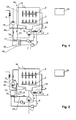
- the dishwasher after Fig. 1 has as a process room a tub 1 for receiving the items to be washed, such as crockery and cutlery, and the process fluid.
- a tub 1 for receiving the items to be washed, such as crockery and cutlery, and the process fluid.
- the items to be washed are supplied with process liquid, ie water with any additives, from spray devices, such as rotatable spray arms 2 and / or other nozzle arrangements.
- a process water circuit with a circulation pump 3 is provided on the tub 1, with which the process liquid from a sump 4 of the tub 1 can be conveyed through a line 12 to the spray devices 2.
- At the process water circuit may be provided a conventional heater (not shown) to heat the process water.
- the device has a fresh water valve 5, through which fresh process water, optionally via a treatment plant, such as. a desalination plant (not shown) to which tub 1 can be supplied.
- a treatment plant such as. a desalination plant (not shown) to which tub 1 can be supplied.
- a drain pump 6 is used for discharging process liquid from the tub 1.
- the device has a heat pump with a compressor 7, a condenser 8, an expansion valve 9 and an evaporator 10.
- the condenser 8 is thermally connected to the tub 1 or the process water circuit. In the present example, it is arranged on the line 12 and / or the feed pump 3. Alternatively or additionally, the capacitor 8 may be thermally coupled to the tub 1.
- the evaporator 10 is thermally coupled to a latent heat storage 14.
- the latent heat storage 14 is preferably designed as a tank in which a heat storage liquid is arranged.
- a heat storage liquid This may be, for example, water, or the heat storage fluid may at least partially consist of water. Water is preferred because of its high heat capacity and toxic safety.
- the tank for the heat storage liquid is preferably designed as a closed tank.
- a closed tank is to be understood as meaning a tank which does not communicate with the lines (such as inflow line, outflow line or circulation line) for the process liquid, so that the process liquid remains separate from the heat storage liquid.
- the closed tank may, for example, have openings which, for example, allow access to the heat storage fluid for the purpose of maintenance and transport.
- the said openings may be designed to be closable, or remain permanently open, for example for pressure equalization.
- the tank is provided with a fresh water supply and an outflow to keep the water in the tank regularly, e.g. after every 50 wash cycles or longer service life, automatically change so that high hygiene can be maintained and water loss (due, for example, to diffusion through hoses, etc.) can be counteracted.
- the dishwasher preferably also in this case has no means to lead water from the tub into the tank.
- the latent heat accumulator 14 is preferably arranged in a bottom region of the device.
- These heat coupling means comprise a pump 15 for circulating a fluid between a first region 16 on or in the tub 1 and a second region 17 on or in the latent heat storage 14.
- a first heat exchanger 18 is provided, and in the second region 17, a second heat exchanger 19.
- the fluid circuit further comprises a first conduit 21, in which the fluid with the pump 15 from the first to the second heat exchanger 18 and 19, respectively , as well as a second conduit 22, in which the fluid with the pump 15 at the same time from the second to the first heat exchanger 19 and 18, respectively.
- the latent heat accumulator 14 is arranged outside the tub 1 and at a distance therefrom, so that the tub 1 and the latent heat accumulator 14 are thermally separated from one another when the pump 15 and thus stationary fluid are switched off.
- the fluid in the fluid circuit contains a substantial portion of water, since this is toxic harmless, low corrosive and inexpensive.
- the fluid is composed so that it has a lower freezing point than the phase transition temperature of the latent heat accumulator 14, so that it can still be pumped around easily if the latent heat accumulator is partially or completely in its lower phase state.
- a gas can also be used as the fluid.
- the first heat exchanger 18 is designed as a tank or line system, which is arranged on a wall 23 of the tub 1, so that during drying of the items to be washed (see below) the moisture from the process air can condense on the wall and flow downwards, and at the same time a Konventionsströmung in the tub 1 arises.
- this is the rear wall of the tub, ie the wall opposite the user door.
- the first heat exchanger 18 outside the tub, ie it is externally disposed on the wall 23, so that the wall can remain as simple as possible to the inside.
- first heat exchanger 18 in the interior of the tub, where it has even better contact with the process air.
- a controller 20 In the Fig. 1 shown components of the device are controlled by a controller 20.
- a first process phase which is called main wash in the following and which may precede an optional pre-purge phase
- the heat pump 7, 8, 9, 10 is put into operation in order to extract heat from the latent heat accumulator 14 and supply it to the process water in the tub.
- the pump 15 is turned off, so that no or at most a very small thermal coupling between the heat accumulator 14 and tub 1 is.
- the temperature in the heat accumulator 14 is preferably lowered to or below the phase transition temperature.
- an electric heater can additionally be used in this phase in order to supply even more energy to the process water or the tub 1.
- the process water is in the main rinsing phase, e.g. heated to a maximum of 40 ° C (depending on the type of process but also up to 70 ° C).
- An intermediate rinsing phase optionally adjoins the main rinsing phase in which the water in the vat is replaced by fresh water with which the dishes are rinsed. Also during this time the pump 15 remains off.
- the rinse phase in which the tub 1 is again supplied with fresh water as a further process phase.
- the water is mixed with rinse aid and heated to a relatively high temperature of e.g. Heated to 60 ° C.
- the heat pump and / or the electric heater can be used.
- the pump 15 remains switched off.
- the drying phase as the last phase of the process, which, in accordance with the requirements, is called the "second process phase". referred to as.
- the water is pumped out of the tub.
- the pump 15 is turned on so that fluid circulates between the first and second heat exchangers 18 and 19, respectively.
- the wall 23 cools down, and at the same time heat is supplied to the latent heat accumulator 14.
- the corresponding wall 23 forms a cooling surface, at which water can be separated from the moist process air in the tub 1.
- the separated water drains through the sump 4.
- the latent heat storage 14 can now warm again to room temperature, as far as he has not yet reached. Then it can be reused by the heat pump for the next cleaning process.
- FIG. 2 shown second embodiment (not claimed) of the dishwasher is constructed substantially the same as those according to Fig. 1 , In the following, therefore, only the differences will be discussed.
- heating means 25 or 26 should therefore be arranged between the second region 17 and the tub in order to heat air flowing from the second region 17 to the tub.
- the pump 15 in the second process phase described above i. during drying of the dishes, while otherwise preferably resting.
- the process air in the second process phase thus comes into contact with cold surfaces, so that a condensation of water occurs.
- This water flows from the second heat exchanger 19 via a condensate line 24 to the sump.
- controller 20 automatically performs the above-mentioned various process steps.
- the invention can thus be formulated, on the one hand, as a device whose control is designed to carry out one or more of the steps described above, but, on the other hand, as a method which has one or more of the various steps.
- a dishwasher equipped for heating with a heat pump becomes.
- the heat pump cools a latent heat storage and freezes it at least partially.
- a fluid is circulated by a pump through a first heat exchanger and a second heat exchanger.
- the first heat exchanger is in thermal contact with the tub and the second heat exchanger with the latent heat storage. In this way, heat can be supplied to the latent heat accumulator again during the drying, and at the same time the tub surface cooled by the first heat exchanger promotes the condensation of moisture from the process air.
Landscapes
- Washing And Drying Of Tableware (AREA)
Claims (13)
- Lave-vaisselle
avec un récipient (1) pour recevoir de la vaisselle et du liquide de processus,
un accumulateur de chaleur latente (14) pour accumuler de la chaleur,
une pompe à chaleur (7 - 10) à l'aide de laquelle de la chaleur est extraite de l'accumulateur de chaleur latente (14) et alimentée dans le liquide de processus, et
une commande (20) adaptée à extraire de la chaleur de l'accumulateur de chaleur latente (14) à l'aide de la pompe à chaleur (7 - 10) et à l'alimenter dans le liquide de processus dans une première phase de processus et à extraire de la chaleur du récipient (1) et à l'alimenter dans l'accumulateur de chaleur latente (14) dans une deuxième, ultérieure phase de processus pour sécher la vaisselle,
caractérisé en ce que le lave-vaisselle a une pompe (15) pour circuler un fluide entre une première zone (16) à côté du ou dans le récipient (1) et une deuxième zone (17) à côté de ou dans l'accumulateur de chaleur latente (14) dans la deuxième phase de processus,
le fluide étant circulé dans un circuit de liquide séparé de l'air de processus, le circuit de fluide ayant:un premier échangeur de chaleur (18) couplé thermiquement avec un espace intérieur du récipient (1) etun deuxième échangeur de chaleur (19) couplé thermiquement avec l'accumulateur de chaleur latente (14). - Lave-vaisselle selon la revendication 1, le fluide étant un liquide.
- Lave-vaisselle selon la revendication 2, le fluide ayant de l'eau.
- Lave-vaisselle selon l'une des revendications 2 ou 3, un point de congélation du fluide étant inférieur à une température de transformation de phase de l'accumulateur de chaleur latente (14).
- Lave-vaisselle selon l'une des revendications précédentes, le circuit de fluide ayant:une première conduite pour guider le fluide du premier échangeur de chaleur (18, 19) au deuxième etune deuxième conduite pour guider le fluide du deuxième échangeur de chaleur (18, 19) au premier.
- Lave-vaisselle selon l'une des revendications précédentes, le premier échangeur de chaleur (18) étant arrangé à côté d'une paroi (23) du récipient (1), particulièrement du côté extérieur de la paroi (23).
- Lave-vaisselle selon la revendication 6, le premier échangeur de chaleur (18) étant arrangé à côté d'une paroi arrière en face d'une porte d'utilisation du récipient (1).
- Lave-vaisselle selon l'une des revendications 1 à 5, le premier échangeur de chaleur (18) étant arrangé à l'intérieur du récipient (1).
- Lave-vaisselle selon l'une des revendications précédentes, la commande (20) étant adaptée à refroidir l'accumulateur de chaleur latente (14) au moins partiellement au dessous d'une température de transformation de phase de l'accumulateur de chaleur latente (14) dans la première phase de processus.
- Lave-vaisselle selon l'une des revendications précédentes, l'échangeur de chaleur latente (14) ayant un liquide d'accumulation de chaleur, particulièrement de l'eau.
- Lave-vaisselle selon la revendication 10, l'accumulateur de chaleur latente (14) ayant un réservoir fermé dans lequel le liquide d'accumulation de chaleur est arrangé.
- Lave-vaisselle selon l'une des revendications 10 ou 11, l'accumulateur de chaleur latente (14) ayant un réservoir, mais le lave-vaisselle n'ayant pas des moyens pour guider de l'eau du récipient (1) dans le réservoir.
- Procédé pour commander un lave-vaisselle, le lave-vaisselle ayant un récipient (1) pour recevoir de la vaisselle et du liquide de processus, un accumulateur de chaleur latente (14) et une pompe à chaleur (7 - 10), et
de la chaleur étant extraite de l'accumulateur de chaleur latente (14) à l'aide de la pompe à chaleur (7 - 10) et alimentée dans le liquide de processus dans une première phase de processus et
de la chaleur étant extraite du récipient (1) et alimentée dans l'accumulateur de chaleur latente (14) dans une deuxième, ultérieure phase de processus pour sécher la vaisselle,
caractérisé en ce qu'un fluide est circulé entre une première zone (16) à côté du ou dans le récipient (1) et une deuxième zone (17) à côté de ou dans l'accumulateur de chaleur latente (14) à l'aide d'une pompe (15) dans la deuxième phase de processus,
le fluide étant circulé dans un circuit de liquide séparé de l'air de processus, le circuit de fluide ayant:un premier échangeur de chaleur (18) couplé thermiquement avec un espace intérieur du récipient (1) etun deuxième échangeur de chaleur (19) couplé thermiquement avec l'accumulateur de chaleur latente (14).
Priority Applications (4)
| Application Number | Priority Date | Filing Date | Title |
|---|---|---|---|
| SI201130125T SI2322072T1 (sl) | 2011-02-18 | 2011-02-18 | Pomivalni stroj s hranilnikom latentne toplote |
| EP11001364.6A EP2322072B1 (fr) | 2011-02-18 | 2011-02-18 | Lave-vaisselle doté d'un accumulateur thermique latent |
| PL11001364T PL2322072T3 (pl) | 2011-02-18 | 2011-02-18 | Zmywarka do naczyń z zasobnikiem ciepła utajonego |
| DK11001364.6T DK2322072T3 (da) | 2011-02-18 | 2011-02-18 | Opvaskemaskine med latent varmelager |
Applications Claiming Priority (1)
| Application Number | Priority Date | Filing Date | Title |
|---|---|---|---|
| EP11001364.6A EP2322072B1 (fr) | 2011-02-18 | 2011-02-18 | Lave-vaisselle doté d'un accumulateur thermique latent |
Publications (3)
| Publication Number | Publication Date |
|---|---|
| EP2322072A2 EP2322072A2 (fr) | 2011-05-18 |
| EP2322072A3 EP2322072A3 (fr) | 2011-08-24 |
| EP2322072B1 true EP2322072B1 (fr) | 2013-12-18 |
Family
ID=43806838
Family Applications (1)
| Application Number | Title | Priority Date | Filing Date |
|---|---|---|---|
| EP11001364.6A Active EP2322072B1 (fr) | 2011-02-18 | 2011-02-18 | Lave-vaisselle doté d'un accumulateur thermique latent |
Country Status (4)
| Country | Link |
|---|---|
| EP (1) | EP2322072B1 (fr) |
| DK (1) | DK2322072T3 (fr) |
| PL (1) | PL2322072T3 (fr) |
| SI (1) | SI2322072T1 (fr) |
Cited By (1)
| Publication number | Priority date | Publication date | Assignee | Title |
|---|---|---|---|---|
| DE102015203530A1 (de) * | 2015-02-27 | 2016-09-01 | BSH Hausgeräte GmbH | Geschirrspülmaschine mit einem einen Latentwärmespeicher aufweisenden Wärmetauscher |
Families Citing this family (51)
| Publication number | Priority date | Publication date | Assignee | Title |
|---|---|---|---|---|
| US20120298142A1 (en) * | 2011-05-26 | 2012-11-29 | Brent Alden Junge | Appliance configured to circulate air during a wash cycle |
| AU2013407867B2 (en) * | 2013-12-19 | 2019-04-11 | Electrolux Appliances Aktiebolag | Dishwasher comprising heat pump system |
| DE102015222971B3 (de) * | 2015-11-20 | 2016-12-22 | BSH Hausgeräte GmbH | Geschirrspülmaschine mit einer Wärmepumpeneinrichtung |
| US10541070B2 (en) | 2016-04-25 | 2020-01-21 | Haier Us Appliance Solutions, Inc. | Method for forming a bed of stabilized magneto-caloric material |
| US10299655B2 (en) * | 2016-05-16 | 2019-05-28 | General Electric Company | Caloric heat pump dishwasher appliance |
| US10281177B2 (en) | 2016-07-19 | 2019-05-07 | Haier Us Appliance Solutions, Inc. | Caloric heat pump system |
| US10274231B2 (en) | 2016-07-19 | 2019-04-30 | Haier Us Appliance Solutions, Inc. | Caloric heat pump system |
| US10443585B2 (en) | 2016-08-26 | 2019-10-15 | Haier Us Appliance Solutions, Inc. | Pump for a heat pump system |
| US10386096B2 (en) | 2016-12-06 | 2019-08-20 | Haier Us Appliance Solutions, Inc. | Magnet assembly for a magneto-caloric heat pump |
| DE102017120163A1 (de) * | 2017-09-01 | 2019-03-07 | Miele & Cie. Kg | Geschirrspülmaschine, insbesondere Haushaltsgeschirrspülmaschine |
| EP3372139B1 (fr) * | 2017-03-08 | 2022-06-08 | Miele & Cie. KG | Machine à nettoyer, en particulier lave-vaisselle électroménager |
| EP3372140B1 (fr) * | 2017-03-08 | 2022-06-01 | Miele & Cie. KG | Lave-vaisselle, en particulier lave-vaisselle électroménager |
| US11009282B2 (en) | 2017-03-28 | 2021-05-18 | Haier Us Appliance Solutions, Inc. | Refrigerator appliance with a caloric heat pump |
| US10527325B2 (en) | 2017-03-28 | 2020-01-07 | Haier Us Appliance Solutions, Inc. | Refrigerator appliance |
| EP3629877B1 (fr) * | 2017-05-23 | 2021-07-07 | Miele & Cie. KG | Lave-vaisselle, en particulier lave-vaisselle électroménager |
| US10451320B2 (en) | 2017-05-25 | 2019-10-22 | Haier Us Appliance Solutions, Inc. | Refrigerator appliance with water condensing features |
| TR201708620A2 (tr) | 2017-06-12 | 2018-12-21 | Arcelik As | Isi pompasi i̇çeren bi̇r bulaşik maki̇nasi |
| TR201708615A2 (tr) | 2017-06-12 | 2018-12-21 | Arcelik As | Isi pompasi i̇çeren bi̇r bulaşik maki̇nasi |
| US10451322B2 (en) | 2017-07-19 | 2019-10-22 | Haier Us Appliance Solutions, Inc. | Refrigerator appliance with a caloric heat pump |
| US10422555B2 (en) | 2017-07-19 | 2019-09-24 | Haier Us Appliance Solutions, Inc. | Refrigerator appliance with a caloric heat pump |
| CN109381144B (zh) * | 2017-08-11 | 2021-12-07 | 青岛海尔洗碗机有限公司 | 一种热泵式洗碗机及控制方法 |
| CN109381148B (zh) * | 2017-08-11 | 2021-07-23 | 青岛海尔洗碗机有限公司 | 一种热泵式洗碗机及控制方法 |
| US10520229B2 (en) | 2017-11-14 | 2019-12-31 | Haier Us Appliance Solutions, Inc. | Caloric heat pump for an appliance |
| US11022348B2 (en) | 2017-12-12 | 2021-06-01 | Haier Us Appliance Solutions, Inc. | Caloric heat pump for an appliance |
| EP3505040B1 (fr) * | 2018-01-02 | 2022-05-04 | Miele & Cie. KG | Lave-vaisselle, en particulier lave-vaisselle électroménager |
| DE102018100013A1 (de) * | 2018-01-02 | 2019-07-04 | Miele & Cie. Kg | Geschirrspülmaschine, insbesondere Haushaltsgeschirrspülmaschine |
| US10648704B2 (en) | 2018-04-18 | 2020-05-12 | Haier Us Appliance Solutions, Inc. | Magneto-caloric thermal diode assembly |
| US10557649B2 (en) | 2018-04-18 | 2020-02-11 | Haier Us Appliance Solutions, Inc. | Variable temperature magneto-caloric thermal diode assembly |
| US10641539B2 (en) | 2018-04-18 | 2020-05-05 | Haier Us Appliance Solutions, Inc. | Magneto-caloric thermal diode assembly |
| US10551095B2 (en) | 2018-04-18 | 2020-02-04 | Haier Us Appliance Solutions, Inc. | Magneto-caloric thermal diode assembly |
| US10876770B2 (en) | 2018-04-18 | 2020-12-29 | Haier Us Appliance Solutions, Inc. | Method for operating an elasto-caloric heat pump with variable pre-strain |
| US10782051B2 (en) | 2018-04-18 | 2020-09-22 | Haier Us Appliance Solutions, Inc. | Magneto-caloric thermal diode assembly |
| US10648705B2 (en) | 2018-04-18 | 2020-05-12 | Haier Us Appliance Solutions, Inc. | Magneto-caloric thermal diode assembly |
| US10648706B2 (en) | 2018-04-18 | 2020-05-12 | Haier Us Appliance Solutions, Inc. | Magneto-caloric thermal diode assembly with an axially pinned magneto-caloric cylinder |
| US11015842B2 (en) | 2018-05-10 | 2021-05-25 | Haier Us Appliance Solutions, Inc. | Magneto-caloric thermal diode assembly with radial polarity alignment |
| US11054176B2 (en) | 2018-05-10 | 2021-07-06 | Haier Us Appliance Solutions, Inc. | Magneto-caloric thermal diode assembly with a modular magnet system |
| US10989449B2 (en) | 2018-05-10 | 2021-04-27 | Haier Us Appliance Solutions, Inc. | Magneto-caloric thermal diode assembly with radial supports |
| PL3801178T3 (pl) | 2018-06-04 | 2022-08-16 | Arçelik Anonim Sirketi | Zmywarka do naczyń z pompą ciepła o zwiększonej wydajności parownika |
| PL3801179T3 (pl) | 2018-06-08 | 2022-08-22 | Arçelik Anonim Sirketi | Zmywarka do naczyń z pompą ciepła z podwyższoną wydajnością parownika |
| US11092364B2 (en) | 2018-07-17 | 2021-08-17 | Haier Us Appliance Solutions, Inc. | Magneto-caloric thermal diode assembly with a heat transfer fluid circuit |
| US10684044B2 (en) | 2018-07-17 | 2020-06-16 | Haier Us Appliance Solutions, Inc. | Magneto-caloric thermal diode assembly with a rotating heat exchanger |
| DE102018122125A1 (de) | 2018-09-11 | 2020-03-12 | Miele & Cie. Kg | Geschirrspülmaschine, insbesondere Haushaltsgeschirrspülmaschine, sowie Verfahren zum Betrieb einer Geschirrspülmaschine |
| CN109000316B (zh) * | 2018-09-14 | 2024-04-05 | 佛山市顺德区美的洗涤电器制造有限公司 | 空调式洗涤电器 |
| EP3852597A1 (fr) | 2018-09-18 | 2021-07-28 | Arçelik Anonim Sirketi | Lave-vaisselle comprenant une pompe à chaleur |
| US11274860B2 (en) | 2019-01-08 | 2022-03-15 | Haier Us Appliance Solutions, Inc. | Mechano-caloric stage with inner and outer sleeves |
| US11168926B2 (en) | 2019-01-08 | 2021-11-09 | Haier Us Appliance Solutions, Inc. | Leveraged mechano-caloric heat pump |
| US11149994B2 (en) | 2019-01-08 | 2021-10-19 | Haier Us Appliance Solutions, Inc. | Uneven flow valve for a caloric regenerator |
| US11193697B2 (en) | 2019-01-08 | 2021-12-07 | Haier Us Appliance Solutions, Inc. | Fan speed control method for caloric heat pump systems |
| US11112146B2 (en) | 2019-02-12 | 2021-09-07 | Haier Us Appliance Solutions, Inc. | Heat pump and cascaded caloric regenerator assembly |
| US11015843B2 (en) | 2019-05-29 | 2021-05-25 | Haier Us Appliance Solutions, Inc. | Caloric heat pump hydraulic system |
| DE102024102526B4 (de) * | 2024-01-30 | 2025-10-02 | Winterhalter Product & Technology GmbH | Spülmaschinensystem |
Family Cites Families (6)
| Publication number | Priority date | Publication date | Assignee | Title |
|---|---|---|---|---|
| DE3741652A1 (de) * | 1987-12-09 | 1989-06-22 | Bauknecht Hausgeraete | Einrichtung zum trocknen von geschirr |
| DE3831364C2 (de) * | 1988-09-15 | 1996-06-13 | Aeg Hausgeraete Gmbh | Geschirrspülmaschine mit einem Kühlmittelkanal |
| IT1289371B1 (it) * | 1996-04-10 | 1998-10-02 | Electrolux Zanussi Elettrodome | Lavastoviglie con serbatoio per il recupero d'acqua e sistema di asciugatura a condensazione perfezionato |
| DE10356787A1 (de) * | 2003-12-04 | 2005-07-07 | BSH Bosch und Siemens Hausgeräte GmbH | Geschirrspülmaschine |
| DE102009049066A1 (de) * | 2009-10-12 | 2011-04-14 | Biechele, Günter | Trocknungsverfahren |
| SI2193741T1 (en) | 2010-03-15 | 2018-08-31 | V-Zug Ag | A household appliance with a heat storage device and a thermal coupling |
-
2011
- 2011-02-18 PL PL11001364T patent/PL2322072T3/pl unknown
- 2011-02-18 EP EP11001364.6A patent/EP2322072B1/fr active Active
- 2011-02-18 DK DK11001364.6T patent/DK2322072T3/da active
- 2011-02-18 SI SI201130125T patent/SI2322072T1/sl unknown
Cited By (2)
| Publication number | Priority date | Publication date | Assignee | Title |
|---|---|---|---|---|
| DE102015203530A1 (de) * | 2015-02-27 | 2016-09-01 | BSH Hausgeräte GmbH | Geschirrspülmaschine mit einem einen Latentwärmespeicher aufweisenden Wärmetauscher |
| DE102015203530B4 (de) * | 2015-02-27 | 2025-11-20 | BSH Hausgeräte GmbH | Geschirrspülmaschine mit einem einen Latentwärmespeicher aufweisenden Wärmetauscher |
Also Published As
| Publication number | Publication date |
|---|---|
| EP2322072A3 (fr) | 2011-08-24 |
| PL2322072T3 (pl) | 2014-05-30 |
| EP2322072A2 (fr) | 2011-05-18 |
| DK2322072T3 (da) | 2014-02-03 |
| SI2322072T1 (sl) | 2014-04-30 |
Similar Documents
| Publication | Publication Date | Title |
|---|---|---|
| EP2322072B1 (fr) | Lave-vaisselle doté d'un accumulateur thermique latent | |
| EP2446795B1 (fr) | Lave-vaisselle doté d'une pompe à chaleur | |
| EP2206824B1 (fr) | Appareil ménager doté d'une cuve, d'une pompe à chaleur et d'un réservoir | |
| EP2605691B1 (fr) | Procédé et dispositif pour sécher de l'air humide | |
| DE102004044176A1 (de) | Trocknungsverfahren für ein Haushaltsgerät und Haushaltsgerät zur Durchführung des Trocknungsverfahren | |
| WO2005018409A1 (fr) | Lave-vaisselle | |
| EP3135799B1 (fr) | Lave-linge avec mode de refroidissement | |
| EP3372139B1 (fr) | Machine à nettoyer, en particulier lave-vaisselle électroménager | |
| EP2301409A1 (fr) | Lave vaisselle avec élément de sorption et l'introduction de l'air | |
| DE102019131960A1 (de) | Geschirrspülmaschine mit Wärmepumpe | |
| WO2018077635A1 (fr) | Lave-vaisselle à pompe thermique | |
| DE102004060947A1 (de) | Haushalts-Geschirrspülmaschine und Verfahren zum Betreiben derselben | |
| EP2286708A2 (fr) | Lave-vaisselle doté d'un support de sorption et de circuits de condensation et de séchage au moins partiellement divisés | |
| EP3718461B1 (fr) | Lave-vaisselle, en particulier lave-vaisselle électroménager | |
| EP3622875B1 (fr) | Lave-vaisselle, en particulier lave-vaisselle ménager, ainsi que procédé de fonctionnement d'un lave-vaisselle | |
| EP3643217B1 (fr) | Prévention de la condensation de vapeur d'eau sur le mur extérieur d'un lave-vaisselle ménager | |
| EP3639723B1 (fr) | Lave-vaisselle domestique avec une pompe à chaleur | |
| DE102019108965A1 (de) | Geschirrspülmaschine, insbesondere Haushaltsgeschirrspülmaschine | |
| EP3456237A1 (fr) | Lave-vaisselle comprenant au moins une pompe à chaleur | |
| EP2848180B1 (fr) | Lave-vaisselle équipé d'une paroi de cuve réfrigérée | |
| DE102010034716A1 (de) | Verfahren und Vorrichtung zum Betreiben einer wasserführenden Maschine | |
| DE102014118799A1 (de) | Vorrichtung und Verfahren zum Erwärmen eines Behandlungsfluids für ein Wäschebehandlungsgerät und Wäschebehandlungsgerät | |
| DE102019218097A1 (de) | Energierückgewinnungstauscher | |
| EP3170437B1 (fr) | Lave-vaisselle et son procédé de fonctionnement | |
| DE102016107872A1 (de) | Transportspülmaschine sowie Verfahren zum Betreiben einer Transportspülmaschine |
Legal Events
| Date | Code | Title | Description |
|---|---|---|---|
| PUAI | Public reference made under article 153(3) epc to a published international application that has entered the european phase |
Free format text: ORIGINAL CODE: 0009012 |
|
| AK | Designated contracting states |
Kind code of ref document: A2 Designated state(s): AL AT BE BG CH CY CZ DE DK EE ES FI FR GB GR HR HU IE IS IT LI LT LU LV MC MK MT NL NO PL PT RO RS SE SI SK SM TR |
|
| AX | Request for extension of the european patent |
Extension state: BA ME |
|
| PUAL | Search report despatched |
Free format text: ORIGINAL CODE: 0009013 |
|
| RIC1 | Information provided on ipc code assigned before grant |
Ipc: A47L 15/42 20060101AFI20110713BHEP Ipc: A47L 15/48 20060101ALI20110713BHEP |
|
| AK | Designated contracting states |
Kind code of ref document: A3 Designated state(s): AL AT BE BG CH CY CZ DE DK EE ES FI FR GB GR HR HU IE IS IT LI LT LU LV MC MK MT NL NO PL PT RO RS SE SI SK SM TR |
|
| AX | Request for extension of the european patent |
Extension state: BA ME |
|
| 17P | Request for examination filed |
Effective date: 20120131 |
|
| GRAP | Despatch of communication of intention to grant a patent |
Free format text: ORIGINAL CODE: EPIDOSNIGR1 |
|
| INTG | Intention to grant announced |
Effective date: 20130711 |
|
| GRAS | Grant fee paid |
Free format text: ORIGINAL CODE: EPIDOSNIGR3 |
|
| GRAA | (expected) grant |
Free format text: ORIGINAL CODE: 0009210 |
|
| AK | Designated contracting states |
Kind code of ref document: B1 Designated state(s): AL AT BE BG CH CY CZ DE DK EE ES FI FR GB GR HR HU IE IS IT LI LT LU LV MC MK MT NL NO PL PT RO RS SE SI SK SM TR |
|
| REG | Reference to a national code |
Ref country code: GB Ref legal event code: FG4D Free format text: NOT ENGLISH |
|
| REG | Reference to a national code |
Ref country code: CH Ref legal event code: NV Representative=s name: E. BLUM AND CO. AG PATENT- UND MARKENANWAELTE , CH Ref country code: CH Ref legal event code: EP |
|
| REG | Reference to a national code |
Ref country code: AT Ref legal event code: REF Ref document number: 645192 Country of ref document: AT Kind code of ref document: T Effective date: 20140115 |
|
| REG | Reference to a national code |
Ref country code: IE Ref legal event code: FG4D Free format text: LANGUAGE OF EP DOCUMENT: GERMAN |
|
| REG | Reference to a national code |
Ref country code: DK Ref legal event code: T3 Effective date: 20140131 |
|
| REG | Reference to a national code |
Ref country code: DE Ref legal event code: R096 Ref document number: 502011001809 Country of ref document: DE Effective date: 20140206 |
|
| REG | Reference to a national code |
Ref country code: NL Ref legal event code: T3 |
|
| REG | Reference to a national code |
Ref country code: SE Ref legal event code: TRGR |
|
| PG25 | Lapsed in a contracting state [announced via postgrant information from national office to epo] |
Ref country code: FI Free format text: LAPSE BECAUSE OF FAILURE TO SUBMIT A TRANSLATION OF THE DESCRIPTION OR TO PAY THE FEE WITHIN THE PRESCRIBED TIME-LIMIT Effective date: 20131218 Ref country code: LT Free format text: LAPSE BECAUSE OF FAILURE TO SUBMIT A TRANSLATION OF THE DESCRIPTION OR TO PAY THE FEE WITHIN THE PRESCRIBED TIME-LIMIT Effective date: 20131218 Ref country code: HR Free format text: LAPSE BECAUSE OF FAILURE TO SUBMIT A TRANSLATION OF THE DESCRIPTION OR TO PAY THE FEE WITHIN THE PRESCRIBED TIME-LIMIT Effective date: 20131218 Ref country code: NO Free format text: LAPSE BECAUSE OF FAILURE TO SUBMIT A TRANSLATION OF THE DESCRIPTION OR TO PAY THE FEE WITHIN THE PRESCRIBED TIME-LIMIT Effective date: 20140318 |
|
| REG | Reference to a national code |
Ref country code: LT Ref legal event code: MG4D |
|
| PG25 | Lapsed in a contracting state [announced via postgrant information from national office to epo] |
Ref country code: RS Free format text: LAPSE BECAUSE OF FAILURE TO SUBMIT A TRANSLATION OF THE DESCRIPTION OR TO PAY THE FEE WITHIN THE PRESCRIBED TIME-LIMIT Effective date: 20131218 Ref country code: LV Free format text: LAPSE BECAUSE OF FAILURE TO SUBMIT A TRANSLATION OF THE DESCRIPTION OR TO PAY THE FEE WITHIN THE PRESCRIBED TIME-LIMIT Effective date: 20131218 |
|
| REG | Reference to a national code |
Ref country code: PL Ref legal event code: T3 |
|
| PG25 | Lapsed in a contracting state [announced via postgrant information from national office to epo] |
Ref country code: IS Free format text: LAPSE BECAUSE OF FAILURE TO SUBMIT A TRANSLATION OF THE DESCRIPTION OR TO PAY THE FEE WITHIN THE PRESCRIBED TIME-LIMIT Effective date: 20140418 Ref country code: EE Free format text: LAPSE BECAUSE OF FAILURE TO SUBMIT A TRANSLATION OF THE DESCRIPTION OR TO PAY THE FEE WITHIN THE PRESCRIBED TIME-LIMIT Effective date: 20131218 |
|
| PG25 | Lapsed in a contracting state [announced via postgrant information from national office to epo] |
Ref country code: RO Free format text: LAPSE BECAUSE OF FAILURE TO SUBMIT A TRANSLATION OF THE DESCRIPTION OR TO PAY THE FEE WITHIN THE PRESCRIBED TIME-LIMIT Effective date: 20131218 Ref country code: PT Free format text: LAPSE BECAUSE OF FAILURE TO SUBMIT A TRANSLATION OF THE DESCRIPTION OR TO PAY THE FEE WITHIN THE PRESCRIBED TIME-LIMIT Effective date: 20140418 Ref country code: SK Free format text: LAPSE BECAUSE OF FAILURE TO SUBMIT A TRANSLATION OF THE DESCRIPTION OR TO PAY THE FEE WITHIN THE PRESCRIBED TIME-LIMIT Effective date: 20131218 Ref country code: ES Free format text: LAPSE BECAUSE OF FAILURE TO SUBMIT A TRANSLATION OF THE DESCRIPTION OR TO PAY THE FEE WITHIN THE PRESCRIBED TIME-LIMIT Effective date: 20131218 Ref country code: CZ Free format text: LAPSE BECAUSE OF FAILURE TO SUBMIT A TRANSLATION OF THE DESCRIPTION OR TO PAY THE FEE WITHIN THE PRESCRIBED TIME-LIMIT Effective date: 20131218 Ref country code: CY Free format text: LAPSE BECAUSE OF FAILURE TO SUBMIT A TRANSLATION OF THE DESCRIPTION OR TO PAY THE FEE WITHIN THE PRESCRIBED TIME-LIMIT Effective date: 20131218 |
|
| BERE | Be: lapsed |
Owner name: V-ZUG A.G. Effective date: 20140228 |
|
| REG | Reference to a national code |
Ref country code: DE Ref legal event code: R097 Ref document number: 502011001809 Country of ref document: DE |
|
| PG25 | Lapsed in a contracting state [announced via postgrant information from national office to epo] |
Ref country code: LU Free format text: LAPSE BECAUSE OF FAILURE TO SUBMIT A TRANSLATION OF THE DESCRIPTION OR TO PAY THE FEE WITHIN THE PRESCRIBED TIME-LIMIT Effective date: 20140218 Ref country code: MC Free format text: LAPSE BECAUSE OF FAILURE TO SUBMIT A TRANSLATION OF THE DESCRIPTION OR TO PAY THE FEE WITHIN THE PRESCRIBED TIME-LIMIT Effective date: 20131218 |
|
| PLBE | No opposition filed within time limit |
Free format text: ORIGINAL CODE: 0009261 |
|
| STAA | Information on the status of an ep patent application or granted ep patent |
Free format text: STATUS: NO OPPOSITION FILED WITHIN TIME LIMIT |
|
| 26N | No opposition filed |
Effective date: 20140919 |
|
| REG | Reference to a national code |
Ref country code: IE Ref legal event code: MM4A |
|
| REG | Reference to a national code |
Ref country code: DE Ref legal event code: R097 Ref document number: 502011001809 Country of ref document: DE Effective date: 20140919 |
|
| PG25 | Lapsed in a contracting state [announced via postgrant information from national office to epo] |
Ref country code: IE Free format text: LAPSE BECAUSE OF NON-PAYMENT OF DUE FEES Effective date: 20140218 Ref country code: BE Free format text: LAPSE BECAUSE OF NON-PAYMENT OF DUE FEES Effective date: 20140228 |
|
| REG | Reference to a national code |
Ref country code: FR Ref legal event code: PLFP Year of fee payment: 6 |
|
| PG25 | Lapsed in a contracting state [announced via postgrant information from national office to epo] |
Ref country code: MT Free format text: LAPSE BECAUSE OF FAILURE TO SUBMIT A TRANSLATION OF THE DESCRIPTION OR TO PAY THE FEE WITHIN THE PRESCRIBED TIME-LIMIT Effective date: 20131218 |
|
| PG25 | Lapsed in a contracting state [announced via postgrant information from national office to epo] |
Ref country code: SM Free format text: LAPSE BECAUSE OF FAILURE TO SUBMIT A TRANSLATION OF THE DESCRIPTION OR TO PAY THE FEE WITHIN THE PRESCRIBED TIME-LIMIT Effective date: 20131218 |
|
| PG25 | Lapsed in a contracting state [announced via postgrant information from national office to epo] |
Ref country code: BG Free format text: LAPSE BECAUSE OF FAILURE TO SUBMIT A TRANSLATION OF THE DESCRIPTION OR TO PAY THE FEE WITHIN THE PRESCRIBED TIME-LIMIT Effective date: 20131218 Ref country code: GR Free format text: LAPSE BECAUSE OF FAILURE TO SUBMIT A TRANSLATION OF THE DESCRIPTION OR TO PAY THE FEE WITHIN THE PRESCRIBED TIME-LIMIT Effective date: 20140319 |
|
| PG25 | Lapsed in a contracting state [announced via postgrant information from national office to epo] |
Ref country code: TR Free format text: LAPSE BECAUSE OF FAILURE TO SUBMIT A TRANSLATION OF THE DESCRIPTION OR TO PAY THE FEE WITHIN THE PRESCRIBED TIME-LIMIT Effective date: 20131218 Ref country code: HU Free format text: LAPSE BECAUSE OF FAILURE TO SUBMIT A TRANSLATION OF THE DESCRIPTION OR TO PAY THE FEE WITHIN THE PRESCRIBED TIME-LIMIT; INVALID AB INITIO Effective date: 20110218 |
|
| REG | Reference to a national code |
Ref country code: FR Ref legal event code: PLFP Year of fee payment: 7 |
|
| REG | Reference to a national code |
Ref country code: AT Ref legal event code: MM01 Ref document number: 645192 Country of ref document: AT Kind code of ref document: T Effective date: 20160218 |
|
| PG25 | Lapsed in a contracting state [announced via postgrant information from national office to epo] |
Ref country code: AT Free format text: LAPSE BECAUSE OF NON-PAYMENT OF DUE FEES Effective date: 20160218 |
|
| REG | Reference to a national code |
Ref country code: FR Ref legal event code: PLFP Year of fee payment: 8 |
|
| PG25 | Lapsed in a contracting state [announced via postgrant information from national office to epo] |
Ref country code: MK Free format text: LAPSE BECAUSE OF FAILURE TO SUBMIT A TRANSLATION OF THE DESCRIPTION OR TO PAY THE FEE WITHIN THE PRESCRIBED TIME-LIMIT Effective date: 20131218 |
|
| REG | Reference to a national code |
Ref country code: SI Ref legal event code: SP73 Owner name: V-ZUG AG; CH Effective date: 20180628 |
|
| PG25 | Lapsed in a contracting state [announced via postgrant information from national office to epo] |
Ref country code: AL Free format text: LAPSE BECAUSE OF FAILURE TO SUBMIT A TRANSLATION OF THE DESCRIPTION OR TO PAY THE FEE WITHIN THE PRESCRIBED TIME-LIMIT Effective date: 20131218 |
|
| PGFP | Annual fee paid to national office [announced via postgrant information from national office to epo] |
Ref country code: NL Payment date: 20190218 Year of fee payment: 9 |
|
| PGFP | Annual fee paid to national office [announced via postgrant information from national office to epo] |
Ref country code: PL Payment date: 20190123 Year of fee payment: 9 Ref country code: GB Payment date: 20190218 Year of fee payment: 9 |
|
| PGFP | Annual fee paid to national office [announced via postgrant information from national office to epo] |
Ref country code: TR Payment date: 20190220 Year of fee payment: 10 Ref country code: FR Payment date: 20190220 Year of fee payment: 9 |
|
| REG | Reference to a national code |
Ref country code: DK Ref legal event code: EBP Effective date: 20200229 |
|
| REG | Reference to a national code |
Ref country code: NL Ref legal event code: MM Effective date: 20200301 |
|
| GBPC | Gb: european patent ceased through non-payment of renewal fee |
Effective date: 20200218 |
|
| PG25 | Lapsed in a contracting state [announced via postgrant information from national office to epo] |
Ref country code: NL Free format text: LAPSE BECAUSE OF NON-PAYMENT OF DUE FEES Effective date: 20200301 |
|
| PG25 | Lapsed in a contracting state [announced via postgrant information from national office to epo] |
Ref country code: DK Free format text: LAPSE BECAUSE OF NON-PAYMENT OF DUE FEES Effective date: 20200229 Ref country code: GB Free format text: LAPSE BECAUSE OF NON-PAYMENT OF DUE FEES Effective date: 20200218 Ref country code: FR Free format text: LAPSE BECAUSE OF NON-PAYMENT OF DUE FEES Effective date: 20200229 |
|
| PG25 | Lapsed in a contracting state [announced via postgrant information from national office to epo] |
Ref country code: PL Free format text: LAPSE BECAUSE OF NON-PAYMENT OF DUE FEES Effective date: 20200218 |
|
| PGFP | Annual fee paid to national office [announced via postgrant information from national office to epo] |
Ref country code: SI Payment date: 20230209 Year of fee payment: 13 Ref country code: SE Payment date: 20230216 Year of fee payment: 13 Ref country code: IT Payment date: 20230223 Year of fee payment: 13 |
|
| P01 | Opt-out of the competence of the unified patent court (upc) registered |
Effective date: 20230425 |
|
| REG | Reference to a national code |
Ref country code: SE Ref legal event code: EUG |
|
| PG25 | Lapsed in a contracting state [announced via postgrant information from national office to epo] |
Ref country code: SI Free format text: LAPSE BECAUSE OF NON-PAYMENT OF DUE FEES Effective date: 20240219 |
|
| PG25 | Lapsed in a contracting state [announced via postgrant information from national office to epo] |
Ref country code: SI Free format text: LAPSE BECAUSE OF NON-PAYMENT OF DUE FEES Effective date: 20240219 |
|
| PG25 | Lapsed in a contracting state [announced via postgrant information from national office to epo] |
Ref country code: IT Free format text: LAPSE BECAUSE OF NON-PAYMENT OF DUE FEES Effective date: 20240218 |
|
| PGFP | Annual fee paid to national office [announced via postgrant information from national office to epo] |
Ref country code: CH Payment date: 20250301 Year of fee payment: 15 |
|
| PG25 | Lapsed in a contracting state [announced via postgrant information from national office to epo] |
Ref country code: SE Free format text: LAPSE BECAUSE OF NON-PAYMENT OF DUE FEES Effective date: 20240219 |
|
| REG | Reference to a national code |
Ref country code: CH Ref legal event code: U11 Free format text: ST27 STATUS EVENT CODE: U-0-0-U10-U11 (AS PROVIDED BY THE NATIONAL OFFICE) Effective date: 20260301 |
|
| PGFP | Annual fee paid to national office [announced via postgrant information from national office to epo] |
Ref country code: DE Payment date: 20260218 Year of fee payment: 16 |