EP2322366A2 - Agencement d'un stabilisateur constitué de deux parties sur une suspension de roue pour un véhicule automobile - Google Patents
Agencement d'un stabilisateur constitué de deux parties sur une suspension de roue pour un véhicule automobile Download PDFInfo
- Publication number
- EP2322366A2 EP2322366A2 EP10013906A EP10013906A EP2322366A2 EP 2322366 A2 EP2322366 A2 EP 2322366A2 EP 10013906 A EP10013906 A EP 10013906A EP 10013906 A EP10013906 A EP 10013906A EP 2322366 A2 EP2322366 A2 EP 2322366A2
- Authority
- EP
- European Patent Office
- Prior art keywords
- motor
- gear
- torsion bar
- arrangement according
- vehicle
- Prior art date
- Legal status (The legal status is an assumption and is not a legal conclusion. Google has not performed a legal analysis and makes no representation as to the accuracy of the status listed.)
- Granted
Links
Images



Classifications
-
- B—PERFORMING OPERATIONS; TRANSPORTING
- B60—VEHICLES IN GENERAL
- B60G—VEHICLE SUSPENSION ARRANGEMENTS
- B60G21/00—Interconnection systems for two or more resiliently-suspended wheels, e.g. for stabilising a vehicle body with respect to acceleration, deceleration or centrifugal forces
- B60G21/02—Interconnection systems for two or more resiliently-suspended wheels, e.g. for stabilising a vehicle body with respect to acceleration, deceleration or centrifugal forces permanently interconnected
- B60G21/04—Interconnection systems for two or more resiliently-suspended wheels, e.g. for stabilising a vehicle body with respect to acceleration, deceleration or centrifugal forces permanently interconnected mechanically
- B60G21/05—Interconnection systems for two or more resiliently-suspended wheels, e.g. for stabilising a vehicle body with respect to acceleration, deceleration or centrifugal forces permanently interconnected mechanically between wheels on the same axle but on different sides of the vehicle, i.e. the left and right wheel suspensions being interconnected
- B60G21/055—Stabiliser bars
- B60G21/0551—Mounting means therefor
- B60G21/0553—Mounting means therefor adjustable
-
- B—PERFORMING OPERATIONS; TRANSPORTING
- B60—VEHICLES IN GENERAL
- B60G—VEHICLE SUSPENSION ARRANGEMENTS
- B60G2202/00—Indexing codes relating to the type of spring, damper or actuator
- B60G2202/10—Type of spring
- B60G2202/13—Torsion spring
- B60G2202/135—Stabiliser bar and/or tube
- B60G2202/1351—Stabiliser bar and/or tube comprising at least two stabiliser bars parallel to each other
-
- B—PERFORMING OPERATIONS; TRANSPORTING
- B60—VEHICLES IN GENERAL
- B60G—VEHICLE SUSPENSION ARRANGEMENTS
- B60G2202/00—Indexing codes relating to the type of spring, damper or actuator
- B60G2202/40—Type of actuator
- B60G2202/42—Electric actuator
-
- B—PERFORMING OPERATIONS; TRANSPORTING
- B60—VEHICLES IN GENERAL
- B60G—VEHICLE SUSPENSION ARRANGEMENTS
- B60G2204/00—Indexing codes related to suspensions per se or to auxiliary parts
- B60G2204/10—Mounting of suspension elements
- B60G2204/12—Mounting of springs or dampers
- B60G2204/122—Mounting of torsion springs
-
- B—PERFORMING OPERATIONS; TRANSPORTING
- B60—VEHICLES IN GENERAL
- B60G—VEHICLE SUSPENSION ARRANGEMENTS
- B60G2204/00—Indexing codes related to suspensions per se or to auxiliary parts
- B60G2204/40—Auxiliary suspension parts; Adjustment of suspensions
- B60G2204/419—Gears
-
- B—PERFORMING OPERATIONS; TRANSPORTING
- B60—VEHICLES IN GENERAL
- B60G—VEHICLE SUSPENSION ARRANGEMENTS
- B60G2204/00—Indexing codes related to suspensions per se or to auxiliary parts
- B60G2204/40—Auxiliary suspension parts; Adjustment of suspensions
- B60G2204/46—Means for locking the suspension
Definitions
- the invention relates to an arrangement of a two-part executed stabilizer on a wheel suspension for a motor vehicle, according to the preamble of claim 1.
- the use of two-part stabilizers for influencing the spring rates and the driving characteristics of motor vehicles is basically known.
- the roll behavior or the curve inclination of the motor vehicle can be reduced or counteracted by the same-way adjustment of a pitch inclination, for example during braking.
- Each of the stabilizer parts has at least one torsion bar, which is articulated via an output lever to a suspension element, such as a control arm. With the help of a motor / gear unit can be transmitted to the suspension element via the torsion bar and the output lever adjusting forces.
- the torsion bar used in the respective stabilizer part is designed as a highly loaded component with a minimum diameter in order to transmit the high torques from the motor / gear unit to the respective suspension element.
- the torsion bar with a predetermined effective minimum spring length be interpreted in order to achieve a high-frequency decoupling, whereby a transfer of introduced into the torsion bar high-frequency vibrations is prevented.
- the effective spring length of the stabilizer part corresponds to the length of a load path which extends from the transmission output of the engine / transmission unit via the torsion bar to the output lever and with which a control torque can be transmitted to the suspension element.
- the object of the invention is to provide an arrangement of a two-part executed stabilizer on a suspension of a motor vehicle in which a small enough space effective sufficiently long spring length of the stabilizer part can be achieved.
- an additional gear stage is connected between the transmission of the motor / gear unit and the torsion bar.
- This additional gear stage enables an axially parallel arrangement of the motor / gear unit and the torsion bar.
- a power deflection can take place at the gear output of the motor / gear unit, in which a load path guided along the torsion bar can be deflected by 180 ° in the opposite direction.
- the effective spring length of the stabilizer part can be increased without increasing the overall length of the stabilizer part, in particular in the vehicle transverse direction.
- the total length of the stabilizer part is composed of the length of the torsion bar and the length of the motor / gear unit, while according to the torsion bar length of the invention can take the overall length of the stabilizer part.
- the additional gear stage can be arranged outside of a housing of the engine / transmission unit.
- the additional gear stage may be a spur gear, which has an output gear on the transmission output of the motor / gear unit, which meshes with a fixed gear or Festtechnikradabêt worn by the torsion bar.
- the gear stages of the motor / gear units are each arranged facing each other.
- the engine / transmission units can be turned laterally outwards in the vehicle transverse direction.
- the transmission of the engine / transmission unit may be arranged with its transmission output facing a vehicle central axis.
- the drive lever connected thereto is, in contrast, displaced laterally outwards.
- the torsion bar starting from the transmission output facing the center of the vehicle, can initially be guided past the outside of the motor / gear unit, with the interposition of the gear stage, as far as the output lever, which is articulated on the wheel suspension element.
- both stabilizer parts whose torsion bars can be aligned parallel to each other in the vehicle transverse direction.
- the torsion bars can be spaced apart in the smallest possible gap width.
- the engine / transmission unit and the driven lever connected therewith can be arranged with respect to a vehicle central axis in each case on opposite sides of the vehicle.
- the two torsion bars can be arranged at an angle to one another at an angle.
- the associated engine / transmission units are displaced in the vehicle longitudinal direction of the respective wheel axle forward or backward, whereby additional space is obtained directly on the wheel axle.
- the two mutually inclined torsion bars can cross each other.
- the engine / transmission units with associated output levers can also be arranged on opposite sides of the vehicle.
- the space-consuming motor / gear units spaced from the wheel axle.
- the torsion bar is therefore not in the transverse direction, but in the vehicle longitudinal direction in this case.
- the space-consuming engine / transmission unit can be stored further away from the wheel axle.
- the two motor / gear units of the stabilizer can be arranged space-saving each within the two longitudinal torsion bars.
- the longitudinal torsion bar can be arranged parallel to the axis, in particular coaxially, to a pivot axis of a pivot bearing, which connects the suspension element with the vehicle body.
- the two-part executed stabilizer may preferably be arranged in the vehicle longitudinal direction in front of a wheel axle.
- the motor / gear unit may also be arranged coaxially to the torsion bar, in deviation from the above-mentioned paraxial arrangement, resulting in a serial arrangement of motor / gear unit and torsion bar.
- the two-part executed stabilizer in the vehicle longitudinal direction may also be arranged behind the wheel axle. The invention is also applicable to both the front axle and the rear axle of the motor vehicle.
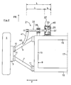
- Fig. 1 is roughly schematically shown a front suspension for the left front wheel 1 of a motor vehicle.
- the front wheel 1 is rotatably mounted on a wheel carrier 3, which is articulated via a front and a rear wishbone 5, 7 on the body side to an auxiliary frame 9.
- the wishbones 5, 7 are each about pivot bearing 11 wheel side and attached on the body side.
- the subframe 9 has two lateral side members 13 and two cross members 15 and is fastened in a manner not shown on the structure of the motor vehicle.
- the in the Fig. 1 shown arrangement is shown only to the vehicle center 17 level.
- the right, not shown here side of the suspension is executed in mirror image.
- Other components of the suspension such as upper wishbones. Shock absorber or suspension spring are not shown for reasons of clarity. Likewise components are omitted which relate to the steering of the front wheels 1.
- a two-piece executed stabilizer 19 is arranged on the front cross member 15 of the subframe 9, of which in the Fig. 1 only the left stabilizer part 21 is shown.
- the stabilizer part 21 is adjustable in terms of its effect on the front transverse link 5 by means of a motor / gear unit 23. This is composed of an electric motor 25 and a reduction gear 27.
- the reduction gear 27 and the electric motor 25 are according to the Fig. 1 arranged in a common housing which is fastened via a bearing bracket 29 on the subframe 9.
- the electric motor 25 and the reduction gear 27 are aligned coaxially with a torsion bar 31 of the stabilizer part 21.
- the torsion bar 31 is designed as a solid rod whose effective spring length is extended by means of a hollow rod 33.
- the two torsion bars 31, 33 are made of spring steel and accordingly twistable.
- the hollow rod 33 is connected to its transmission-side end 37 drivingly connected to the output of the reduction gear 27 and extends through the electric motor 25 through to close to the vehicle center plane 17th
- the solid rod 31 At its transmission far end of the hollow rod 33 is rotatably connected via a spline to the solid rod 31.
- the solid rod 31 now runs in the direction of the vehicle outer side coaxially through the hollow rod 33 and by the electric motor 25 and the reduction gear 27.
- the solid rod 31 is further guided in the vehicle transverse direction y by a bearing 39 attached to the subframe 9 and has an output lever 41 attached thereto on the vehicle side.
- the output lever 41 is articulated via a pivot point 43 with coupling rod on the lower arm 5.
- Fig. 2 a further serial arrangement of the motor / gear unit 23 and the torsion bar 31 is shown.
- the effective spring length is formed only by a single torsion bar 31.
- the torsion bar 31 carries at its gear-side end 37 a ring gear 45 which is drivingly connected to the reduction gear 27.
- At its transmission far end of the solid rod 31 is also non-rotatably connected to the output lever 41 in connection, which is hinged on the pivot point 43 on the lower arm 5.
- the total length I g of the stabilizer part 21 is therefore essentially composed of an effective spring length I F and an axial length I A of the motor / gear unit 23.
- the motor / gear unit 23 is arranged axially parallel to the torsion bar 31.
- the motor / gear unit 23 is upstream of the associated torsion bar 31 in the vehicle longitudinal direction x and attached via a bearing bracket 29 on the subframe 9.
- the torsion bar 31 therefore extends between the motor / gear unit 23 and the front cross member 15 of the subframe 9 laterally outward.
- the reduction gear 27 of the engine-transmission unit is according to the Fig. 3a not directly drivingly connected to the torsion bar 31 in connection, but via an additional spur gear 47.
- the spur gear 47 takes place in the load path, a force deflection by 180 ° on the torsion bar 31, which is guided to the vehicle side.
- the spur gear 47 is disposed outside the housing of the motor / gear unit 23 and has an output gear 49 which is supported by an output shaft 51 of the reduction gear 27.
- the driven gear 49 is engaged with a fixed gear 53 carried by the torsion bar 31.
- the stabilizer member 21 is therefore in contrast to the Fig. 1 and 2 in the vehicle transverse direction y extended by the length I A of the engine / transmission unit 23.
- a gear portion 55 is formed on the torsion bar 31, which meshes with the output gear 49 of the reduction gear 27.
- the gear portion 55 is designed so that an adjustment of the torsion bar 31 by a few degrees is readily feasible.
- a dash-dotted line indicates a radius within which the motor / gear unit 23 can be arranged around the torsion bar 31 around. The angular position of the motor / gear unit 23 depends on the respective space requirements.
- a stabilizer part 21 is shown, which is provided in contrast to the preceding figures in the vehicle longitudinal direction x behind the subframe 9. Accordingly, the motor / gear unit 23 is attached via the bearing bracket 29 to the rear cross member 15 of the subframe 9. The output lever 41 is articulated via the pivot point 43 on the rear lower arm 7.
- the stabilizer part 21 In contrast to the previous embodiments extends in the Fig. 5 the stabilizer part 21 with its torsion bar 31 in the vehicle longitudinal direction x.
- the stabilizer part 21 is fastened in the vehicle longitudinal direction behind the subframe 9, while the two motor / gear units 23 are arranged facing each other in the respective inner sides of the torsion bars 31.
- the torsion bar 31 is according to the Fig. 5 arranged axially parallel to a pivot axis 49 of the pivot bearing 11, whereby the steering behavior of the suspension is favored as a whole.
- the pivot axis 49 can also be aligned coaxially with the torsion bar 31.
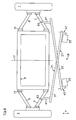
- the two stabilizer parts 21 are arranged in the vehicle longitudinal direction x behind the subframe 9.
- the torsion bars 31 of the two stabilizer parts 21 cross each other approximately in the vehicle center plane 17.
- Both torsion bars 31 are in accordance with the Fig. 6 inclined at the same oblique angle starting from the respective output levers 41 to the vehicle center backwards.
- the torsion bars 31 are elongated so that with respect to the vehicle central axis 17 of the respective output lever 41 and the thus engine connected engine / transmission unit 23 are each on opposite sides of the vehicle.
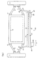
- a further embodiment is shown, in which the stabilizer parts 19, as in the Fig. 6 , also extend over almost the entire vehicle width in the transverse direction y.
- the two torsion bars 31 are aligned axially parallel to each other in the vehicle transverse direction y and spaced from each other by a slight gap distance.
- the two motor / gear units 23 are in different angular positions with the associated torsion bars 31 coupled to achieve a total compact arrangement of the stabilizer.
Landscapes
- Engineering & Computer Science (AREA)
- Mechanical Engineering (AREA)
- Vehicle Body Suspensions (AREA)
Applications Claiming Priority (1)
| Application Number | Priority Date | Filing Date | Title |
|---|---|---|---|
| DE102009052877A DE102009052877A1 (de) | 2009-11-13 | 2009-11-13 | Anordnung eines zweiteilig ausgeführten Stabilisators an einer Radeaufhängung für ein Kraftfahrzeug |
Publications (3)
| Publication Number | Publication Date |
|---|---|
| EP2322366A2 true EP2322366A2 (fr) | 2011-05-18 |
| EP2322366A3 EP2322366A3 (fr) | 2012-05-16 |
| EP2322366B1 EP2322366B1 (fr) | 2014-03-26 |
Family
ID=43450274
Family Applications (1)
| Application Number | Title | Priority Date | Filing Date |
|---|---|---|---|
| EP20100013906 Not-in-force EP2322366B1 (fr) | 2009-11-13 | 2010-10-23 | Agencement d'un stabilisateur constitué de deux parties sur une suspension de roue pour un véhicule automobile |
Country Status (2)
| Country | Link |
|---|---|
| EP (1) | EP2322366B1 (fr) |
| DE (1) | DE102009052877A1 (fr) |
Cited By (4)
| Publication number | Priority date | Publication date | Assignee | Title |
|---|---|---|---|---|
| WO2012016610A1 (fr) * | 2010-07-31 | 2012-02-09 | Audi Ag | Dispositif de réglage d'essieu d'un véhicule automobile |
| CN102848874A (zh) * | 2011-07-01 | 2013-01-02 | 奥迪股份公司 | 用于机动车轮悬架结构的调整装置 |
| EP2767421A1 (fr) * | 2013-02-16 | 2014-08-20 | Audi Ag | Système de ressort à barre de torsion pour la suspension d'un roue d' un véhicule automobile |
| CN105813867A (zh) * | 2013-12-09 | 2016-07-27 | 奥迪股份公司 | 用于机动车的车桥的车轮的能够主动地调节的车轮悬架 |
Families Citing this family (17)
| Publication number | Priority date | Publication date | Assignee | Title |
|---|---|---|---|---|
| DE102011115222A1 (de) * | 2011-09-24 | 2013-03-28 | Audi Ag | Stabilisatoranordnung für eine Radaufhängung von Kraftfahrzeugen |
| DE102011121327B4 (de) | 2011-12-16 | 2019-04-11 | Audi Ag | Stellvorrichtung für ein Kraftfahrzeug |
| DE102012218396A1 (de) | 2012-10-10 | 2014-04-24 | Zf Friedrichshafen Ag | Stabilisator für ein Fahrwerk eines Kraftfahrzeugs |
| DE102013002710A1 (de) | 2013-02-16 | 2014-08-21 | Audi Ag | Radaufhängung für ein Kraftfahrzeug |
| DE102013002703B4 (de) | 2013-02-16 | 2024-10-02 | Audi Ag | Drehfedersystem für eine Fahrzeugachse |
| DE102013007355A1 (de) | 2013-04-27 | 2014-10-30 | Audi Ag | Radaufhängung für ein Kraftfahrzeug |
| DE102013010657B4 (de) | 2013-06-26 | 2016-09-01 | Audi Ag | Stellvorrichtung für eine Radaufhängung eines Kraftfahrzeugs |
| DE102013012755A1 (de) | 2013-07-31 | 2015-02-05 | Audi Ag | Drehfederstabsystem für eine Radaufhängung eines Kraftfahrzeugs |
| DE102013021344A1 (de) | 2013-12-14 | 2015-06-18 | Audi Ag | Anbindung eines Frontends eines Kraftfahrzeugs an einen Hilfsrahmen des Kraftfahrzeugs |
| DE102014118101A1 (de) | 2014-12-08 | 2016-06-09 | Ovalo Gmbh | Aktive Stabilisatorvorrichtung für ein Fahrzeug |
| DE102015103328A1 (de) * | 2015-03-06 | 2016-09-08 | Ovalo Gmbh | Fahrzeug mit einer aktiven Stabilisatorvorrichtung |
| DE102018104885A1 (de) | 2017-11-15 | 2019-01-24 | Schaeffler Technologies AG & Co. KG | Drehstabfeder und aktiver Wankstabilisator |
| DE102018104883A1 (de) | 2017-11-16 | 2019-01-31 | Schaeffler Technologies AG & Co. KG | Aktiver Wankstabilisator und Verfahren zur Stabilisierung eines Fahrzeugs |
| DE102018107427A1 (de) | 2017-12-11 | 2019-06-13 | Schaeffler Technologies AG & Co. KG | Wankstabilisator für ein Kraftfahrzeug |
| US11279195B2 (en) | 2019-07-30 | 2022-03-22 | Honda Motor Co., Ltd. | Individual active torsional springs |
| FR3120331A1 (fr) * | 2021-03-02 | 2022-09-09 | Renault S.A.S | Système suspension active avec mécanisme planétaire différentiel |
| DE102023132500A1 (de) * | 2023-11-22 | 2025-05-22 | Ford Global Technologies Llc | Aktivfedereinheit |
Citations (1)
| Publication number | Priority date | Publication date | Assignee | Title |
|---|---|---|---|---|
| DE102007007214A1 (de) | 2007-02-14 | 2008-08-21 | Volkswagen Ag | Anordnung eines Stabilisators an einer Radaufhängung für Kraftfahrzeuge |
Family Cites Families (8)
| Publication number | Priority date | Publication date | Assignee | Title |
|---|---|---|---|---|
| DE3928062A1 (de) * | 1989-08-25 | 1990-11-29 | Daimler Benz Ag | Vorrichtung zur beeinflussung der lage eines kraftfahrzeugaufbaues zu einer fahrzeugachse |
| US5288101A (en) * | 1992-05-28 | 1994-02-22 | Minnett Milford M | Variable rate torsion control system for vehicle suspension |
| DE10242552B4 (de) * | 2002-09-13 | 2004-09-16 | Audi Ag | Vorrichtung zum elektromechanischen Verstellen |
| DE102004004335B4 (de) * | 2004-01-29 | 2017-07-13 | Zf Friedrichshafen Ag | Fahrwerksanordnung für ein Fahrzeug |
| JP4244999B2 (ja) * | 2006-02-09 | 2009-03-25 | トヨタ自動車株式会社 | 車両用スタビライザシステム |
| DE102008010131A1 (de) * | 2007-04-21 | 2008-10-23 | Schaeffler Kg | Wankstabilisator für ein Kraftfahrzeug sowie Gehäuse für den Wankstabilisator |
| DE102007024770A1 (de) * | 2007-05-26 | 2008-11-27 | Bayerische Motoren Werke Aktiengesellschaft | Aktives Fahrwerk für Kraftfahrzeuge |
| DE102008009874A1 (de) * | 2008-02-19 | 2009-08-20 | Bayerische Motoren Werke Aktiengesellschaft | Anordnung eines Wankstabilisierungssystems sowie eines Lenksystems an einem Kraftfahrzeug |
-
2009
- 2009-11-13 DE DE102009052877A patent/DE102009052877A1/de not_active Withdrawn
-
2010
- 2010-10-23 EP EP20100013906 patent/EP2322366B1/fr not_active Not-in-force
Patent Citations (1)
| Publication number | Priority date | Publication date | Assignee | Title |
|---|---|---|---|---|
| DE102007007214A1 (de) | 2007-02-14 | 2008-08-21 | Volkswagen Ag | Anordnung eines Stabilisators an einer Radaufhängung für Kraftfahrzeuge |
Cited By (8)
| Publication number | Priority date | Publication date | Assignee | Title |
|---|---|---|---|---|
| WO2012016610A1 (fr) * | 2010-07-31 | 2012-02-09 | Audi Ag | Dispositif de réglage d'essieu d'un véhicule automobile |
| US8827287B2 (en) | 2010-07-31 | 2014-09-09 | Audi Ag | Axle control element of a motor vehicle |
| CN102848874A (zh) * | 2011-07-01 | 2013-01-02 | 奥迪股份公司 | 用于机动车轮悬架结构的调整装置 |
| CN102848874B (zh) * | 2011-07-01 | 2015-04-15 | 奥迪股份公司 | 用于机动车轮悬架结构的调整装置 |
| EP2767421A1 (fr) * | 2013-02-16 | 2014-08-20 | Audi Ag | Système de ressort à barre de torsion pour la suspension d'un roue d' un véhicule automobile |
| US9108482B2 (en) | 2013-02-16 | 2015-08-18 | Audi Ag | Torsion bar spring arrangement for a wheel suspension of a motor vehicle |
| CN105813867A (zh) * | 2013-12-09 | 2016-07-27 | 奥迪股份公司 | 用于机动车的车桥的车轮的能够主动地调节的车轮悬架 |
| CN105813867B (zh) * | 2013-12-09 | 2018-04-06 | 奥迪股份公司 | 用于机动车的车桥的车轮的能够主动地调节的车轮悬架 |
Also Published As
| Publication number | Publication date |
|---|---|
| DE102009052877A1 (de) | 2011-05-19 |
| EP2322366B1 (fr) | 2014-03-26 |
| EP2322366A3 (fr) | 2012-05-16 |
| DE102009052877A8 (de) | 2011-08-18 |
Similar Documents
| Publication | Publication Date | Title |
|---|---|---|
| EP2322366B1 (fr) | Agencement d'un stabilisateur constitué de deux parties sur une suspension de roue pour un véhicule automobile | |
| EP2389298B1 (fr) | Dispositif de stabilisateur sur une suspension de roue de véhicule motorisé | |
| EP2389300B1 (fr) | Dispositif de stabilisateur sur une suspension de roue de véhicule motorisé | |
| EP2517905B1 (fr) | Agencement de ressort pour suspensions de roues de véhicules automobiles | |
| EP1958804B1 (fr) | Agencement d'un stabilisateur sur la suspension de roue de véhicules automobiles | |
| EP2767421B1 (fr) | Système de ressort à barre de torsion pour la suspension d'un roue d' un véhicule automobile | |
| EP2598349B1 (fr) | Dispositif de réglage d'essieu d'un véhicule automobile | |
| EP2285606B1 (fr) | Barre anti-roulis pour véhicule utilitaire | |
| EP2282900B1 (fr) | Essieu arrière de véhicule motorisé à sens de braquage opposé au sens de braquage de l'essieu avant | |
| DE102012005395B4 (de) | Federungsanordnung für eine Radaufhängung eines Kraftfahrzeuges | |
| EP2956315B1 (fr) | Suspension de roue conçue pour un véhicule automobile | |
| EP2291293B1 (fr) | Essieu arrière de véhicule à contre-braquage | |
| EP3027439B1 (fr) | Système à barre de torsion pour une suspension d'un vehicule | |
| EP2755833A1 (fr) | Essieu arrière à traverse de torsion, dirigeable | |
| EP1882600B1 (fr) | Essieu à traverse déformable en torsion | |
| DE102021213066B4 (de) | Lenkachse für ein lenkbares Fahrzeug und Flurförderzeug | |
| EP1754649A1 (fr) | Dispositif pour modifier le carrossage ou le pincement des roues du véhicule | |
| DE102015103354B4 (de) | Aktive Stabilisatorvorrichtung für ein Fahrzeug | |
| EP3649038B1 (fr) | Dispositif de réglage pour un châssis de véhicule à moteur, et direction d'essieu arrière | |
| DE102020113865A1 (de) | Radaufhängung | |
| WO2023160970A1 (fr) | Suspension de roue pour roue de véhicule | |
| DE102013002703B4 (de) | Drehfedersystem für eine Fahrzeugachse | |
| EP3409516B1 (fr) | Châssis actif | |
| EP3556583A1 (fr) | Procédé de fabrication de cadres d'essieu | |
| DE102018109281A1 (de) | Verfahren zum Herstellen von Fahrschemeln |
Legal Events
| Date | Code | Title | Description |
|---|---|---|---|
| PUAI | Public reference made under article 153(3) epc to a published international application that has entered the european phase |
Free format text: ORIGINAL CODE: 0009012 |
|
| AK | Designated contracting states |
Kind code of ref document: A2 Designated state(s): AL AT BE BG CH CY CZ DE DK EE ES FI FR GB GR HR HU IE IS IT LI LT LU LV MC MK MT NL NO PL PT RO RS SE SI SK SM TR |
|
| AX | Request for extension of the european patent |
Extension state: BA ME |
|
| PUAL | Search report despatched |
Free format text: ORIGINAL CODE: 0009013 |
|
| AK | Designated contracting states |
Kind code of ref document: A3 Designated state(s): AL AT BE BG CH CY CZ DE DK EE ES FI FR GB GR HR HU IE IS IT LI LT LU LV MC MK MT NL NO PL PT RO RS SE SI SK SM TR |
|
| AX | Request for extension of the european patent |
Extension state: BA ME |
|
| RIC1 | Information provided on ipc code assigned before grant |
Ipc: B60G 21/055 20060101AFI20120410BHEP |
|
| 17P | Request for examination filed |
Effective date: 20121116 |
|
| 17Q | First examination report despatched |
Effective date: 20130215 |
|
| GRAP | Despatch of communication of intention to grant a patent |
Free format text: ORIGINAL CODE: EPIDOSNIGR1 |
|
| INTG | Intention to grant announced |
Effective date: 20140122 |
|
| GRAS | Grant fee paid |
Free format text: ORIGINAL CODE: EPIDOSNIGR3 |
|
| GRAA | (expected) grant |
Free format text: ORIGINAL CODE: 0009210 |
|
| AK | Designated contracting states |
Kind code of ref document: B1 Designated state(s): AL AT BE BG CH CY CZ DE DK EE ES FI FR GB GR HR HU IE IS IT LI LT LU LV MC MK MT NL NO PL PT RO RS SE SI SK SM TR |
|
| REG | Reference to a national code |
Ref country code: GB Ref legal event code: FG4D Free format text: NOT ENGLISH |
|
| REG | Reference to a national code |
Ref country code: CH Ref legal event code: EP |
|
| REG | Reference to a national code |
Ref country code: AT Ref legal event code: REF Ref document number: 658776 Country of ref document: AT Kind code of ref document: T Effective date: 20140415 |
|
| REG | Reference to a national code |
Ref country code: IE Ref legal event code: FG4D Free format text: LANGUAGE OF EP DOCUMENT: GERMAN |
|
| REG | Reference to a national code |
Ref country code: DE Ref legal event code: R096 Ref document number: 502010006457 Country of ref document: DE Effective date: 20140508 |
|
| PG25 | Lapsed in a contracting state [announced via postgrant information from national office to epo] |
Ref country code: LT Free format text: LAPSE BECAUSE OF FAILURE TO SUBMIT A TRANSLATION OF THE DESCRIPTION OR TO PAY THE FEE WITHIN THE PRESCRIBED TIME-LIMIT Effective date: 20140326 Ref country code: NO Free format text: LAPSE BECAUSE OF FAILURE TO SUBMIT A TRANSLATION OF THE DESCRIPTION OR TO PAY THE FEE WITHIN THE PRESCRIBED TIME-LIMIT Effective date: 20140626 |
|
| REG | Reference to a national code |
Ref country code: NL Ref legal event code: VDEP Effective date: 20140326 |
|
| REG | Reference to a national code |
Ref country code: LT Ref legal event code: MG4D |
|
| PG25 | Lapsed in a contracting state [announced via postgrant information from national office to epo] |
Ref country code: FI Free format text: LAPSE BECAUSE OF FAILURE TO SUBMIT A TRANSLATION OF THE DESCRIPTION OR TO PAY THE FEE WITHIN THE PRESCRIBED TIME-LIMIT Effective date: 20140326 Ref country code: SE Free format text: LAPSE BECAUSE OF FAILURE TO SUBMIT A TRANSLATION OF THE DESCRIPTION OR TO PAY THE FEE WITHIN THE PRESCRIBED TIME-LIMIT Effective date: 20140326 |
|
| PG25 | Lapsed in a contracting state [announced via postgrant information from national office to epo] |
Ref country code: RS Free format text: LAPSE BECAUSE OF FAILURE TO SUBMIT A TRANSLATION OF THE DESCRIPTION OR TO PAY THE FEE WITHIN THE PRESCRIBED TIME-LIMIT Effective date: 20140326 Ref country code: LV Free format text: LAPSE BECAUSE OF FAILURE TO SUBMIT A TRANSLATION OF THE DESCRIPTION OR TO PAY THE FEE WITHIN THE PRESCRIBED TIME-LIMIT Effective date: 20140326 Ref country code: HR Free format text: LAPSE BECAUSE OF FAILURE TO SUBMIT A TRANSLATION OF THE DESCRIPTION OR TO PAY THE FEE WITHIN THE PRESCRIBED TIME-LIMIT Effective date: 20140326 |
|
| PG25 | Lapsed in a contracting state [announced via postgrant information from national office to epo] |
Ref country code: CZ Free format text: LAPSE BECAUSE OF FAILURE TO SUBMIT A TRANSLATION OF THE DESCRIPTION OR TO PAY THE FEE WITHIN THE PRESCRIBED TIME-LIMIT Effective date: 20140326 Ref country code: BG Free format text: LAPSE BECAUSE OF FAILURE TO SUBMIT A TRANSLATION OF THE DESCRIPTION OR TO PAY THE FEE WITHIN THE PRESCRIBED TIME-LIMIT Effective date: 20140626 Ref country code: CY Free format text: LAPSE BECAUSE OF FAILURE TO SUBMIT A TRANSLATION OF THE DESCRIPTION OR TO PAY THE FEE WITHIN THE PRESCRIBED TIME-LIMIT Effective date: 20140326 Ref country code: RO Free format text: LAPSE BECAUSE OF FAILURE TO SUBMIT A TRANSLATION OF THE DESCRIPTION OR TO PAY THE FEE WITHIN THE PRESCRIBED TIME-LIMIT Effective date: 20140326 Ref country code: EE Free format text: LAPSE BECAUSE OF FAILURE TO SUBMIT A TRANSLATION OF THE DESCRIPTION OR TO PAY THE FEE WITHIN THE PRESCRIBED TIME-LIMIT Effective date: 20140326 Ref country code: NL Free format text: LAPSE BECAUSE OF FAILURE TO SUBMIT A TRANSLATION OF THE DESCRIPTION OR TO PAY THE FEE WITHIN THE PRESCRIBED TIME-LIMIT Effective date: 20140326 Ref country code: IS Free format text: LAPSE BECAUSE OF FAILURE TO SUBMIT A TRANSLATION OF THE DESCRIPTION OR TO PAY THE FEE WITHIN THE PRESCRIBED TIME-LIMIT Effective date: 20140726 |
|
| PG25 | Lapsed in a contracting state [announced via postgrant information from national office to epo] |
Ref country code: PL Free format text: LAPSE BECAUSE OF FAILURE TO SUBMIT A TRANSLATION OF THE DESCRIPTION OR TO PAY THE FEE WITHIN THE PRESCRIBED TIME-LIMIT Effective date: 20140326 Ref country code: ES Free format text: LAPSE BECAUSE OF FAILURE TO SUBMIT A TRANSLATION OF THE DESCRIPTION OR TO PAY THE FEE WITHIN THE PRESCRIBED TIME-LIMIT Effective date: 20140326 Ref country code: SK Free format text: LAPSE BECAUSE OF FAILURE TO SUBMIT A TRANSLATION OF THE DESCRIPTION OR TO PAY THE FEE WITHIN THE PRESCRIBED TIME-LIMIT Effective date: 20140326 |
|
| PG25 | Lapsed in a contracting state [announced via postgrant information from national office to epo] |
Ref country code: PT Free format text: LAPSE BECAUSE OF FAILURE TO SUBMIT A TRANSLATION OF THE DESCRIPTION OR TO PAY THE FEE WITHIN THE PRESCRIBED TIME-LIMIT Effective date: 20140728 |
|
| REG | Reference to a national code |
Ref country code: DE Ref legal event code: R097 Ref document number: 502010006457 Country of ref document: DE |
|
| PG25 | Lapsed in a contracting state [announced via postgrant information from national office to epo] |
Ref country code: DK Free format text: LAPSE BECAUSE OF FAILURE TO SUBMIT A TRANSLATION OF THE DESCRIPTION OR TO PAY THE FEE WITHIN THE PRESCRIBED TIME-LIMIT Effective date: 20140326 |
|
| PLBE | No opposition filed within time limit |
Free format text: ORIGINAL CODE: 0009261 |
|
| STAA | Information on the status of an ep patent application or granted ep patent |
Free format text: STATUS: NO OPPOSITION FILED WITHIN TIME LIMIT |
|
| 26N | No opposition filed |
Effective date: 20150106 |
|
| REG | Reference to a national code |
Ref country code: DE Ref legal event code: R097 Ref document number: 502010006457 Country of ref document: DE Effective date: 20150106 |
|
| PG25 | Lapsed in a contracting state [announced via postgrant information from national office to epo] |
Ref country code: MC Free format text: LAPSE BECAUSE OF FAILURE TO SUBMIT A TRANSLATION OF THE DESCRIPTION OR TO PAY THE FEE WITHIN THE PRESCRIBED TIME-LIMIT Effective date: 20140326 Ref country code: LU Free format text: LAPSE BECAUSE OF FAILURE TO SUBMIT A TRANSLATION OF THE DESCRIPTION OR TO PAY THE FEE WITHIN THE PRESCRIBED TIME-LIMIT Effective date: 20141023 |
|
| REG | Reference to a national code |
Ref country code: CH Ref legal event code: PL |
|
| PG25 | Lapsed in a contracting state [announced via postgrant information from national office to epo] |
Ref country code: BE Free format text: LAPSE BECAUSE OF NON-PAYMENT OF DUE FEES Effective date: 20141031 |
|
| REG | Reference to a national code |
Ref country code: IE Ref legal event code: MM4A |
|
| PG25 | Lapsed in a contracting state [announced via postgrant information from national office to epo] |
Ref country code: LI Free format text: LAPSE BECAUSE OF NON-PAYMENT OF DUE FEES Effective date: 20141031 Ref country code: SI Free format text: LAPSE BECAUSE OF FAILURE TO SUBMIT A TRANSLATION OF THE DESCRIPTION OR TO PAY THE FEE WITHIN THE PRESCRIBED TIME-LIMIT Effective date: 20140326 Ref country code: CH Free format text: LAPSE BECAUSE OF NON-PAYMENT OF DUE FEES Effective date: 20141031 |
|
| REG | Reference to a national code |
Ref country code: FR Ref legal event code: PLFP Year of fee payment: 6 |
|
| PG25 | Lapsed in a contracting state [announced via postgrant information from national office to epo] |
Ref country code: IE Free format text: LAPSE BECAUSE OF NON-PAYMENT OF DUE FEES Effective date: 20141023 |
|
| PG25 | Lapsed in a contracting state [announced via postgrant information from national office to epo] |
Ref country code: SM Free format text: LAPSE BECAUSE OF FAILURE TO SUBMIT A TRANSLATION OF THE DESCRIPTION OR TO PAY THE FEE WITHIN THE PRESCRIBED TIME-LIMIT Effective date: 20140326 |
|
| PG25 | Lapsed in a contracting state [announced via postgrant information from national office to epo] |
Ref country code: GR Free format text: LAPSE BECAUSE OF FAILURE TO SUBMIT A TRANSLATION OF THE DESCRIPTION OR TO PAY THE FEE WITHIN THE PRESCRIBED TIME-LIMIT Effective date: 20140627 |
|
| PG25 | Lapsed in a contracting state [announced via postgrant information from national office to epo] |
Ref country code: MT Free format text: LAPSE BECAUSE OF FAILURE TO SUBMIT A TRANSLATION OF THE DESCRIPTION OR TO PAY THE FEE WITHIN THE PRESCRIBED TIME-LIMIT Effective date: 20140326 Ref country code: HU Free format text: LAPSE BECAUSE OF FAILURE TO SUBMIT A TRANSLATION OF THE DESCRIPTION OR TO PAY THE FEE WITHIN THE PRESCRIBED TIME-LIMIT; INVALID AB INITIO Effective date: 20101023 Ref country code: TR Free format text: LAPSE BECAUSE OF FAILURE TO SUBMIT A TRANSLATION OF THE DESCRIPTION OR TO PAY THE FEE WITHIN THE PRESCRIBED TIME-LIMIT Effective date: 20140326 |
|
| REG | Reference to a national code |
Ref country code: FR Ref legal event code: PLFP Year of fee payment: 7 |
|
| REG | Reference to a national code |
Ref country code: AT Ref legal event code: MM01 Ref document number: 658776 Country of ref document: AT Kind code of ref document: T Effective date: 20151023 |
|
| PG25 | Lapsed in a contracting state [announced via postgrant information from national office to epo] |
Ref country code: AT Free format text: LAPSE BECAUSE OF NON-PAYMENT OF DUE FEES Effective date: 20151023 |
|
| REG | Reference to a national code |
Ref country code: FR Ref legal event code: PLFP Year of fee payment: 8 |
|
| PG25 | Lapsed in a contracting state [announced via postgrant information from national office to epo] |
Ref country code: MK Free format text: LAPSE BECAUSE OF FAILURE TO SUBMIT A TRANSLATION OF THE DESCRIPTION OR TO PAY THE FEE WITHIN THE PRESCRIBED TIME-LIMIT Effective date: 20140326 |
|
| REG | Reference to a national code |
Ref country code: FR Ref legal event code: PLFP Year of fee payment: 9 |
|
| PG25 | Lapsed in a contracting state [announced via postgrant information from national office to epo] |
Ref country code: AL Free format text: LAPSE BECAUSE OF FAILURE TO SUBMIT A TRANSLATION OF THE DESCRIPTION OR TO PAY THE FEE WITHIN THE PRESCRIBED TIME-LIMIT Effective date: 20140326 |
|
| PGFP | Annual fee paid to national office [announced via postgrant information from national office to epo] |
Ref country code: DE Payment date: 20211031 Year of fee payment: 12 Ref country code: GB Payment date: 20211023 Year of fee payment: 12 |
|
| PGFP | Annual fee paid to national office [announced via postgrant information from national office to epo] |
Ref country code: IT Payment date: 20211029 Year of fee payment: 12 Ref country code: FR Payment date: 20211023 Year of fee payment: 12 |
|
| REG | Reference to a national code |
Ref country code: DE Ref legal event code: R119 Ref document number: 502010006457 Country of ref document: DE |
|
| GBPC | Gb: european patent ceased through non-payment of renewal fee |
Effective date: 20221023 |
|
| P01 | Opt-out of the competence of the unified patent court (upc) registered |
Effective date: 20230530 |
|
| PG25 | Lapsed in a contracting state [announced via postgrant information from national office to epo] |
Ref country code: FR Free format text: LAPSE BECAUSE OF NON-PAYMENT OF DUE FEES Effective date: 20221031 Ref country code: DE Free format text: LAPSE BECAUSE OF NON-PAYMENT OF DUE FEES Effective date: 20230503 |
|
| PG25 | Lapsed in a contracting state [announced via postgrant information from national office to epo] |
Ref country code: IT Free format text: LAPSE BECAUSE OF NON-PAYMENT OF DUE FEES Effective date: 20221023 Ref country code: GB Free format text: LAPSE BECAUSE OF NON-PAYMENT OF DUE FEES Effective date: 20221023 |