EP2322708A2 - Appareil ménager doté d'un échangeur thermique en matière synthétique thermoplastique, et un tel échangeur thermique - Google Patents
Appareil ménager doté d'un échangeur thermique en matière synthétique thermoplastique, et un tel échangeur thermique Download PDFInfo
- Publication number
- EP2322708A2 EP2322708A2 EP10190071A EP10190071A EP2322708A2 EP 2322708 A2 EP2322708 A2 EP 2322708A2 EP 10190071 A EP10190071 A EP 10190071A EP 10190071 A EP10190071 A EP 10190071A EP 2322708 A2 EP2322708 A2 EP 2322708A2
- Authority
- EP
- European Patent Office
- Prior art keywords
- heat exchanger
- process air
- domestic appliance
- carbon nanotubes
- composite material
- Prior art date
- Legal status (The legal status is an assumption and is not a legal conclusion. Google has not performed a legal analysis and makes no representation as to the accuracy of the status listed.)
- Withdrawn
Links
- 229920001169 thermoplastic Polymers 0.000 title claims abstract description 15
- 239000000463 material Substances 0.000 title claims abstract description 11
- 239000004416 thermosoftening plastic Substances 0.000 title claims description 10
- 239000002041 carbon nanotube Substances 0.000 claims abstract description 37
- 239000002131 composite material Substances 0.000 claims abstract description 37
- 238000000034 method Methods 0.000 claims abstract description 37
- OKTJSMMVPCPJKN-UHFFFAOYSA-N Carbon Chemical compound [C] OKTJSMMVPCPJKN-UHFFFAOYSA-N 0.000 claims abstract description 27
- 229910021393 carbon nanotube Inorganic materials 0.000 claims abstract description 26
- 238000001035 drying Methods 0.000 claims abstract description 16
- 238000009833 condensation Methods 0.000 claims abstract description 10
- 230000005494 condensation Effects 0.000 claims abstract description 10
- 239000004033 plastic Substances 0.000 claims abstract description 9
- 229920003023 plastic Polymers 0.000 claims abstract description 9
- 239000004020 conductor Substances 0.000 claims abstract description 8
- 238000001816 cooling Methods 0.000 claims abstract description 7
- 239000002270 dispersing agent Substances 0.000 claims abstract description 7
- 239000004743 Polypropylene Substances 0.000 claims abstract description 6
- -1 polypropylene Polymers 0.000 claims abstract description 6
- 229920001155 polypropylene Polymers 0.000 claims abstract description 6
- 229920001577 copolymer Polymers 0.000 claims abstract description 5
- 238000010438 heat treatment Methods 0.000 claims abstract description 5
- PPBRXRYQALVLMV-UHFFFAOYSA-N Styrene Natural products C=CC1=CC=CC=C1 PPBRXRYQALVLMV-UHFFFAOYSA-N 0.000 claims abstract description 4
- 229920000098 polyolefin Polymers 0.000 claims abstract description 4
- 229920000089 Cyclic olefin copolymer Polymers 0.000 claims abstract description 3
- 238000003421 catalytic decomposition reaction Methods 0.000 claims abstract description 3
- 229930195733 hydrocarbon Natural products 0.000 claims abstract description 3
- 150000002430 hydrocarbons Chemical group 0.000 claims abstract description 3
- 230000008021 deposition Effects 0.000 claims abstract 2
- 239000012808 vapor phase Substances 0.000 claims abstract 2
- 239000012815 thermoplastic material Substances 0.000 claims description 13
- XECAHXYUAAWDEL-UHFFFAOYSA-N acrylonitrile butadiene styrene Chemical compound C=CC=C.C=CC#N.C=CC1=CC=CC=C1 XECAHXYUAAWDEL-UHFFFAOYSA-N 0.000 claims description 4
- 229920000122 acrylonitrile butadiene styrene Polymers 0.000 claims description 4
- 239000004676 acrylonitrile butadiene styrene Substances 0.000 claims description 4
- 238000004519 manufacturing process Methods 0.000 abstract description 5
- 238000004140 cleaning Methods 0.000 description 4
- 229910052751 metal Inorganic materials 0.000 description 4
- 239000002184 metal Substances 0.000 description 4
- 229910052782 aluminium Inorganic materials 0.000 description 3
- XAGFODPZIPBFFR-UHFFFAOYSA-N aluminium Chemical compound [Al] XAGFODPZIPBFFR-UHFFFAOYSA-N 0.000 description 3
- 239000000654 additive Substances 0.000 description 2
- 238000011049 filling Methods 0.000 description 2
- 239000000155 melt Substances 0.000 description 2
- 238000002156 mixing Methods 0.000 description 2
- 238000005406 washing Methods 0.000 description 2
- XLYOFNOQVPJJNP-UHFFFAOYSA-N water Substances O XLYOFNOQVPJJNP-UHFFFAOYSA-N 0.000 description 2
- RYGMFSIKBFXOCR-UHFFFAOYSA-N Copper Chemical compound [Cu] RYGMFSIKBFXOCR-UHFFFAOYSA-N 0.000 description 1
- 125000004432 carbon atom Chemical group C* 0.000 description 1
- 229910052802 copper Inorganic materials 0.000 description 1
- 239000010949 copper Substances 0.000 description 1
- 230000001419 dependent effect Effects 0.000 description 1
- 230000003670 easy-to-clean Effects 0.000 description 1
- 238000010891 electric arc Methods 0.000 description 1
- 239000000945 filler Substances 0.000 description 1
- 238000011010 flushing procedure Methods 0.000 description 1
- 150000002334 glycols Chemical class 0.000 description 1
- 229910002804 graphite Inorganic materials 0.000 description 1
- 239000010439 graphite Substances 0.000 description 1
- 239000007788 liquid Substances 0.000 description 1
- 238000002844 melting Methods 0.000 description 1
- 230000008018 melting Effects 0.000 description 1
- 150000002739 metals Chemical class 0.000 description 1
- VNWKTOKETHGBQD-UHFFFAOYSA-N methane Chemical compound C VNWKTOKETHGBQD-UHFFFAOYSA-N 0.000 description 1
- 229920000642 polymer Polymers 0.000 description 1
- 239000007787 solid Substances 0.000 description 1
- 125000006850 spacer group Chemical group 0.000 description 1
- 238000003856 thermoforming Methods 0.000 description 1
- 238000007740 vapor deposition Methods 0.000 description 1
- 238000009834 vaporization Methods 0.000 description 1
- 230000008016 vaporization Effects 0.000 description 1
Images
Classifications
-
- D—TEXTILES; PAPER
- D06—TREATMENT OF TEXTILES OR THE LIKE; LAUNDERING; FLEXIBLE MATERIALS NOT OTHERWISE PROVIDED FOR
- D06F—LAUNDERING, DRYING, IRONING, PRESSING OR FOLDING TEXTILE ARTICLES
- D06F58/00—Domestic laundry dryers
- D06F58/20—General details of domestic laundry dryers
- D06F58/24—Condensing arrangements
-
- F—MECHANICAL ENGINEERING; LIGHTING; HEATING; WEAPONS; BLASTING
- F28—HEAT EXCHANGE IN GENERAL
- F28F—DETAILS OF HEAT-EXCHANGE AND HEAT-TRANSFER APPARATUS, OF GENERAL APPLICATION
- F28F21/00—Constructions of heat-exchange apparatus characterised by the selection of particular materials
- F28F21/02—Constructions of heat-exchange apparatus characterised by the selection of particular materials of carbon, e.g. graphite
-
- F—MECHANICAL ENGINEERING; LIGHTING; HEATING; WEAPONS; BLASTING
- F28—HEAT EXCHANGE IN GENERAL
- F28F—DETAILS OF HEAT-EXCHANGE AND HEAT-TRANSFER APPARATUS, OF GENERAL APPLICATION
- F28F21/00—Constructions of heat-exchange apparatus characterised by the selection of particular materials
- F28F21/06—Constructions of heat-exchange apparatus characterised by the selection of particular materials of plastics material
-
- F—MECHANICAL ENGINEERING; LIGHTING; HEATING; WEAPONS; BLASTING
- F28—HEAT EXCHANGE IN GENERAL
- F28F—DETAILS OF HEAT-EXCHANGE AND HEAT-TRANSFER APPARATUS, OF GENERAL APPLICATION
- F28F2255/00—Heat exchanger elements made of materials having special features or resulting from particular manufacturing processes
- F28F2255/20—Heat exchanger elements made of materials having special features or resulting from particular manufacturing processes with nanostructures
Definitions
- the invention relates to a domestic appliance, in particular a tumble dryer, with a heat exchanger made of a heat exchanging material containing a thermoplastic material.
- the invention relates to such a domestic appliance in which the heat exchanger of this material has an improved thermal conductivity.
- the invention in this case regards a heat exchanger in which the heat-conducting material is contained in the component through which the heat transfer required for the intended heat exchange takes place, so that the heat exchange takes place through this material.
- This component can be designed, for example, as a tube or hollow plate and combined with many identical components in a single heat exchanger, wherein all these components are held by other components, which is less important in the present case.
- the invention relates in particular to a water-conducting domestic appliance such as a tumble dryer, a washer-dryer or a dishwasher, in which domestic appliance a particular moisture-containing process air stream must be cooled or heated by a heat exchange with another gas stream.
- a tumble dryer (hereinafter also referred to as "dryer” for short) of a type as a condensation dryer, so-called process air is passed through a fan via a heater into a moist drum to be dried containing laundry as a drying chamber.
- the hot air absorbs moisture from the laundry to be dried.
- the now moist process air is directed into a heat exchanger, which is usually preceded by a lint filter.
- this heat exchanger eg air-to-air heat exchanger or heat sink of a heat pump
- the moist process air is cooled, so that the water contained in the moist process air condenses.
- the condensed water (condensate) is then usually collected in a suitable container and the cooled and dried air again fed to the heater and then the drum.
- Another type of tumble dryer is the so-called exhaust air dryer in which the Process air is conducted in an open circuit. The process air is drawn in from an environment of the dryer, heated, passed over the laundry to be dried and released in the simplest case again from the dryer. If no heat exchanger is needed in this simplest case, yet an embodiment of an exhaust air dryer is known in which a heat exchanger for cooling the process air to be discharged from the dryer for the purpose of recovering heat from this process air is used.
- the heat exchanger is generally made of a good heat conducting material, generally of a metal such as e.g. Aluminum or copper.
- a heat exchanger made of a thermoplastic material attempts have already been made to use a heat exchanger made of a thermoplastic material.
- the font DE 199 58 106 B4 describes a cross-flow heat exchanger for a condensation dryer with a plurality of flat heat exchanger plates, which are stacked as a package at a distance and parallel to each other and each by two opposing plate edge portions interconnected and at least one humid air between them enclosing plate members made of a thermoplastic or from a thermally conductive metal existing film are formed, which heat exchanger plates have a plurality of vertically formed from the film, cooling fins forming webs.
- the writings DE 102 18 274 A1 and DE 20 22 1788 U1 describe a heat exchange plate for a cross-flow heat exchanger, which is formed from two spaced-apart, along two opposing edge portions tightly interconnected plate parts.
- the plate parts are formed from thermoplastic or from a thermally conductive metal existing film and define a flow channel for a first, through the cross-flow heat exchanger to be led through medium, for example. Process air.
- heat exchangers with aluminum fins and plates are generally used in conventional heat exchangers.
- heat exchangers made of thermoplastic material Although you could counteract the poor thermal conductivity by the fact that the plate thickness of the heat exchanger is reduced.
- the heat conduction in the rib is very small in heat exchangers made of plastic compared to the heat transfer on the outside of a rib.
- the object of the present invention is therefore to provide a domestic appliance with a heat exchanger constructed with a plastic material, wherein the heat exchanger has improved thermal conduction properties.
- the invention thus relates to a domestic appliance with a heat exchanger, which is constructed with a thermally conductive material which contains a thermoplastic material, wherein the material is a composite material containing the thermoplastic material and carbon nanotubes (CNTs).
- a thermally conductive material which contains a thermoplastic material
- the material is a composite material containing the thermoplastic material and carbon nanotubes (CNTs).
- Carbon nanotubes (CNTs) according to the invention are microscopic tubular structures of many carbon atoms, which occupy a honeycomb structure with hexagons and three bonding partners. Carbon nanotubes generally have a diameter of 0.4 nm to 50 nm and a length of 10 ⁇ m to 10 mm.
- Carbon nanotubes having a diameter of 5 to 15 nm and a length of 1 to 15 ⁇ m are preferably used in the composite material of the present heat exchanger.
- the composite material preferably contains the carbon nanotubes (CNTs) in an amount of 0.1 to 15% by weight and more preferably in an amount of 0.8 to 8% by weight, based in each case on the composite material.
- CNTs carbon nanotubes
- thermoplastic in the composite material is preferably selected from the group consisting of polyolefins, olefin copolymers and styrene copolymers.
- the plastic is a polyolefin which is a polypropylene.
- the plastic is a styrene copolymer and selected from acrylonitrile-butadiene-styrene copolymer (ABS).
- the composite material contains polypropylene as the thermoplastic material.
- the composite material preferably contains only conventional additives in addition to the thermoplastic material and the carbon nanotubes.
- a particular advantage of the present invention is that the amount of fillers can be relatively low.
- the composite preferably contains carbon nanotubes (CNTs) in an amount of from 0.1 to 15% by weight, based on the composite material.
- the composite material particularly preferably contains carbon nanotubes (CNTs) in an amount of 0.8 to 8% by weight, based on the composite material.
- the carbon nanotubes can be single or multiwalled. According to the invention it is preferred that the carbon nanotubes are multiwalled.
- the carbon nanotubes that can be used for the composite can be produced in various ways, for example by vaporization of graphite with a laser or by an arc discharge between carbon electrodes. According to the invention, preference is given to using carbon nanotubes which are obtainable are by vapor deposition in the catalytic decomposition of hydrocarbons (CVD).
- CVD catalytic decomposition of hydrocarbons
- a dispersant is used for a thorough mixing of thermoplastic and carbon nanotubes in the composite material.
- the composite is prepared using a dispersant for the carbon nanotubes in the thermoplastic.
- Suitable dispersants are, for example, polyoxyalkylene glycols and derivatives thereof. Further suitable dispersants are, for example, in the document US 2007/0232748 A1 described.
- the composite material used in the domestic appliance according to the invention is obtainable by dispersing the carbon nanotubes in the thermoplastic in the presence of a dispersant.
- the composite used according to the invention in the heat exchanger is generally carried out by mixing the thermoplastic material with the carbon nanotubes in the melt of the plastic.
- an extruder in particular a twin-screw extruder, is used for this purpose. It has turned out to be particularly advantageous if the carbon nanotubes are used as masterbatches which contain, in addition to the carbon nanotubes, further additives.
- the production of the composite material is carried out so that the carbon nanotubes are oriented.
- This can be done, for example, by stretching the melt of thermoplastic polymer at the melting temperature of the polymer or above and / or stretching the composite in the solid state.
- a suitable method for producing a composite material suitable for the heat exchanger according to the invention is, for example, in US Pat WO 2000/069958 A1 described.
- From the composite material of the heat exchanger can be prepared in a conventional manner, for example by thermoforming.
- the heat exchanger has a suitable shape and / or surface structure to assist the heat exchange.
- the shape and / or surface structure are suitably selected so that the heat exchange between a possibly loaded with lint moist warm air and dry air is optimal.
- the surface of the cooler in particular its plates or tubes, has bulges, e.g. hemispherical depressions (so-called “dimples").
- the concentration of carbon nanotubes in these hemispherical depressions is greater than on the remainder of the surface of the heat exchanger.
- At least one heat exchanger is present.
- the heat exchanger is in particular an air-air heat exchanger.
- the household appliance according to the invention is preferably equipped with a drying chamber for objects to be dried, a process air duct through which process air can be passed through the drying chamber, in which a heating for heating the process air, a fan for conveying the process air and the heat exchanger for cooling the process air Pass through the drying chamber.
- the domestic appliance according to the invention is designed in particular as a tumble dryer, preferably as a condensation dryer; It can be designed as a pure dryer, but also as a washer-dryer.
- a washer-dryer here is a combination device that has a washing function for washing laundry and a drying function for drying wet laundry.
- the invention is also directed to a heat exchanger constructed with a thermally conductive material which is a thermoplastic
- the material is a composite material containing the thermoplastic and carbon nanotubes (CNTs).
- This heat exchanger according to the invention is preferably designed for use in a domestic appliance, in particular a tumble dryer.
- the heat exchanger may consist of an optionally curved flat structure, extending from the starting obliquely or vertically ribs. According to the invention, it may be advantageous if the concentration of carbon nanotubes in the ribs is greater than in the planar structure.
- the heat exchanger will generally comprise a plurality of plates and / or tubes. Preferably, these are kept at a distance by spacers.
- the invention has the advantage that in a household appliance, a heat exchanger based on a thermoplastic material can be used, which has an improved thermal conductivity. Moreover, the invention makes it possible that the heat exchanger used also has improved mechanical properties, e.g. has improved compressive strength. Finally, the flame retardance is improved. This is also possible even with a comparatively small amount of carbon nanotubes used in the composite material.
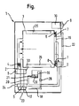
- the heat exchanger 5 is made of a thermally conductive composite material comprising polypropylene and 3% by weight of carbon nanotubes. Otherwise, the condensation dryer 1 is configured as a vented dryer 1. The arrows indicate the flow direction of the process air. The heat exchange in this heat exchanger 5 takes place by passing heat through this composite material.
- the condensation dryer 1 shown in the figure has a drum rotatable about a horizontal axis as a drying chamber 3, within which drivers 25 are mounted for movement of laundry items during a drum rotation.
- Supply air is fed in the process air duct 2 by means of a blower 6 from the supply air inlet 23 via an air-air heat exchanger 5 and an electric heater 4 through the drum 3.
- air heated by the electric heater 4 is heated from the rear, i. from the door 22 opposite side of the drum 3, passed through the perforated bottom in the drum 3.
- the laden with moisture process air is passed in a called exhaust duct portion of the process air duct 2 via the air-air heat exchanger 5 to an exhaust outlet 24.
- the process air flows through the filling opening of the drum 3 to a lint filter 16 within a door 22 closing the filling opening.
- the process air flow in the door 22 is deflected downwards and passed on to the air-to-air heat exchanger 5.
- the moisture absorbed by the process air from the items of laundry condenses there and is collected in a condensate tray 17.
- the condensate tray 17 is connected via a condensate channel 18, in which a pump 28 is located, to a condensate container 19, in which the condensate 29 originating from the condensate tray 17 is collected.
- the condensate container 19 comprises a lower container opening 21.
- a cleaning line 20 is arranged between the rinsing container 19 and the air-air heat exchanger 5.
- the air-air heat exchanger 5 can be cleaned by means of the amount of condensate 29 present in the condensate container 19 after a determined cleaning requirement.
- the air-air heat exchanger 5 made of a composite material of polypropylene and carbon nanotubes in this embodiment is relatively easy to clean.
- the condensate 29 used as flushing liquid had previously accumulated in the air-to-air heat exchanger 5 and pumped from the condensate pan 17 by means of the pump 28 via the condensate channel 18 into the condensate tank 19.
- the lower container opening 21 is opened and the condensate 29 through the cleaning line 20th passed into the air-to-air heat exchanger 5.
- the condensate 29 is collected in the condensate pan 17 and pumped back into the condensate tank 19. This cycle can be repeated.
- the drum 3 is mounted in the embodiment shown here at the rear bottom by means of a pivot bearing and front by means of a bearing plate 16, wherein the drum 3 rests with a brim on a sliding strip 8 on the bearing plate 7 and is held at the front end.
- the control of the dryer via a control device 10, which can be controlled by the user via an operating unit 9.
- the fan 6 and the drum 3 are driven by the motor 30.
Landscapes
- Engineering & Computer Science (AREA)
- Textile Engineering (AREA)
- Physics & Mathematics (AREA)
- Thermal Sciences (AREA)
- Mechanical Engineering (AREA)
- General Engineering & Computer Science (AREA)
- Compositions Of Macromolecular Compounds (AREA)
- Manufacture Of Macromolecular Shaped Articles (AREA)
Applications Claiming Priority (1)
| Application Number | Priority Date | Filing Date | Title |
|---|---|---|---|
| DE102009046680A DE102009046680A1 (de) | 2009-11-13 | 2009-11-13 | Hausgerät mit Wärmetauscher aus thermoplastischem Kunststoff enthaltendem Werkstoff, sowie solcher Wärmetauscher |
Publications (2)
| Publication Number | Publication Date |
|---|---|
| EP2322708A2 true EP2322708A2 (fr) | 2011-05-18 |
| EP2322708A3 EP2322708A3 (fr) | 2013-06-12 |
Family
ID=43773166
Family Applications (1)
| Application Number | Title | Priority Date | Filing Date |
|---|---|---|---|
| EP10190071.0A Withdrawn EP2322708A3 (fr) | 2009-11-13 | 2010-11-05 | Appareil ménager doté d'un échangeur thermique en matière synthétique thermoplastique, et un tel échangeur thermique |
Country Status (2)
| Country | Link |
|---|---|
| EP (1) | EP2322708A3 (fr) |
| DE (1) | DE102009046680A1 (fr) |
Cited By (6)
| Publication number | Priority date | Publication date | Assignee | Title |
|---|---|---|---|---|
| WO2013074227A1 (fr) * | 2011-11-14 | 2013-05-23 | General Electric Company | Procédé de récupération de panache |
| DE102011089757A1 (de) | 2011-12-23 | 2013-06-27 | BSH Bosch und Siemens Hausgeräte GmbH | Behälter mit Beheizbarkeit einer darin aufgenommenen Flüssigkeit |
| EP2746456A1 (fr) * | 2012-12-18 | 2014-06-25 | BSH Bosch und Siemens Hausgeräte GmbH | Appareil ménager avec accumulateur de chaleur latente et son procédé de fonctionnement |
| CN105986447A (zh) * | 2015-03-03 | 2016-10-05 | 青岛海尔洗衣机有限公司 | 排气式干衣机及其控制方法 |
| CN112301323A (zh) * | 2020-10-29 | 2021-02-02 | 佛山高砂工业窑炉有限公司 | 一种用于生产硅氧负极材料基于cvd工艺的加工设备 |
| EP3819423A1 (fr) * | 2019-11-07 | 2021-05-12 | Whirlpool Corporation | Procédé d'évacuation de la chaleur à partir d'un système de séchage rotatif de vêtements sur l'extérieur de l'appareil |
Families Citing this family (1)
| Publication number | Priority date | Publication date | Assignee | Title |
|---|---|---|---|---|
| DE102011081940A1 (de) * | 2011-09-01 | 2013-03-07 | BSH Bosch und Siemens Hausgeräte GmbH | Trockner mit einem Kreuzstromwärmetauscher und Verfahren zu seinem Betrieb |
Citations (6)
| Publication number | Priority date | Publication date | Assignee | Title |
|---|---|---|---|---|
| WO2000069958A1 (fr) | 1999-05-18 | 2000-11-23 | Atofina Research | Polymeres renforces |
| DE19958106A1 (de) | 1999-11-17 | 2001-02-22 | Joma Polytec Kunststofftechnik | Kreuzstrom-Wärmetauscher für Kondensationswäschetrockner |
| DE10218274A1 (de) | 2002-04-18 | 2003-11-06 | Joma Polytec Kunststofftechnik | Wärmetauscherplatte für einen Kreuzstromwärmetauscher |
| DE20221788U1 (de) | 2002-04-18 | 2007-09-13 | Joma-Polytec Kunststofftechnik Gmbh | Wärmetauschplatte für einen Kreuzstromtauscher |
| US20070232748A1 (en) | 2004-05-11 | 2007-10-04 | Olivier Guerret | Composite Materials Based on Carbon Nanotubes and Polymer Matrices and Processes for Obtaining Same |
| US20090134363A1 (en) | 2005-12-23 | 2009-05-28 | Arkema France | Method for synthesis of carbon nanotubes |
Family Cites Families (6)
| Publication number | Priority date | Publication date | Assignee | Title |
|---|---|---|---|---|
| DE8318395U1 (de) * | 1983-06-24 | 1983-10-20 | Bosch-Siemens Hausgeräte GmbH, 7000 Stuttgart | Haushalt-waeschetrockner |
| US20040206941A1 (en) * | 2000-11-22 | 2004-10-21 | Gurin Michael H. | Composition for enhancing conductivity of a carrier medium and method of use thereof |
| US20050126766A1 (en) * | 2003-09-16 | 2005-06-16 | Koila,Inc. | Nanostructure augmentation of surfaces for enhanced thermal transfer with improved contact |
| JP4520774B2 (ja) * | 2003-12-15 | 2010-08-11 | 臼井国際産業株式会社 | 熱交換器 |
| JP4631877B2 (ja) * | 2007-07-02 | 2011-02-16 | スターライト工業株式会社 | 樹脂製ヒートシンク |
| EP2201079B1 (fr) * | 2007-09-14 | 2017-08-23 | Henkel AG & Co. KGaA | Composition thermiquement conductrice |
-
2009
- 2009-11-13 DE DE102009046680A patent/DE102009046680A1/de not_active Withdrawn
-
2010
- 2010-11-05 EP EP10190071.0A patent/EP2322708A3/fr not_active Withdrawn
Patent Citations (6)
| Publication number | Priority date | Publication date | Assignee | Title |
|---|---|---|---|---|
| WO2000069958A1 (fr) | 1999-05-18 | 2000-11-23 | Atofina Research | Polymeres renforces |
| DE19958106A1 (de) | 1999-11-17 | 2001-02-22 | Joma Polytec Kunststofftechnik | Kreuzstrom-Wärmetauscher für Kondensationswäschetrockner |
| DE10218274A1 (de) | 2002-04-18 | 2003-11-06 | Joma Polytec Kunststofftechnik | Wärmetauscherplatte für einen Kreuzstromwärmetauscher |
| DE20221788U1 (de) | 2002-04-18 | 2007-09-13 | Joma-Polytec Kunststofftechnik Gmbh | Wärmetauschplatte für einen Kreuzstromtauscher |
| US20070232748A1 (en) | 2004-05-11 | 2007-10-04 | Olivier Guerret | Composite Materials Based on Carbon Nanotubes and Polymer Matrices and Processes for Obtaining Same |
| US20090134363A1 (en) | 2005-12-23 | 2009-05-28 | Arkema France | Method for synthesis of carbon nanotubes |
Cited By (8)
| Publication number | Priority date | Publication date | Assignee | Title |
|---|---|---|---|---|
| WO2013074227A1 (fr) * | 2011-11-14 | 2013-05-23 | General Electric Company | Procédé de récupération de panache |
| DE102011089757A1 (de) | 2011-12-23 | 2013-06-27 | BSH Bosch und Siemens Hausgeräte GmbH | Behälter mit Beheizbarkeit einer darin aufgenommenen Flüssigkeit |
| EP2746456A1 (fr) * | 2012-12-18 | 2014-06-25 | BSH Bosch und Siemens Hausgeräte GmbH | Appareil ménager avec accumulateur de chaleur latente et son procédé de fonctionnement |
| CN105986447A (zh) * | 2015-03-03 | 2016-10-05 | 青岛海尔洗衣机有限公司 | 排气式干衣机及其控制方法 |
| EP3819423A1 (fr) * | 2019-11-07 | 2021-05-12 | Whirlpool Corporation | Procédé d'évacuation de la chaleur à partir d'un système de séchage rotatif de vêtements sur l'extérieur de l'appareil |
| US11851807B2 (en) | 2019-11-07 | 2023-12-26 | Whirlpool Corporation | Method of removing heat from a clothes tumbling system on the outside of the cabinet |
| US12157969B2 (en) | 2019-11-07 | 2024-12-03 | Whirlpool Corporation | Method of removing heat from a clothes tumbling system on the outside of the cabinet |
| CN112301323A (zh) * | 2020-10-29 | 2021-02-02 | 佛山高砂工业窑炉有限公司 | 一种用于生产硅氧负极材料基于cvd工艺的加工设备 |
Also Published As
| Publication number | Publication date |
|---|---|
| EP2322708A3 (fr) | 2013-06-12 |
| DE102009046680A1 (de) | 2011-05-19 |
Similar Documents
| Publication | Publication Date | Title |
|---|---|---|
| EP2322708A2 (fr) | Appareil ménager doté d'un échangeur thermique en matière synthétique thermoplastique, et un tel échangeur thermique | |
| EP2358937B1 (fr) | Séchoir par condensation comportant une pompe à chaleur, et procédé pour son exploitation | |
| DE102008033388B4 (de) | Trockner mit Wärmepumpenkreis | |
| EP0411080B1 (fr) | Seche-linge | |
| DE102014219457B4 (de) | Trockner mit einer Wärmepumpe und einer Zusatzheizung sowie Verfahren zu seinem Betrieb | |
| DE102008007726B4 (de) | Abgaswärme-Rückgewinnungssystem | |
| WO2008080831A1 (fr) | Séchoir à condensation comprenant une pompe à chaleur ainsi que procédé de fonctionnement | |
| EP2605691B1 (fr) | Procédé et dispositif pour sécher de l'air humide | |
| EP1737334B1 (fr) | Methode de lavage d'une lave vaiselle, et lave vaiselle | |
| EP2115208A1 (fr) | Sèche-linge à condensation équipé d'une pompe à chaleur et procédé pour faire fonctionner ce sèche-linge | |
| EP1651090B1 (fr) | Lave-vaisselle | |
| EP2140061B1 (fr) | Sèche-linge à condensation et procédé permettant de faire fonctionner un sèche-linge à condensation | |
| EP2065509A1 (fr) | Sèche-linge à évacuation d'air doté d'une pompe à chaleur et d'un premier ventilateur | |
| WO2006029953A1 (fr) | Procédé de séchage pour un appareil électroménager et appareil électroménager permettant la mise en oeuvre dudit procédé | |
| EP2072656B1 (fr) | Appareil de séchage de linge et procédé de fonctionnement de celui-ci | |
| EP1651091A1 (fr) | Machine a laver la vaisselle a tube de chauffage | |
| EP2565321B1 (fr) | Séchoir doté d'un échangeur thermique à flux croisé et son procédé de fonctionnement | |
| DE2914859A1 (de) | Waeschetrockner | |
| EP2746456A1 (fr) | Appareil ménager avec accumulateur de chaleur latente et son procédé de fonctionnement | |
| DE202007000825U1 (de) | Kondensationstrockner mit einer Wärmepumpe | |
| EP1838204B1 (fr) | Lave-vaisselle comprenant un dispositif de sechage | |
| DE102007018784A1 (de) | Automatische, zum Trocknen eingerichtete Waschmaschine | |
| EP2852702B1 (fr) | Procédé permettant de faire fonctionner un séchoir comportant un accumulateur à changement de phase, et séchoir correspondant | |
| DE102006005809B4 (de) | Kondensationstrockner enthaltend ein Kondensatorgehäuse mit mindestens einer dünnen Wand | |
| WO2008145555A2 (fr) | Sèche-linge à condensation |
Legal Events
| Date | Code | Title | Description |
|---|---|---|---|
| PUAI | Public reference made under article 153(3) epc to a published international application that has entered the european phase |
Free format text: ORIGINAL CODE: 0009012 |
|
| AK | Designated contracting states |
Kind code of ref document: A2 Designated state(s): AL AT BE BG CH CY CZ DE DK EE ES FI FR GB GR HR HU IE IS IT LI LT LU LV MC MK MT NL NO PL PT RO RS SE SI SK SM TR |
|
| AX | Request for extension of the european patent |
Extension state: BA ME |
|
| PUAL | Search report despatched |
Free format text: ORIGINAL CODE: 0009013 |
|
| RIC1 | Information provided on ipc code assigned before grant |
Ipc: D06F 58/24 20060101AFI20130429BHEP Ipc: C23C 16/26 20060101ALI20130429BHEP Ipc: F28F 21/06 20060101ALI20130429BHEP |
|
| AK | Designated contracting states |
Kind code of ref document: A3 Designated state(s): AL AT BE BG CH CY CZ DE DK EE ES FI FR GB GR HR HU IE IS IT LI LT LU LV MC MK MT NL NO PL PT RO RS SE SI SK SM TR |
|
| AX | Request for extension of the european patent |
Extension state: BA ME |
|
| 17P | Request for examination filed |
Effective date: 20131212 |
|
| RBV | Designated contracting states (corrected) |
Designated state(s): AL AT BE BG CH CY CZ DE DK EE ES FI FR GB GR HR HU IE IS IT LI LT LU LV MC MK MT NL NO PL PT RO RS SE SI SK SM TR |
|
| RAP1 | Party data changed (applicant data changed or rights of an application transferred) |
Owner name: BSH HAUSGERAETE GMBH |
|
| 17Q | First examination report despatched |
Effective date: 20170524 |
|
| STAA | Information on the status of an ep patent application or granted ep patent |
Free format text: STATUS: THE APPLICATION IS DEEMED TO BE WITHDRAWN |
|
| 18D | Application deemed to be withdrawn |
Effective date: 20171005 |