EP2322733A1 - Modulares Bauelement zur Herstellung von Hohlräumen, z.B. in gelüftete Unterboden, Bodenplatte und Decke - Google Patents
Modulares Bauelement zur Herstellung von Hohlräumen, z.B. in gelüftete Unterboden, Bodenplatte und Decke Download PDFInfo
- Publication number
- EP2322733A1 EP2322733A1 EP10190908A EP10190908A EP2322733A1 EP 2322733 A1 EP2322733 A1 EP 2322733A1 EP 10190908 A EP10190908 A EP 10190908A EP 10190908 A EP10190908 A EP 10190908A EP 2322733 A1 EP2322733 A1 EP 2322733A1
- Authority
- EP
- European Patent Office
- Prior art keywords
- modular
- elements
- connecting portions
- interaxial
- seats
- Prior art date
- Legal status (The legal status is an assumption and is not a legal conclusion. Google has not performed a legal analysis and makes no representation as to the accuracy of the status listed.)
- Granted
Links
Images


Classifications
-
- E—FIXED CONSTRUCTIONS
- E04—BUILDING
- E04B—GENERAL BUILDING CONSTRUCTIONS; WALLS, e.g. PARTITIONS; ROOFS; FLOORS; CEILINGS; INSULATION OR OTHER PROTECTION OF BUILDINGS
- E04B5/00—Floors; Floor construction with regard to insulation; Connections specially adapted therefor
- E04B5/16—Load-carrying floor structures wholly or partly cast or similarly formed in situ
- E04B5/32—Floor structures wholly cast in situ with or without form units or reinforcements
- E04B5/36—Floor structures wholly cast in situ with or without form units or reinforcements with form units as part of the floor
-
- E—FIXED CONSTRUCTIONS
- E04—BUILDING
- E04B—GENERAL BUILDING CONSTRUCTIONS; WALLS, e.g. PARTITIONS; ROOFS; FLOORS; CEILINGS; INSULATION OR OTHER PROTECTION OF BUILDINGS
- E04B5/00—Floors; Floor construction with regard to insulation; Connections specially adapted therefor
- E04B5/48—Special adaptations of floors for incorporating ducts, e.g. for heating or ventilating
Definitions
- the present invention relates to a modular building element for forming cavities, for example, ventilated under-floor spaces and floors and ceilings.
- a first solution for forming such structures is described in GB 1 129 892 A , US 1 805 483 A and US 1 924 035 A .
- the cavities are formed by arranging side by side a series of elongate arched elements which together form a linear cavity.
- the elements are joined together at their ends and have a series of coupling positions which enable the overall length of the cavity to be adjusted. This solution does not permit the formation of cavities which extend along two different axes.
- These forms typically comprise a cover with a square or rectangular base which can rest on a support surface, normally a floor or a weak mix of concrete, by means of at least four supports connected by a corresponding number of arches. Laying takes place by the fitting together of the arches of two adjoining elements with partial superimposition thereof, so as to form a solid and continuous surface and to permit the rapid construction of a platform which can be walked on and on top of which concrete is poured.
- a space is thus defined beneath the concrete, permitting adequate ventilation and, more generally, protection from moisture, or the insertion of installations of various types.
- the forms are cut at the edges of the surface to be covered so as to achieve complete coverage.
- patent application WO 2001 088298 provides for the use of an accessory element that enables two adjacent forms to be connected by positioning them a greater distance apart than is permitted by fitting them together, or by filling the remaining space at the edge if the forms are laid continuously.
- this accessory is constructed as an arched duct which can be fitted in the arches that are present in the forms.
- this solution has been found not to be very practical or economic in use since it requires the use of further elements, in addition to the forms, for the formation of the cavities.
- the accessories described in the above-mentioned patent application have a closed side wall which, in some cases, has to be opened suitably during installation to prevent the creation of discontinuities in the cavity, thus also requiring the use of additional tools and manpower for installation.
- Another solution consists in filling the empty space at the periphery of the positioned elements with pieces of polystyrene. These pieces are often shaped as necessary beforehand. When these elements are used at the periphery, however, an obstruction to the ventilation of the foundations results at the edge, thus limiting the expulsion of the moisture enclosed in the peripheral walls, particularly where reconstruction is involved.
- the present invention has some considerable advantages.
- the main advantage is that, by virtue of the variability of the interaxial spacing, the modular building element according to the present invention permits the formation of cavities, for example, under-floor spaces and ventilated floors and ceilings, in regular surfaces of any dimensions, without the need to use accessory elements or modifications to the structure of the modular element. Further advantages, features and methods of use of the present invention will become clear from the following detailed description of some embodiments which are given by way of non-limiting example. Reference is made to the figures of the appended drawings, in which:
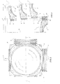
- a modular building element is generally indicated 1. It comprises a covering surface 10 which is arranged substantially horizontally and, in particular, extends substantially parallel to a laying surface 100, shown schematically in Figure 2 , on top of which laying surface 100 the cavity is formed in accordance with the procedures which will be described below.
- horizontal relates to the general orientation of the surface 10 relative to a support surface, which thus corresponds to the laying surface 100, after the laying of the modular element 1.
- the covering surface 10 is substantially dome-shaped and extends over a square base, as shown in Figure 3 .
- the covering surface could have many other shapes and could also have a rectangular base.
- a triangular shape or a polygonal shape with a number of sides greater than four may also be provided for.
- the present description relates to the domed shape and is thus provided purely by way of non-limiting example.
- the horizontal surface 10 is supported by four supports 11 which keep the surface 10 raised from a support surface in similar manner to the modular elements for forming cavities produced in accordance with the prior art.
- the element 1 further comprises, between two adjacent supports 11, respective first and second connecting portions 2 and 3 which, in the embodiment described, are arch-shaped and which, when the modular element 1 is resting on the laying surface 100 on the supports 11, define four respective openings 12 and a space beneath the surface 10.
- the connecting portions 2 and 3 extend from the laying surface 100, forming the above-mentioned arches.
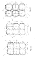
- the first connecting portion 2 has a plurality of seats 22 on each of which a projection 31 that is present on the portion 3 can be superimposed. More precisely, when the projection 31 of an element 1 is placed in one of the seats 22 of a further element 1, a male/female connection is formed between the two elements, thus creating a continuous covering surface which is thus suitable for forming a continuous cavity, as can be seen in Figure 5A . In other words, by means of the connection, the openings 12 of two modular elements 1 are put into communication, thus obtaining a single continuous space beneath the surfaces 10.
- the cavity thus formed extends along two intersecting axes x and y, that is, with a two-dimensional development.
- the cavity may, of course, extend along a greater number of intersecting axes.
- a triangular shape not shown in the drawings, there will be three openings 12 and the cavity will extend along three intersecting axes.
- the presence of a plurality of seats 22 enables two modular elements 1 to be connected in different operative positions in each of which the elements 1 will have different interaxial spacings i.
- the drawing shows the situation in which the connecting portion 2 has three seats 22 so as to be able to make the connection between two modular elements 1 with interaxial spacings of i, i' and i", respectively.
- interaxial spacings i, i' and i" defined between two adjoining elements 1 may be different or equal along the intersecting axes (x, y) but may also be different or equal along the same axis.
- the useful space defined beneath two adjoining elements 1 is variable in dependence on the actual value of the interaxial spacings i, i' and i" between the two adjoining modular elements.
- the useful space defined beneath two adjoining elements 1, that is, the space defined beneath the two mutually connected adjoining modular elements, is less than the sum of the spaces of the two individual modular elements 1 since the two adjoining modular elements 1 are at least partially superimposed.
- the interaxial spacing is evaluated with respect to an axis of symmetry A of the dome between adjoining elements and delimited by two half-surfaces 10 increased by the connecting portions 2 and 3 but, naturally, different references may also be taken into consideration for the evaluation of the spacing between two adjacent modular elements 1 during laying.
- the facility to connect the elements 1 with different interaxial spacings enables the same type of element 1 to be used for covering surfaces which have different dimensions, even along both axes x and y, and consequently permits complete or almost complete coverage of the designed cavity or the cavity to be formed. That is, the summation of the variations of the interaxial spacings covers the portion which would remain exposed if the interaxial spacing were constant as it is at the moment and in the prior art.
- the adjoining elements can completely or almost completely cover the space which would remain between the series of elements and the actual periphery to be covered if the elements were of constant interaxial spacing, in any case forming a continuous cavity which extends along two intersecting axes.
- the modular element 1 preferably has a square or quadrangular shape in plan with the supports 11 arranged at the corners thereof and the connecting portions 2 and 3 arranged at the sides of the square or rectangle.
- Conceptually similar solutions in which the same number of first and second connecting portions 2 and 3 are present and are also arranged on respective sides are also applicable to shapes that are polygonal in plan with even numbers of sides.
- modular elements with a different number of first connecting portions 2 in comparison with the number of second portions 3 will be used.
- two different types of elements 1 with complementary numbers of first and second portions will therefore be used.
- modular elements with one first connecting portion and two second connecting portions will be used, associated with modular elements which instead, have two first connecting portions and one second connecting portion.
- this could have more than four supports 11 and a covering surface 10 which, by way of example, is concave, flat, or convex, with the upper portion arranged to form or accept a lid which permits inspection of the cavity.
- the element 1 upon the assumption that the element 1 is characterized by four supports, the element 1 comprises two first connecting portions 2 arranged on adjacent sides and two second connecting portions 3 arranged on the other two adjacent sides.
- first connecting portions 2 have a plurality of ridges 21 which define the seats 22 and enable two elements 1 to be kept locked in the preselected position once they have been connected.
- This feature provides the structure with stability and renders it suitable for walking on during the laying stages.
- FIGS. 6A to 6D show the connection between two modular elements 1 according to the embodiment described above and according to three further embodiments.
- the projection 31 formed in the connecting portion 3 is inserted in one of the seats 22 in the portion 2, thus enabling one of the three possible interaxial spacings between the elements to be achieved.
- This connection thus provides the surfaces 10 of the two elements with continuity, defining a continuous surface on top of which concrete can be poured so as to obtain the desired cavity, for example, to form under-floor spaces or ventilated floors and ceilings.
- Figure 6B shows an alternative embodiment in which the portion 2 has a smooth surface 23 on which the second portion 3 will be placed, optionally in the region of the projection 31 which, if desired, can be fixed in the preselected position by any fixing means such as screws, nails, rivets, or the like, not shown in the drawing. It is suggested, although not necessary, that the portion 2 be provided with an end block 24 which enables the portion 3 to be held on the smooth surface 23, allowing one of the infinite number of possible interaxial spacings to be formed.
- a third embodiment is shown in Figure 6C in which the first portion 2 is provided with one or more pins 25 which can be fixed in different positions on the smooth surface 23.
- the pin or pins is or are inserted in a suitable seat or seats 32 of the second connecting portion 3 enabling one of the infinite number of possible non-fixed interaxial spacings to be set.
- FIG. 6D a further embodiment is shown in Figure 6D in which, instead, there are one or more pins 33 in the second connecting portion 3; these pins 33 are housed in one or more suitable seats 26 formed in the portion 2, thus enabling a plurality of interaxial spacings to be achieved.
Landscapes
- Engineering & Computer Science (AREA)
- Architecture (AREA)
- Physics & Mathematics (AREA)
- Electromagnetism (AREA)
- Civil Engineering (AREA)
- Structural Engineering (AREA)
- Floor Finish (AREA)
- Building Environments (AREA)
- Special Spraying Apparatus (AREA)
- Instructional Devices (AREA)
- Developing Agents For Electrophotography (AREA)
Applications Claiming Priority (1)
| Application Number | Priority Date | Filing Date | Title |
|---|---|---|---|
| ITPD2009A000335A IT1396973B1 (it) | 2009-11-12 | 2009-11-12 | Elemento edilizio modulare per la realizzazione di intercapedini in genere, ad esempio vespai, pavimenti e tetti areati |
Publications (3)
| Publication Number | Publication Date |
|---|---|
| EP2322733A1 true EP2322733A1 (de) | 2011-05-18 |
| EP2322733B1 EP2322733B1 (de) | 2013-05-08 |
| EP2322733B8 EP2322733B8 (de) | 2013-07-10 |
Family
ID=42270583
Family Applications (1)
| Application Number | Title | Priority Date | Filing Date |
|---|---|---|---|
| EP20100190908 Active EP2322733B8 (de) | 2009-11-12 | 2010-11-11 | Modulares Bauelement zur Herstellung von Hohlräumen, z. B. in gelüftete Unterboden, Bodenplatte und Decke |
Country Status (2)
| Country | Link |
|---|---|
| EP (1) | EP2322733B8 (de) |
| IT (1) | IT1396973B1 (de) |
Cited By (6)
| Publication number | Priority date | Publication date | Assignee | Title |
|---|---|---|---|---|
| ITTV20110168A1 (it) * | 2011-12-06 | 2013-06-07 | T P S S R L | Dispositivo di accoppiamento e fissaggio per casseri a perdere. |
| WO2015138427A1 (en) * | 2014-03-12 | 2015-09-17 | Miskovich Joseph S | Modular construction conduit unit |
| US9739046B2 (en) | 2014-03-12 | 2017-08-22 | Joseph S. Miskovich | Modular stormwater retention and management system |
| USD840498S1 (en) | 2017-08-09 | 2019-02-12 | J.M. Sales Associates, Inc. | Modular fluid retention and management tray |
| US10597861B2 (en) | 2014-03-12 | 2020-03-24 | J.M. Sales Associates, Inc. | Modular stormwater retention system |
| EP3653803A3 (de) * | 2016-10-12 | 2020-09-16 | Advanced Drainage Systems, Inc. | Kuppelförmige regenwasserkammer |
Families Citing this family (1)
| Publication number | Priority date | Publication date | Assignee | Title |
|---|---|---|---|---|
| US9580899B2 (en) * | 2015-06-18 | 2017-02-28 | Rotondo Environmental Solutions, Llc | Storm-pod system for collecting and utilizing storm water |
Citations (11)
| Publication number | Priority date | Publication date | Assignee | Title |
|---|---|---|---|---|
| US1805483A (en) | 1929-09-07 | 1931-05-19 | Ernest E Fletcher | Floor construction |
| US1924035A (en) | 1930-07-01 | 1933-08-22 | Max S Goldsmith | Concrete floor construction |
| GB1129892A (en) | 1965-11-08 | 1968-10-09 | Atlas Stone Company Ltd | Improvements relating to the construction of floors or roofs |
| IT1253374B (it) | 1991-10-10 | 1995-08-08 | Elemento prefabbricato modulare per edifici abitativi | |
| EP0803618A2 (de) * | 1996-04-23 | 1997-10-29 | Valerio Pontarolo | Modulares Element zur Unterstützung und Lüftung von Decken |
| EP0969157A2 (de) * | 1998-07-03 | 2000-01-05 | DALIFORM S.r.l. | Modulares vorgefertigtes Element für Gebaüde |
| EP1092817A2 (de) * | 1999-10-12 | 2001-04-18 | DALIFORM S.r.l. | Verbessertes Schalungselement für die Herstellung von Decken, Dächern und dergleichen |
| WO2001088298A1 (en) | 2000-05-16 | 2001-11-22 | Valerio Pontarolo | Accessory for modular elements for the support and ventilation of crawl spaces, floor structures, floors or similar articles in the building field |
| WO2003069074A1 (en) * | 2002-02-15 | 2003-08-21 | Tipspit Holding B.V. | Assembly of structural elements, structural element and use of such an assembly |
| EP1605113A1 (de) * | 2004-06-11 | 2005-12-14 | GEOPLAST S.p.A. | Modulelemente zum Aufbau von Doppelboden aus Stahlbeton |
| EP1978174A2 (de) * | 2007-04-04 | 2008-10-08 | T.P.S. S.R.L. | Verfahren zum Erhalten eines modularen Abdeckelements, insbesondere für belüftete Böden oder Bodenplatten in Gebäuden |
Family Cites Families (1)
| Publication number | Priority date | Publication date | Assignee | Title |
|---|---|---|---|---|
| GB1203591A (en) * | 1967-08-07 | 1970-08-26 | John Cornelius Leemhuis | Structural member |
-
2009
- 2009-11-12 IT ITPD2009A000335A patent/IT1396973B1/it active
-
2010
- 2010-11-11 EP EP20100190908 patent/EP2322733B8/de active Active
Patent Citations (11)
| Publication number | Priority date | Publication date | Assignee | Title |
|---|---|---|---|---|
| US1805483A (en) | 1929-09-07 | 1931-05-19 | Ernest E Fletcher | Floor construction |
| US1924035A (en) | 1930-07-01 | 1933-08-22 | Max S Goldsmith | Concrete floor construction |
| GB1129892A (en) | 1965-11-08 | 1968-10-09 | Atlas Stone Company Ltd | Improvements relating to the construction of floors or roofs |
| IT1253374B (it) | 1991-10-10 | 1995-08-08 | Elemento prefabbricato modulare per edifici abitativi | |
| EP0803618A2 (de) * | 1996-04-23 | 1997-10-29 | Valerio Pontarolo | Modulares Element zur Unterstützung und Lüftung von Decken |
| EP0969157A2 (de) * | 1998-07-03 | 2000-01-05 | DALIFORM S.r.l. | Modulares vorgefertigtes Element für Gebaüde |
| EP1092817A2 (de) * | 1999-10-12 | 2001-04-18 | DALIFORM S.r.l. | Verbessertes Schalungselement für die Herstellung von Decken, Dächern und dergleichen |
| WO2001088298A1 (en) | 2000-05-16 | 2001-11-22 | Valerio Pontarolo | Accessory for modular elements for the support and ventilation of crawl spaces, floor structures, floors or similar articles in the building field |
| WO2003069074A1 (en) * | 2002-02-15 | 2003-08-21 | Tipspit Holding B.V. | Assembly of structural elements, structural element and use of such an assembly |
| EP1605113A1 (de) * | 2004-06-11 | 2005-12-14 | GEOPLAST S.p.A. | Modulelemente zum Aufbau von Doppelboden aus Stahlbeton |
| EP1978174A2 (de) * | 2007-04-04 | 2008-10-08 | T.P.S. S.R.L. | Verfahren zum Erhalten eines modularen Abdeckelements, insbesondere für belüftete Böden oder Bodenplatten in Gebäuden |
Cited By (11)
| Publication number | Priority date | Publication date | Assignee | Title |
|---|---|---|---|---|
| ITTV20110168A1 (it) * | 2011-12-06 | 2013-06-07 | T P S S R L | Dispositivo di accoppiamento e fissaggio per casseri a perdere. |
| EP2602396A1 (de) * | 2011-12-06 | 2013-06-12 | T.P.S. S.R.L. | Koppel- und Befestigungsvorrichtung für verlorene Schalung |
| WO2015138427A1 (en) * | 2014-03-12 | 2015-09-17 | Miskovich Joseph S | Modular construction conduit unit |
| US9371938B2 (en) | 2014-03-12 | 2016-06-21 | Joseph S. Miskovich | Modular construction conduit unit |
| US9739046B2 (en) | 2014-03-12 | 2017-08-22 | Joseph S. Miskovich | Modular stormwater retention and management system |
| US10597861B2 (en) | 2014-03-12 | 2020-03-24 | J.M. Sales Associates, Inc. | Modular stormwater retention system |
| EP3653803A3 (de) * | 2016-10-12 | 2020-09-16 | Advanced Drainage Systems, Inc. | Kuppelförmige regenwasserkammer |
| EP3526414B1 (de) * | 2016-10-12 | 2022-06-29 | Advanced Drainage Systems, Inc. | Kuppelförmige regenwasserkammer |
| USD840498S1 (en) | 2017-08-09 | 2019-02-12 | J.M. Sales Associates, Inc. | Modular fluid retention and management tray |
| USD868934S1 (en) | 2017-08-09 | 2019-12-03 | J.M. Sales Associates, Inc. | Modular fluid retention and management tray |
| USD868935S1 (en) | 2017-08-09 | 2019-12-03 | J.M. Sales Associates, Inc. | Modular fluid retention and management tray |
Also Published As
| Publication number | Publication date |
|---|---|
| ITPD20090335A1 (it) | 2011-05-13 |
| EP2322733B8 (de) | 2013-07-10 |
| EP2322733B1 (de) | 2013-05-08 |
| IT1396973B1 (it) | 2012-12-20 |
Similar Documents
| Publication | Publication Date | Title |
|---|---|---|
| EP2322733B1 (de) | Modulares Bauelement zur Herstellung von Hohlräumen, z. B. in gelüftete Unterboden, Bodenplatte und Decke | |
| US20120255624A1 (en) | Drainage body | |
| CA2852645C (en) | Masonry block system | |
| US20120096797A1 (en) | Web structure for knockdown insulating concrete block | |
| US20070214740A1 (en) | Cavity Former | |
| RU2601883C1 (ru) | Пустотообразующий элемент несъёмной опалубки для железобетонных многопустотных плитных конструкций | |
| US20180187429A1 (en) | Multi-functional tray | |
| US8997419B1 (en) | Modular floor tile system with expansion joint | |
| TR201909863T4 (tr) | Bir plastik infiltrasyon ünitesi, birden çok plastik infiltrasyon ünitesini içeren bir sistem. | |
| US20140305062A1 (en) | Masonry units and structures formed therefrom | |
| US11851892B2 (en) | Modular supporting element for making raised and/or ventilated reinforced concrete floors | |
| CN107002412B (zh) | 铺地模块 | |
| NZ522774A (en) | Accessory for modular elements for the support and ventilation of crawl spaces, floor structures, floors or similar articles in the building field | |
| EP1736607B1 (de) | Füll- und Dämmelement und Bausystem mit solch einem Element | |
| US20140196392A1 (en) | Masonry units and structures formed therefrom | |
| WO2012158037A1 (en) | Assembly of tiles for forming a floor | |
| WO2023002267A1 (en) | Modular formwork for the construction of reinforced concrete ribbed floors with specially configured spacers | |
| US20060248837A1 (en) | Building panel | |
| CA3045920C (en) | Masonry block system | |
| AU2015238916B2 (en) | Closed void former for inclusion in concrete slabs | |
| US20100115869A1 (en) | Connecting and plugging element for modular floor construction | |
| EP2053181B1 (de) | Modulare Schalung zur Erzeugung von armierten kreuzförmigen Betondecken | |
| CA3063754C (en) | Vented floor arrangement and a kit of parts for use in assembling the floor | |
| US20230287691A1 (en) | Modular element system for the installation of concrete raised floors and related process | |
| CA2594374C (en) | Extruded permanent form-work for concrete |
Legal Events
| Date | Code | Title | Description |
|---|---|---|---|
| PUAI | Public reference made under article 153(3) epc to a published international application that has entered the european phase |
Free format text: ORIGINAL CODE: 0009012 |
|
| AK | Designated contracting states |
Kind code of ref document: A1 Designated state(s): AL AT BE BG CH CY CZ DE DK EE ES FI FR GB GR HR HU IE IS IT LI LT LU LV MC MK MT NL NO PL PT RO RS SE SI SK SM TR |
|
| AX | Request for extension of the european patent |
Extension state: BA ME |
|
| 17P | Request for examination filed |
Effective date: 20111118 |
|
| GRAP | Despatch of communication of intention to grant a patent |
Free format text: ORIGINAL CODE: EPIDOSNIGR1 |
|
| GRAS | Grant fee paid |
Free format text: ORIGINAL CODE: EPIDOSNIGR3 |
|
| GRAA | (expected) grant |
Free format text: ORIGINAL CODE: 0009210 |
|
| AK | Designated contracting states |
Kind code of ref document: B1 Designated state(s): AL AT BE BG CH CY CZ DE DK EE ES FI FR GB GR HR HU IE IS IT LI LT LU LV MC MK MT NL NO PL PT RO RS SE SI SK SM TR |
|
| REG | Reference to a national code |
Ref country code: GB Ref legal event code: FG4D |
|
| REG | Reference to a national code |
Ref country code: AT Ref legal event code: REF Ref document number: 611186 Country of ref document: AT Kind code of ref document: T Effective date: 20130515 Ref country code: CH Ref legal event code: EP |
|
| REG | Reference to a national code |
Ref country code: IE Ref legal event code: FG4D |
|
| REG | Reference to a national code |
Ref country code: DE Ref legal event code: R096 Ref document number: 602010006893 Country of ref document: DE Effective date: 20130704 |
|
| REG | Reference to a national code |
Ref country code: AT Ref legal event code: MK05 Ref document number: 611186 Country of ref document: AT Kind code of ref document: T Effective date: 20130508 |
|
| REG | Reference to a national code |
Ref country code: LT Ref legal event code: MG4D |
|
| REG | Reference to a national code |
Ref country code: NL Ref legal event code: VDEP Effective date: 20130508 |
|
| PG25 | Lapsed in a contracting state [announced via postgrant information from national office to epo] |
Ref country code: IS Free format text: LAPSE BECAUSE OF FAILURE TO SUBMIT A TRANSLATION OF THE DESCRIPTION OR TO PAY THE FEE WITHIN THE PRESCRIBED TIME-LIMIT Effective date: 20130908 Ref country code: SI Free format text: LAPSE BECAUSE OF FAILURE TO SUBMIT A TRANSLATION OF THE DESCRIPTION OR TO PAY THE FEE WITHIN THE PRESCRIBED TIME-LIMIT Effective date: 20130508 Ref country code: ES Free format text: LAPSE BECAUSE OF FAILURE TO SUBMIT A TRANSLATION OF THE DESCRIPTION OR TO PAY THE FEE WITHIN THE PRESCRIBED TIME-LIMIT Effective date: 20130819 Ref country code: PT Free format text: LAPSE BECAUSE OF FAILURE TO SUBMIT A TRANSLATION OF THE DESCRIPTION OR TO PAY THE FEE WITHIN THE PRESCRIBED TIME-LIMIT Effective date: 20130909 Ref country code: FI Free format text: LAPSE BECAUSE OF FAILURE TO SUBMIT A TRANSLATION OF THE DESCRIPTION OR TO PAY THE FEE WITHIN THE PRESCRIBED TIME-LIMIT Effective date: 20130508 Ref country code: SE Free format text: LAPSE BECAUSE OF FAILURE TO SUBMIT A TRANSLATION OF THE DESCRIPTION OR TO PAY THE FEE WITHIN THE PRESCRIBED TIME-LIMIT Effective date: 20130508 Ref country code: GR Free format text: LAPSE BECAUSE OF FAILURE TO SUBMIT A TRANSLATION OF THE DESCRIPTION OR TO PAY THE FEE WITHIN THE PRESCRIBED TIME-LIMIT Effective date: 20130809 Ref country code: LT Free format text: LAPSE BECAUSE OF FAILURE TO SUBMIT A TRANSLATION OF THE DESCRIPTION OR TO PAY THE FEE WITHIN THE PRESCRIBED TIME-LIMIT Effective date: 20130508 Ref country code: NO Free format text: LAPSE BECAUSE OF FAILURE TO SUBMIT A TRANSLATION OF THE DESCRIPTION OR TO PAY THE FEE WITHIN THE PRESCRIBED TIME-LIMIT Effective date: 20130808 Ref country code: AT Free format text: LAPSE BECAUSE OF FAILURE TO SUBMIT A TRANSLATION OF THE DESCRIPTION OR TO PAY THE FEE WITHIN THE PRESCRIBED TIME-LIMIT Effective date: 20130508 |
|
| PG25 | Lapsed in a contracting state [announced via postgrant information from national office to epo] |
Ref country code: PL Free format text: LAPSE BECAUSE OF FAILURE TO SUBMIT A TRANSLATION OF THE DESCRIPTION OR TO PAY THE FEE WITHIN THE PRESCRIBED TIME-LIMIT Effective date: 20130508 Ref country code: BG Free format text: LAPSE BECAUSE OF FAILURE TO SUBMIT A TRANSLATION OF THE DESCRIPTION OR TO PAY THE FEE WITHIN THE PRESCRIBED TIME-LIMIT Effective date: 20130808 Ref country code: RS Free format text: LAPSE BECAUSE OF FAILURE TO SUBMIT A TRANSLATION OF THE DESCRIPTION OR TO PAY THE FEE WITHIN THE PRESCRIBED TIME-LIMIT Effective date: 20130508 Ref country code: HR Free format text: LAPSE BECAUSE OF FAILURE TO SUBMIT A TRANSLATION OF THE DESCRIPTION OR TO PAY THE FEE WITHIN THE PRESCRIBED TIME-LIMIT Effective date: 20130508 Ref country code: CY Free format text: LAPSE BECAUSE OF FAILURE TO SUBMIT A TRANSLATION OF THE DESCRIPTION OR TO PAY THE FEE WITHIN THE PRESCRIBED TIME-LIMIT Effective date: 20130508 |
|
| PG25 | Lapsed in a contracting state [announced via postgrant information from national office to epo] |
Ref country code: LV Free format text: LAPSE BECAUSE OF FAILURE TO SUBMIT A TRANSLATION OF THE DESCRIPTION OR TO PAY THE FEE WITHIN THE PRESCRIBED TIME-LIMIT Effective date: 20130508 |
|
| PG25 | Lapsed in a contracting state [announced via postgrant information from national office to epo] |
Ref country code: SK Free format text: LAPSE BECAUSE OF FAILURE TO SUBMIT A TRANSLATION OF THE DESCRIPTION OR TO PAY THE FEE WITHIN THE PRESCRIBED TIME-LIMIT Effective date: 20130508 Ref country code: CZ Free format text: LAPSE BECAUSE OF FAILURE TO SUBMIT A TRANSLATION OF THE DESCRIPTION OR TO PAY THE FEE WITHIN THE PRESCRIBED TIME-LIMIT Effective date: 20130508 Ref country code: EE Free format text: LAPSE BECAUSE OF FAILURE TO SUBMIT A TRANSLATION OF THE DESCRIPTION OR TO PAY THE FEE WITHIN THE PRESCRIBED TIME-LIMIT Effective date: 20130508 Ref country code: BE Free format text: LAPSE BECAUSE OF FAILURE TO SUBMIT A TRANSLATION OF THE DESCRIPTION OR TO PAY THE FEE WITHIN THE PRESCRIBED TIME-LIMIT Effective date: 20130508 Ref country code: DK Free format text: LAPSE BECAUSE OF FAILURE TO SUBMIT A TRANSLATION OF THE DESCRIPTION OR TO PAY THE FEE WITHIN THE PRESCRIBED TIME-LIMIT Effective date: 20130508 |
|
| PG25 | Lapsed in a contracting state [announced via postgrant information from national office to epo] |
Ref country code: RO Free format text: LAPSE BECAUSE OF FAILURE TO SUBMIT A TRANSLATION OF THE DESCRIPTION OR TO PAY THE FEE WITHIN THE PRESCRIBED TIME-LIMIT Effective date: 20130508 Ref country code: NL Free format text: LAPSE BECAUSE OF FAILURE TO SUBMIT A TRANSLATION OF THE DESCRIPTION OR TO PAY THE FEE WITHIN THE PRESCRIBED TIME-LIMIT Effective date: 20130508 |
|
| PLBE | No opposition filed within time limit |
Free format text: ORIGINAL CODE: 0009261 |
|
| STAA | Information on the status of an ep patent application or granted ep patent |
Free format text: STATUS: NO OPPOSITION FILED WITHIN TIME LIMIT |
|
| 26N | No opposition filed |
Effective date: 20140211 |
|
| REG | Reference to a national code |
Ref country code: DE Ref legal event code: R097 Ref document number: 602010006893 Country of ref document: DE Effective date: 20140211 |
|
| PG25 | Lapsed in a contracting state [announced via postgrant information from national office to epo] |
Ref country code: MC Free format text: LAPSE BECAUSE OF FAILURE TO SUBMIT A TRANSLATION OF THE DESCRIPTION OR TO PAY THE FEE WITHIN THE PRESCRIBED TIME-LIMIT Effective date: 20130508 |
|
| REG | Reference to a national code |
Ref country code: DE Ref legal event code: R119 Ref document number: 602010006893 Country of ref document: DE Effective date: 20140603 |
|
| REG | Reference to a national code |
Ref country code: IE Ref legal event code: MM4A |
|
| PG25 | Lapsed in a contracting state [announced via postgrant information from national office to epo] |
Ref country code: DE Free format text: LAPSE BECAUSE OF NON-PAYMENT OF DUE FEES Effective date: 20140603 |
|
| PG25 | Lapsed in a contracting state [announced via postgrant information from national office to epo] |
Ref country code: IE Free format text: LAPSE BECAUSE OF NON-PAYMENT OF DUE FEES Effective date: 20131111 |
|
| PG25 | Lapsed in a contracting state [announced via postgrant information from national office to epo] |
Ref country code: SM Free format text: LAPSE BECAUSE OF FAILURE TO SUBMIT A TRANSLATION OF THE DESCRIPTION OR TO PAY THE FEE WITHIN THE PRESCRIBED TIME-LIMIT Effective date: 20130508 |
|
| PG25 | Lapsed in a contracting state [announced via postgrant information from national office to epo] |
Ref country code: TR Free format text: LAPSE BECAUSE OF FAILURE TO SUBMIT A TRANSLATION OF THE DESCRIPTION OR TO PAY THE FEE WITHIN THE PRESCRIBED TIME-LIMIT Effective date: 20130508 |
|
| REG | Reference to a national code |
Ref country code: CH Ref legal event code: PL |
|
| GBPC | Gb: european patent ceased through non-payment of renewal fee |
Effective date: 20141111 |
|
| PG25 | Lapsed in a contracting state [announced via postgrant information from national office to epo] |
Ref country code: CH Free format text: LAPSE BECAUSE OF NON-PAYMENT OF DUE FEES Effective date: 20141130 Ref country code: LU Free format text: LAPSE BECAUSE OF NON-PAYMENT OF DUE FEES Effective date: 20131111 Ref country code: MK Free format text: LAPSE BECAUSE OF FAILURE TO SUBMIT A TRANSLATION OF THE DESCRIPTION OR TO PAY THE FEE WITHIN THE PRESCRIBED TIME-LIMIT Effective date: 20130508 Ref country code: LI Free format text: LAPSE BECAUSE OF NON-PAYMENT OF DUE FEES Effective date: 20141130 Ref country code: HU Free format text: LAPSE BECAUSE OF FAILURE TO SUBMIT A TRANSLATION OF THE DESCRIPTION OR TO PAY THE FEE WITHIN THE PRESCRIBED TIME-LIMIT; INVALID AB INITIO Effective date: 20101111 |
|
| PG25 | Lapsed in a contracting state [announced via postgrant information from national office to epo] |
Ref country code: MT Free format text: LAPSE BECAUSE OF FAILURE TO SUBMIT A TRANSLATION OF THE DESCRIPTION OR TO PAY THE FEE WITHIN THE PRESCRIBED TIME-LIMIT Effective date: 20130508 |
|
| PG25 | Lapsed in a contracting state [announced via postgrant information from national office to epo] |
Ref country code: GB Free format text: LAPSE BECAUSE OF NON-PAYMENT OF DUE FEES Effective date: 20141111 |
|
| REG | Reference to a national code |
Ref country code: FR Ref legal event code: PLFP Year of fee payment: 6 |
|
| REG | Reference to a national code |
Ref country code: FR Ref legal event code: TP Owner name: DALIFORM GROUP S.R.L., IT Effective date: 20160921 |
|
| REG | Reference to a national code |
Ref country code: FR Ref legal event code: PLFP Year of fee payment: 7 |
|
| REG | Reference to a national code |
Ref country code: FR Ref legal event code: PLFP Year of fee payment: 8 |
|
| PG25 | Lapsed in a contracting state [announced via postgrant information from national office to epo] |
Ref country code: AL Free format text: LAPSE BECAUSE OF FAILURE TO SUBMIT A TRANSLATION OF THE DESCRIPTION OR TO PAY THE FEE WITHIN THE PRESCRIBED TIME-LIMIT Effective date: 20130508 |
|
| PGFP | Annual fee paid to national office [announced via postgrant information from national office to epo] |
Ref country code: IT Payment date: 20251106 Year of fee payment: 16 |
|
| PGFP | Annual fee paid to national office [announced via postgrant information from national office to epo] |
Ref country code: FR Payment date: 20251112 Year of fee payment: 16 |