EP2322747A2 - Installation de porte coulissante - Google Patents
Installation de porte coulissante Download PDFInfo
- Publication number
- EP2322747A2 EP2322747A2 EP10190673A EP10190673A EP2322747A2 EP 2322747 A2 EP2322747 A2 EP 2322747A2 EP 10190673 A EP10190673 A EP 10190673A EP 10190673 A EP10190673 A EP 10190673A EP 2322747 A2 EP2322747 A2 EP 2322747A2
- Authority
- EP
- European Patent Office
- Prior art keywords
- sliding
- passage
- door system
- sliding door
- bottom profile
- Prior art date
- Legal status (The legal status is an assumption and is not a legal conclusion. Google has not performed a legal analysis and makes no representation as to the accuracy of the status listed.)
- Granted
Links
- 230000007704 transition Effects 0.000 claims abstract description 6
- 239000002689 soil Substances 0.000 description 7
- 230000008878 coupling Effects 0.000 description 4
- 238000010168 coupling process Methods 0.000 description 4
- 238000005859 coupling reaction Methods 0.000 description 4
- 229910000831 Steel Inorganic materials 0.000 description 1
- XAGFODPZIPBFFR-UHFFFAOYSA-N aluminium Chemical compound [Al] XAGFODPZIPBFFR-UHFFFAOYSA-N 0.000 description 1
- 229910052782 aluminium Inorganic materials 0.000 description 1
- 239000011521 glass Substances 0.000 description 1
- 238000009434 installation Methods 0.000 description 1
- 239000000463 material Substances 0.000 description 1
- 238000005192 partition Methods 0.000 description 1
- 239000004033 plastic Substances 0.000 description 1
- 230000001681 protective effect Effects 0.000 description 1
- 239000007787 solid Substances 0.000 description 1
- 239000010959 steel Substances 0.000 description 1
- 230000037072 sun protection Effects 0.000 description 1
- 239000002023 wood Substances 0.000 description 1
Images


Classifications
-
- E—FIXED CONSTRUCTIONS
- E05—LOCKS; KEYS; WINDOW OR DOOR FITTINGS; SAFES
- E05D—HINGES OR SUSPENSION DEVICES FOR DOORS, WINDOWS OR WINGS
- E05D11/00—Additional features or accessories of hinges
- E05D11/08—Friction devices between relatively-movable hinge parts
-
- E—FIXED CONSTRUCTIONS
- E05—LOCKS; KEYS; WINDOW OR DOOR FITTINGS; SAFES
- E05D—HINGES OR SUSPENSION DEVICES FOR DOORS, WINDOWS OR WINGS
- E05D15/00—Suspension arrangements for wings
- E05D15/06—Suspension arrangements for wings for wings sliding horizontally more or less in their own plane
- E05D15/0621—Details, e.g. suspension or supporting guides
- E05D15/0626—Details, e.g. suspension or supporting guides for wings suspended at the top
- E05D15/0652—Tracks
-
- E—FIXED CONSTRUCTIONS
- E06—DOORS, WINDOWS, SHUTTERS, OR ROLLER BLINDS IN GENERAL; LADDERS
- E06B—FIXED OR MOVABLE CLOSURES FOR OPENINGS IN BUILDINGS, VEHICLES, FENCES OR LIKE ENCLOSURES IN GENERAL, e.g. DOORS, WINDOWS, BLINDS, GATES
- E06B1/00—Border constructions of openings in walls, floors, or ceilings; Frames to be rigidly mounted in such openings
- E06B1/70—Sills; Thresholds
-
- E—FIXED CONSTRUCTIONS
- E06—DOORS, WINDOWS, SHUTTERS, OR ROLLER BLINDS IN GENERAL; LADDERS
- E06B—FIXED OR MOVABLE CLOSURES FOR OPENINGS IN BUILDINGS, VEHICLES, FENCES OR LIKE ENCLOSURES IN GENERAL, e.g. DOORS, WINDOWS, BLINDS, GATES
- E06B3/00—Window sashes, door leaves, or like elements for closing wall or like openings; Layout of fixed or moving closures, e.g. windows in wall or like openings; Features of rigidly-mounted outer frames relating to the mounting of wing frames
- E06B3/32—Arrangements of wings characterised by the manner of movement; Arrangements of movable wings in openings; Features of wings or frames relating solely to the manner of movement of the wing
- E06B3/34—Arrangements of wings characterised by the manner of movement; Arrangements of movable wings in openings; Features of wings or frames relating solely to the manner of movement of the wing with only one kind of movement
- E06B3/42—Sliding wings; Details of frames with respect to guiding
- E06B3/46—Horizontally-sliding wings
-
- E—FIXED CONSTRUCTIONS
- E05—LOCKS; KEYS; WINDOW OR DOOR FITTINGS; SAFES
- E05Y—INDEXING SCHEME ASSOCIATED WITH SUBCLASSES E05D AND E05F, RELATING TO CONSTRUCTION ELEMENTS, ELECTRIC CONTROL, POWER SUPPLY, POWER SIGNAL OR TRANSMISSION, USER INTERFACES, MOUNTING OR COUPLING, DETAILS, ACCESSORIES, AUXILIARY OPERATIONS NOT OTHERWISE PROVIDED FOR, APPLICATION THEREOF
- E05Y2900/00—Application of doors, windows, wings or fittings thereof
- E05Y2900/10—Application of doors, windows, wings or fittings thereof for buildings or parts thereof
- E05Y2900/13—Type of wing
- E05Y2900/132—Doors
Definitions
- the present invention relates to a sliding door system with at least one sliding element, which is guided on the bottom side slidably on a rail and is movable from a closing position covering a passage in an open position.
- the rails have a strip-shaped contour that protrudes upwards in the opening position when the sliding leaf is arranged and forms a tripping edge.
- Especially people with walking problems can stumble or wheeled objects, such as wheelchairs, mobile furniture or scooters, can run over bumps only bad.
- a bottom profile is provided, which is guided along a rail and, when the at least one sliding element is arranged in the opening position, is positioned on the passage such that a substantially planar transition is formed on the passage.
- the rail for guiding the one sliding element or the rails for guiding the forms Sliding elements no longer the walk-out surface, but in the region of the one or more rails, the surface is formed in the region of the passage through the bottom profile, which is arranged in the opening position at the passage in the arrangement of the sliding elements or.
- the bottom side rail is arranged below a ground plane and the top of the bottom profile is aligned with a ground plane.
- the ground plane is formed by a flat surface formed by the top of the soil profile and the surrounding adjacent bottom surface.
- the at least one sliding element is movably mounted on a window frame.
- the window frame can be adapted to predetermined sizes of building openings. It is also possible to provide only one or more rails on the bottom side instead of a circumferential frame.
- the bottom profile is coupled to at least one sliding element.
- a plurality of successively arranged sliding elements can be provided, which are each mounted individually moveable along a rail, so that in the provision of two sliding elements two rails and three sliding elements three rails are provided.
- the bottom profile then covers all the rails for guiding the sliding elements, whereby it is of course also possible to provide a bottom profile for each sliding element, so that a bottom profile covers one rail each.
- each sliding element is releasably coupled to the bottom profile, wherein the bottom profile is then pulled into the passage when the last sliding element is moved to an open position, because only when all the sliding elements are arranged in the open position is the passage allowed to pass and then become the soil profile needed.
- the soil profile can mechanically, for example by snap-in connections, electrically, pneumatically, hydraulically or magnetically coupled to the sliding elements be.
- the sliding elements are individually movable, with a sliding element remains connected to the soil profile.
- the sliding door system comprises a window frame with three panels, in which the passage is arranged in the middle panel.
- a pocket for receiving at least one sliding element may be formed, wherein the pocket may optionally be formed in the frame or even in a building opening or otherwise designed receptacle.
- the planar bottom profile for providing a planar transition may optionally comprise above another element, for example a solid element for reducing the width of the passage or a wing element which can be pivoted like a door or window. This extends the functionality of the sliding door system.
- the further element may be firmly connected to the soil profile or be movable independently of the soil profile.
- a sliding door system 1 comprises a frame 2, in which three fields 3, 4 and 5 are arranged.
- a middle panel 3 forms a passage which is separated from the lateral panels 4 and 5 by vertical posts 18.
- the fields 4 and 5 can be used as fixed elements with insulating glass panes, filling plates, a Masonry or a pocket for receiving sliding elements 10, 11 and 12 may be formed.
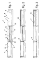
- FIG. 1 In the area of the passage 3 are in FIG. 1 three sliding elements 10, 11 and 12 arranged one behind the other, the bottom side are each supported on a rail 7, 8 and 9.
- a sliding element 10 can be moved as a movable lsolierglasemia on the rail 9
- a middle sliding element 11 may be formed as a fly screen and is movable on the rail 8, while the sliding element 12 is movable as sun protection on the rail 7.
- the sliding elements 10, 11 and 12 may also comprise other elements, in particular photovoltaic elements, insulating elements or protective elements.
- the outermost sliding element 12 (sunshade) has moved into an opening position and is therefore located in the lateral field 5 FIG. 3
- the middle sliding element is moved to the open position, where it accordingly FIG. 4
- FIG. 6 a position is shown in which all the sliding elements 10, 11 and 12 are moved into an opening position, so that the central panel 3 is open with the passage.
- a bottom profile 13 is now arranged on the bottom side, which forms a flat passage.
- the soil profile on a substantially flat surface which is optionally profiled for slip resistance by a few millimeters, but otherwise lies with the adjacent ground plane 17 on a plane.
- the bottom profile 13 is frontally provided with a holder 14 which has three projections 15. Each projection 15 is connected to a coupling portion 16 on one of the sliding elements 10, 11 and 12.
- At least one of the sliding elements 10, 11 or 12 is decoupled from the bottom profile 13 and the bottom profile 13 is arranged in the lateral field 4. Only when all the sliding elements 10, 11 and 12 are moved to an open position, the bottom profile 13 is pulled into the middle panel 3, each the sliding elements 10, 11 or 12 can pull the bottom profile 13 into the passage 3, depending on which coupling element 16 is in engagement with the projection 15 on the strip 14.
- the coupling can be done mechanically via locking elements, but also hydraulically, electrically or magnetically. If one of the sliding elements 10, 11 or 12 is moved into a closed position, the bottom profile 13 moves back into the field 4 at the same time.
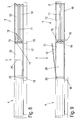
- FIG. 7A Fig. 3 is a sectional view through the passage 3 when all the slide members 10, 11 and 12 are arranged in a closed position.
- the sliding elements 10,11 and 12 are each supported by one or more rollers 20, which roll on a running surface on the rails 7, 8 or 9.
- the rails 7, 8 and 9 are arranged below a ground plane, which is formed by the surface of the adjacent floor panels 17 and 19.
- FIG. 7B is a sectional view through the sliding door system 1 shown, when all the sliding elements 10, 11 and 12 are arranged in an open position, so that the bottom profile 13 is arranged on the passage 3 ( FIG. 6 ).
- the bottom profile 13 is also supported by rollers 20 on the rails 7 and 9, wherein the middle rail 8 can optionally also serve to support the bottom profile 13.
- the bottom profile 13 is formed as a hollow profile, preferably made of aluminum, but may also be made of wood, plastic, steel or other materials. At the top of the bottom profile 13 a slight profiling is incorporated, which forms a slip resistance.
- the top of the bottom profile 13 is at a height with the adjacent floor panels 17 and 19, so that a substantially planar transition between the floor panels 17 and 19 and the bottom profile 13 is formed.
- a further sliding element which may optionally be fixedly connected to the bottom profile 13.
- the sliding element comprises a passage 25 and a fixed element 26, which are spaced apart by a partition wall 27. Thereby, the wide passage of the central panel 3 can be divided, whereby the advantages of the flat floor profile 13 can be further utilized.
- the movement of the sliding elements 10, 11 and 12 and the coupling with the bottom profile 13 is formed as in the previous embodiment.
- FIG. 9 a further alternative of a sliding door system is shown in which above the bottom profile 13, a door member 30 is arranged.
- the door element comprises a pivotable door 31, which is pivotably mounted on a frame profile 32.
- the sliding door system 1 can provide a closable passage 3, at which the advantages of a smooth passage can be used, but also a closure by one or more sliding elements 10, 11 or 12 is possible.
- sliding elements 10, 11 and 12 are shown in each case. It is of course possible to provide even a single sliding element, as guided on a bottom rail. Also, two or more sliding elements may be provided.
Landscapes
- Engineering & Computer Science (AREA)
- Mechanical Engineering (AREA)
- Civil Engineering (AREA)
- Structural Engineering (AREA)
- Wing Frames And Configurations (AREA)
- Support Devices For Sliding Doors (AREA)
Applications Claiming Priority (1)
| Application Number | Priority Date | Filing Date | Title |
|---|---|---|---|
| DE200920013731 DE202009013731U1 (de) | 2009-11-13 | 2009-11-13 | Schiebetüranlage |
Publications (3)
| Publication Number | Publication Date |
|---|---|
| EP2322747A2 true EP2322747A2 (fr) | 2011-05-18 |
| EP2322747A3 EP2322747A3 (fr) | 2013-05-01 |
| EP2322747B1 EP2322747B1 (fr) | 2017-12-27 |
Family
ID=43480931
Family Applications (1)
| Application Number | Title | Priority Date | Filing Date |
|---|---|---|---|
| EP10190673.3A Active EP2322747B1 (fr) | 2009-11-13 | 2010-11-10 | Installation de porte coulissante |
Country Status (3)
| Country | Link |
|---|---|
| EP (1) | EP2322747B1 (fr) |
| DE (1) | DE202009013731U1 (fr) |
| ES (1) | ES2662045T3 (fr) |
Families Citing this family (1)
| Publication number | Priority date | Publication date | Assignee | Title |
|---|---|---|---|---|
| JP6740021B2 (ja) * | 2016-06-16 | 2020-08-12 | 阿部興業株式会社 | 二連式引戸構造 |
Family Cites Families (7)
| Publication number | Priority date | Publication date | Assignee | Title |
|---|---|---|---|---|
| GB191313915A (en) * | 1913-06-16 | 1914-06-16 | Albert Gottschalk | Improvements in or relating to Fluid Pressure Apparatus for Operating and Controlling Doors, Gates or the like. |
| JP4338496B2 (ja) * | 2003-10-28 | 2009-10-07 | 不二サッシ株式会社 | 引戸構造物の下枠の開口部における蓋体構造 |
| US7290371B2 (en) * | 2004-05-26 | 2007-11-06 | Jack Zimmerman | Combined security strut apparatus and threshold cover for sliding doors and windows |
| DE102005035220A1 (de) * | 2004-08-10 | 2006-06-01 | Inge Frey | Schiebeelement |
| DE102005035222A1 (de) * | 2004-08-10 | 2006-02-23 | Inge Frey | Rollenführung |
| FR2911627A1 (fr) * | 2007-01-23 | 2008-07-25 | Bubendorff Sa | Seuil de guidage pour ouvrant coulissant de porte ou de fenetre. |
| SE0700550L (sv) * | 2007-03-07 | 2007-11-13 | Nordiska Balco Ab | Fönsterlucka, därmed försedd skjutfönsteranordning samt balkonginglasning |
-
2009
- 2009-11-13 DE DE200920013731 patent/DE202009013731U1/de not_active Expired - Lifetime
-
2010
- 2010-11-10 ES ES10190673.3T patent/ES2662045T3/es active Active
- 2010-11-10 EP EP10190673.3A patent/EP2322747B1/fr active Active
Non-Patent Citations (1)
| Title |
|---|
| None |
Also Published As
| Publication number | Publication date |
|---|---|
| EP2322747A3 (fr) | 2013-05-01 |
| ES2662045T3 (es) | 2018-04-05 |
| EP2322747B1 (fr) | 2017-12-27 |
| DE202009013731U1 (de) | 2011-03-24 |
Similar Documents
| Publication | Publication Date | Title |
|---|---|---|
| EP3225771A1 (fr) | Seuil de porte pour une porte coulissante et porte coulissante | |
| WO2012156468A1 (fr) | Paroi coulissante comportant au moins un battant | |
| DE102007028473A1 (de) | Schiebetür und Duschabtrennung mit Schiebetür | |
| EP2322747B1 (fr) | Installation de porte coulissante | |
| DE19829783B4 (de) | Schiebetür- oder Trennwandanlage | |
| DE19907242B4 (de) | Mobile Trennwand mit Abschlußprofil | |
| DE202015103771U1 (de) | Verglasungssystem | |
| DE4325698C2 (de) | Nebentür | |
| DE19907232A1 (de) | Mobile Trennwand mit Abschlußprofil | |
| DE102005035220A1 (de) | Schiebeelement | |
| DE2610398A1 (de) | Schiebedach zur ueberdachung von terrassen und aehnlichen flaechen | |
| EP2072744B1 (fr) | Profilés dormants pour une porte coulissante relevable | |
| EP2381056A1 (fr) | Guide de sol pour une porte sectionnelle latérale | |
| DE202007019187U1 (de) | Sektionaltor | |
| DE19751657C2 (de) | Glaswand für Dachgeschoßräume unter einem geneigten Dach | |
| DE102017118275B4 (de) | Torvorrichtung und diese enthaltende Toranordnung | |
| DE102016111410A1 (de) | Mittelstütze für eine Gebäudeöffnung mit großer lichter Breite | |
| EP2669462A1 (fr) | Dispositif de retenue pour stores à lamelles contractées | |
| DE102021115544A1 (de) | Schiebetüranlage | |
| EP3660253B1 (fr) | Système de porte automatique, en particulier sous la forme d'une porte coulissante ou d'une porte coulissante télescopique ou d'une porte pliante, et bâtiment comportant un tel système de porte automatique | |
| DE146723C (fr) | ||
| AT503892B1 (de) | Sektionaltor | |
| DE2619737A1 (de) | Lamellenpanzertor, insbesondere garagentor | |
| AT519518A1 (de) | Abdeckvorrichtung zum Abdecken von Öffnungen | |
| DE3416535A1 (de) | Tonnengewoelbe-ueberdachung aus acrylglas |
Legal Events
| Date | Code | Title | Description |
|---|---|---|---|
| PUAI | Public reference made under article 153(3) epc to a published international application that has entered the european phase |
Free format text: ORIGINAL CODE: 0009012 |
|
| AK | Designated contracting states |
Kind code of ref document: A2 Designated state(s): AL AT BE BG CH CY CZ DE DK EE ES FI FR GB GR HR HU IE IS IT LI LT LU LV MC MK MT NL NO PL PT RO RS SE SI SK SM TR |
|
| AX | Request for extension of the european patent |
Extension state: BA ME |
|
| PUAL | Search report despatched |
Free format text: ORIGINAL CODE: 0009013 |
|
| AK | Designated contracting states |
Kind code of ref document: A3 Designated state(s): AL AT BE BG CH CY CZ DE DK EE ES FI FR GB GR HR HU IE IS IT LI LT LU LV MC MK MT NL NO PL PT RO RS SE SI SK SM TR |
|
| AX | Request for extension of the european patent |
Extension state: BA ME |
|
| RIC1 | Information provided on ipc code assigned before grant |
Ipc: E05D 15/06 20060101ALI20130326BHEP Ipc: E05D 11/08 20060101AFI20130326BHEP Ipc: E05D 15/08 20060101ALN20130326BHEP Ipc: E06B 3/46 20060101ALI20130326BHEP |
|
| RBV | Designated contracting states (corrected) |
Designated state(s): AL AT BE BG CH CY CZ DE DK EE ES FI FR GB GR HR HU IE IS IT LI LT LU LV MC MK MT NL NO PL PT RO RS SE SI SK SM TR |
|
| 17P | Request for examination filed |
Effective date: 20130706 |
|
| 17Q | First examination report despatched |
Effective date: 20160304 |
|
| RIC1 | Information provided on ipc code assigned before grant |
Ipc: E05D 15/06 20060101ALI20170316BHEP Ipc: E05D 15/08 20060101ALN20170316BHEP Ipc: E06B 1/70 20060101ALI20170316BHEP Ipc: E05D 11/08 20060101AFI20170316BHEP Ipc: E06B 3/46 20060101ALI20170316BHEP |
|
| GRAP | Despatch of communication of intention to grant a patent |
Free format text: ORIGINAL CODE: EPIDOSNIGR1 |
|
| INTG | Intention to grant announced |
Effective date: 20170602 |
|
| GRAS | Grant fee paid |
Free format text: ORIGINAL CODE: EPIDOSNIGR3 |
|
| GRAA | (expected) grant |
Free format text: ORIGINAL CODE: 0009210 |
|
| AK | Designated contracting states |
Kind code of ref document: B1 Designated state(s): AL AT BE BG CH CY CZ DE DK EE ES FI FR GB GR HR HU IE IS IT LI LT LU LV MC MK MT NL NO PL PT RO RS SE SI SK SM TR |
|
| REG | Reference to a national code |
Ref country code: GB Ref legal event code: FG4D Free format text: NOT ENGLISH |
|
| REG | Reference to a national code |
Ref country code: CH Ref legal event code: EP |
|
| REG | Reference to a national code |
Ref country code: AT Ref legal event code: REF Ref document number: 958450 Country of ref document: AT Kind code of ref document: T Effective date: 20180115 |
|
| REG | Reference to a national code |
Ref country code: IE Ref legal event code: FG4D Free format text: LANGUAGE OF EP DOCUMENT: GERMAN |
|
| REG | Reference to a national code |
Ref country code: CH Ref legal event code: NV Representative=s name: KATZAROV S.A., CH |
|
| REG | Reference to a national code |
Ref country code: DE Ref legal event code: R096 Ref document number: 502010014503 Country of ref document: DE |
|
| REG | Reference to a national code |
Ref country code: CH Ref legal event code: PCAR Free format text: NEW ADDRESS: AVENUE DES MORGINES 12, 1213 PETIT-LANCY (CH) |
|
| REG | Reference to a national code |
Ref country code: ES Ref legal event code: FG2A Ref document number: 2662045 Country of ref document: ES Kind code of ref document: T3 Effective date: 20180405 |
|
| PG25 | Lapsed in a contracting state [announced via postgrant information from national office to epo] |
Ref country code: NO Free format text: LAPSE BECAUSE OF FAILURE TO SUBMIT A TRANSLATION OF THE DESCRIPTION OR TO PAY THE FEE WITHIN THE PRESCRIBED TIME-LIMIT Effective date: 20180327 Ref country code: FI Free format text: LAPSE BECAUSE OF FAILURE TO SUBMIT A TRANSLATION OF THE DESCRIPTION OR TO PAY THE FEE WITHIN THE PRESCRIBED TIME-LIMIT Effective date: 20171227 Ref country code: LT Free format text: LAPSE BECAUSE OF FAILURE TO SUBMIT A TRANSLATION OF THE DESCRIPTION OR TO PAY THE FEE WITHIN THE PRESCRIBED TIME-LIMIT Effective date: 20171227 |
|
| REG | Reference to a national code |
Ref country code: NL Ref legal event code: MP Effective date: 20171227 |
|
| REG | Reference to a national code |
Ref country code: LT Ref legal event code: MG4D |
|
| PG25 | Lapsed in a contracting state [announced via postgrant information from national office to epo] |
Ref country code: HR Free format text: LAPSE BECAUSE OF FAILURE TO SUBMIT A TRANSLATION OF THE DESCRIPTION OR TO PAY THE FEE WITHIN THE PRESCRIBED TIME-LIMIT Effective date: 20171227 Ref country code: BG Free format text: LAPSE BECAUSE OF FAILURE TO SUBMIT A TRANSLATION OF THE DESCRIPTION OR TO PAY THE FEE WITHIN THE PRESCRIBED TIME-LIMIT Effective date: 20180327 Ref country code: RS Free format text: LAPSE BECAUSE OF FAILURE TO SUBMIT A TRANSLATION OF THE DESCRIPTION OR TO PAY THE FEE WITHIN THE PRESCRIBED TIME-LIMIT Effective date: 20171227 Ref country code: GR Free format text: LAPSE BECAUSE OF FAILURE TO SUBMIT A TRANSLATION OF THE DESCRIPTION OR TO PAY THE FEE WITHIN THE PRESCRIBED TIME-LIMIT Effective date: 20180328 Ref country code: LV Free format text: LAPSE BECAUSE OF FAILURE TO SUBMIT A TRANSLATION OF THE DESCRIPTION OR TO PAY THE FEE WITHIN THE PRESCRIBED TIME-LIMIT Effective date: 20171227 |
|
| PG25 | Lapsed in a contracting state [announced via postgrant information from national office to epo] |
Ref country code: NL Free format text: LAPSE BECAUSE OF FAILURE TO SUBMIT A TRANSLATION OF THE DESCRIPTION OR TO PAY THE FEE WITHIN THE PRESCRIBED TIME-LIMIT Effective date: 20171227 |
|
| PG25 | Lapsed in a contracting state [announced via postgrant information from national office to epo] |
Ref country code: SK Free format text: LAPSE BECAUSE OF FAILURE TO SUBMIT A TRANSLATION OF THE DESCRIPTION OR TO PAY THE FEE WITHIN THE PRESCRIBED TIME-LIMIT Effective date: 20171227 Ref country code: EE Free format text: LAPSE BECAUSE OF FAILURE TO SUBMIT A TRANSLATION OF THE DESCRIPTION OR TO PAY THE FEE WITHIN THE PRESCRIBED TIME-LIMIT Effective date: 20171227 Ref country code: CZ Free format text: LAPSE BECAUSE OF FAILURE TO SUBMIT A TRANSLATION OF THE DESCRIPTION OR TO PAY THE FEE WITHIN THE PRESCRIBED TIME-LIMIT Effective date: 20171227 Ref country code: CY Free format text: LAPSE BECAUSE OF FAILURE TO SUBMIT A TRANSLATION OF THE DESCRIPTION OR TO PAY THE FEE WITHIN THE PRESCRIBED TIME-LIMIT Effective date: 20171227 |
|
| PG25 | Lapsed in a contracting state [announced via postgrant information from national office to epo] |
Ref country code: SM Free format text: LAPSE BECAUSE OF FAILURE TO SUBMIT A TRANSLATION OF THE DESCRIPTION OR TO PAY THE FEE WITHIN THE PRESCRIBED TIME-LIMIT Effective date: 20171227 Ref country code: PL Free format text: LAPSE BECAUSE OF FAILURE TO SUBMIT A TRANSLATION OF THE DESCRIPTION OR TO PAY THE FEE WITHIN THE PRESCRIBED TIME-LIMIT Effective date: 20171227 Ref country code: IS Free format text: LAPSE BECAUSE OF FAILURE TO SUBMIT A TRANSLATION OF THE DESCRIPTION OR TO PAY THE FEE WITHIN THE PRESCRIBED TIME-LIMIT Effective date: 20180427 Ref country code: RO Free format text: LAPSE BECAUSE OF FAILURE TO SUBMIT A TRANSLATION OF THE DESCRIPTION OR TO PAY THE FEE WITHIN THE PRESCRIBED TIME-LIMIT Effective date: 20171227 |
|
| PG25 | Lapsed in a contracting state [announced via postgrant information from national office to epo] |
Ref country code: MT Free format text: LAPSE BECAUSE OF FAILURE TO SUBMIT A TRANSLATION OF THE DESCRIPTION OR TO PAY THE FEE WITHIN THE PRESCRIBED TIME-LIMIT Effective date: 20171227 |
|
| REG | Reference to a national code |
Ref country code: DE Ref legal event code: R097 Ref document number: 502010014503 Country of ref document: DE |
|
| PLBE | No opposition filed within time limit |
Free format text: ORIGINAL CODE: 0009261 |
|
| STAA | Information on the status of an ep patent application or granted ep patent |
Free format text: STATUS: NO OPPOSITION FILED WITHIN TIME LIMIT |
|
| PG25 | Lapsed in a contracting state [announced via postgrant information from national office to epo] |
Ref country code: DK Free format text: LAPSE BECAUSE OF FAILURE TO SUBMIT A TRANSLATION OF THE DESCRIPTION OR TO PAY THE FEE WITHIN THE PRESCRIBED TIME-LIMIT Effective date: 20171227 |
|
| 26N | No opposition filed |
Effective date: 20180928 |
|
| PG25 | Lapsed in a contracting state [announced via postgrant information from national office to epo] |
Ref country code: SI Free format text: LAPSE BECAUSE OF FAILURE TO SUBMIT A TRANSLATION OF THE DESCRIPTION OR TO PAY THE FEE WITHIN THE PRESCRIBED TIME-LIMIT Effective date: 20171227 |
|
| PGFP | Annual fee paid to national office [announced via postgrant information from national office to epo] |
Ref country code: SI Payment date: 20180917 Year of fee payment: 11 |
|
| GBPC | Gb: european patent ceased through non-payment of renewal fee |
Effective date: 20181110 |
|
| PG25 | Lapsed in a contracting state [announced via postgrant information from national office to epo] |
Ref country code: MC Free format text: LAPSE BECAUSE OF FAILURE TO SUBMIT A TRANSLATION OF THE DESCRIPTION OR TO PAY THE FEE WITHIN THE PRESCRIBED TIME-LIMIT Effective date: 20171227 Ref country code: LU Free format text: LAPSE BECAUSE OF NON-PAYMENT OF DUE FEES Effective date: 20181110 |
|
| REG | Reference to a national code |
Ref country code: BE Ref legal event code: MM Effective date: 20181130 |
|
| REG | Reference to a national code |
Ref country code: IE Ref legal event code: MM4A |
|
| PG25 | Lapsed in a contracting state [announced via postgrant information from national office to epo] |
Ref country code: IE Free format text: LAPSE BECAUSE OF NON-PAYMENT OF DUE FEES Effective date: 20181110 |
|
| PG25 | Lapsed in a contracting state [announced via postgrant information from national office to epo] |
Ref country code: BE Free format text: LAPSE BECAUSE OF NON-PAYMENT OF DUE FEES Effective date: 20181130 |
|
| PG25 | Lapsed in a contracting state [announced via postgrant information from national office to epo] |
Ref country code: GB Free format text: LAPSE BECAUSE OF NON-PAYMENT OF DUE FEES Effective date: 20181110 |
|
| PG25 | Lapsed in a contracting state [announced via postgrant information from national office to epo] |
Ref country code: TR Free format text: LAPSE BECAUSE OF FAILURE TO SUBMIT A TRANSLATION OF THE DESCRIPTION OR TO PAY THE FEE WITHIN THE PRESCRIBED TIME-LIMIT Effective date: 20171227 |
|
| PG25 | Lapsed in a contracting state [announced via postgrant information from national office to epo] |
Ref country code: PT Free format text: LAPSE BECAUSE OF FAILURE TO SUBMIT A TRANSLATION OF THE DESCRIPTION OR TO PAY THE FEE WITHIN THE PRESCRIBED TIME-LIMIT Effective date: 20171227 |
|
| PG25 | Lapsed in a contracting state [announced via postgrant information from national office to epo] |
Ref country code: SE Free format text: LAPSE BECAUSE OF FAILURE TO SUBMIT A TRANSLATION OF THE DESCRIPTION OR TO PAY THE FEE WITHIN THE PRESCRIBED TIME-LIMIT Effective date: 20171227 Ref country code: HU Free format text: LAPSE BECAUSE OF FAILURE TO SUBMIT A TRANSLATION OF THE DESCRIPTION OR TO PAY THE FEE WITHIN THE PRESCRIBED TIME-LIMIT; INVALID AB INITIO Effective date: 20101110 Ref country code: MK Free format text: LAPSE BECAUSE OF NON-PAYMENT OF DUE FEES Effective date: 20171227 |
|
| PG25 | Lapsed in a contracting state [announced via postgrant information from national office to epo] |
Ref country code: AL Free format text: LAPSE BECAUSE OF FAILURE TO SUBMIT A TRANSLATION OF THE DESCRIPTION OR TO PAY THE FEE WITHIN THE PRESCRIBED TIME-LIMIT Effective date: 20171227 |
|
| PGFP | Annual fee paid to national office [announced via postgrant information from national office to epo] |
Ref country code: AT Payment date: 20201027 Year of fee payment: 11 Ref country code: IT Payment date: 20201130 Year of fee payment: 11 Ref country code: FR Payment date: 20201022 Year of fee payment: 11 Ref country code: CH Payment date: 20201022 Year of fee payment: 11 |
|
| REG | Reference to a national code |
Ref country code: ES Ref legal event code: FD2A Effective date: 20210531 |
|
| PG25 | Lapsed in a contracting state [announced via postgrant information from national office to epo] |
Ref country code: ES Free format text: LAPSE BECAUSE OF NON-PAYMENT OF DUE FEES Effective date: 20191111 |
|
| REG | Reference to a national code |
Ref country code: CH Ref legal event code: PL |
|
| REG | Reference to a national code |
Ref country code: AT Ref legal event code: MM01 Ref document number: 958450 Country of ref document: AT Kind code of ref document: T Effective date: 20211110 |
|
| PG25 | Lapsed in a contracting state [announced via postgrant information from national office to epo] |
Ref country code: LI Free format text: LAPSE BECAUSE OF NON-PAYMENT OF DUE FEES Effective date: 20211130 Ref country code: CH Free format text: LAPSE BECAUSE OF NON-PAYMENT OF DUE FEES Effective date: 20211130 Ref country code: AT Free format text: LAPSE BECAUSE OF NON-PAYMENT OF DUE FEES Effective date: 20211110 |
|
| PG25 | Lapsed in a contracting state [announced via postgrant information from national office to epo] |
Ref country code: FR Free format text: LAPSE BECAUSE OF NON-PAYMENT OF DUE FEES Effective date: 20211130 |
|
| PG25 | Lapsed in a contracting state [announced via postgrant information from national office to epo] |
Ref country code: IT Free format text: LAPSE BECAUSE OF NON-PAYMENT OF DUE FEES Effective date: 20211110 |
|
| P01 | Opt-out of the competence of the unified patent court (upc) registered |
Effective date: 20230813 |
|
| PGFP | Annual fee paid to national office [announced via postgrant information from national office to epo] |
Ref country code: DE Payment date: 20241107 Year of fee payment: 15 |