EP2322770A1 - Zeitgeber für ventilöffnung und -schliessung - Google Patents
Zeitgeber für ventilöffnung und -schliessung Download PDFInfo
- Publication number
- EP2322770A1 EP2322770A1 EP10755783A EP10755783A EP2322770A1 EP 2322770 A1 EP2322770 A1 EP 2322770A1 EP 10755783 A EP10755783 A EP 10755783A EP 10755783 A EP10755783 A EP 10755783A EP 2322770 A1 EP2322770 A1 EP 2322770A1
- Authority
- EP
- European Patent Office
- Prior art keywords
- fluid
- switching valve
- passageway
- valve
- feeding
- Prior art date
- Legal status (The legal status is an assumption and is not a legal conclusion. Google has not performed a legal analysis and makes no representation as to the accuracy of the status listed.)
- Granted
Links
- 239000012530 fluid Substances 0.000 claims abstract description 103
- 238000007599 discharging Methods 0.000 claims abstract description 25
- 230000002401 inhibitory effect Effects 0.000 claims abstract description 3
- 238000002485 combustion reaction Methods 0.000 claims description 15
- 238000000638 solvent extraction Methods 0.000 claims description 4
- 230000000694 effects Effects 0.000 abstract description 4
- 238000010276 construction Methods 0.000 description 6
- 238000010586 diagram Methods 0.000 description 5
- 238000006073 displacement reaction Methods 0.000 description 3
- 230000002093 peripheral effect Effects 0.000 description 3
- 230000010349 pulsation Effects 0.000 description 2
- 230000007704 transition Effects 0.000 description 2
- 230000006835 compression Effects 0.000 description 1
- 238000007906 compression Methods 0.000 description 1
- 230000003247 decreasing effect Effects 0.000 description 1
Images


Classifications
-
- F—MECHANICAL ENGINEERING; LIGHTING; HEATING; WEAPONS; BLASTING
- F01—MACHINES OR ENGINES IN GENERAL; ENGINE PLANTS IN GENERAL; STEAM ENGINES
- F01L—CYCLICALLY OPERATING VALVES FOR MACHINES OR ENGINES
- F01L1/00—Valve-gear or valve arrangements, e.g. lift-valve gear
- F01L1/34—Valve-gear or valve arrangements, e.g. lift-valve gear characterised by the provision of means for changing the timing of the valves without changing the duration of opening and without affecting the magnitude of the valve lift
- F01L1/344—Valve-gear or valve arrangements, e.g. lift-valve gear characterised by the provision of means for changing the timing of the valves without changing the duration of opening and without affecting the magnitude of the valve lift changing the angular relationship between crankshaft and camshaft, e.g. using helicoidal gear
- F01L1/3442—Valve-gear or valve arrangements, e.g. lift-valve gear characterised by the provision of means for changing the timing of the valves without changing the duration of opening and without affecting the magnitude of the valve lift changing the angular relationship between crankshaft and camshaft, e.g. using helicoidal gear using hydraulic chambers with variable volume to transmit the rotating force
-
- F—MECHANICAL ENGINEERING; LIGHTING; HEATING; WEAPONS; BLASTING
- F01—MACHINES OR ENGINES IN GENERAL; ENGINE PLANTS IN GENERAL; STEAM ENGINES
- F01L—CYCLICALLY OPERATING VALVES FOR MACHINES OR ENGINES
- F01L1/00—Valve-gear or valve arrangements, e.g. lift-valve gear
- F01L1/02—Valve drive
- F01L1/022—Chain drive
-
- F—MECHANICAL ENGINEERING; LIGHTING; HEATING; WEAPONS; BLASTING
- F01—MACHINES OR ENGINES IN GENERAL; ENGINE PLANTS IN GENERAL; STEAM ENGINES
- F01L—CYCLICALLY OPERATING VALVES FOR MACHINES OR ENGINES
- F01L1/00—Valve-gear or valve arrangements, e.g. lift-valve gear
- F01L1/34—Valve-gear or valve arrangements, e.g. lift-valve gear characterised by the provision of means for changing the timing of the valves without changing the duration of opening and without affecting the magnitude of the valve lift
- F01L1/344—Valve-gear or valve arrangements, e.g. lift-valve gear characterised by the provision of means for changing the timing of the valves without changing the duration of opening and without affecting the magnitude of the valve lift changing the angular relationship between crankshaft and camshaft, e.g. using helicoidal gear
- F01L1/3442—Valve-gear or valve arrangements, e.g. lift-valve gear characterised by the provision of means for changing the timing of the valves without changing the duration of opening and without affecting the magnitude of the valve lift changing the angular relationship between crankshaft and camshaft, e.g. using helicoidal gear using hydraulic chambers with variable volume to transmit the rotating force
- F01L2001/34423—Details relating to the hydraulic feeding circuit
- F01L2001/34426—Oil control valves
-
- F—MECHANICAL ENGINEERING; LIGHTING; HEATING; WEAPONS; BLASTING
- F01—MACHINES OR ENGINES IN GENERAL; ENGINE PLANTS IN GENERAL; STEAM ENGINES
- F01L—CYCLICALLY OPERATING VALVES FOR MACHINES OR ENGINES
- F01L1/00—Valve-gear or valve arrangements, e.g. lift-valve gear
- F01L1/34—Valve-gear or valve arrangements, e.g. lift-valve gear characterised by the provision of means for changing the timing of the valves without changing the duration of opening and without affecting the magnitude of the valve lift
- F01L1/344—Valve-gear or valve arrangements, e.g. lift-valve gear characterised by the provision of means for changing the timing of the valves without changing the duration of opening and without affecting the magnitude of the valve lift changing the angular relationship between crankshaft and camshaft, e.g. using helicoidal gear
- F01L1/3442—Valve-gear or valve arrangements, e.g. lift-valve gear characterised by the provision of means for changing the timing of the valves without changing the duration of opening and without affecting the magnitude of the valve lift changing the angular relationship between crankshaft and camshaft, e.g. using helicoidal gear using hydraulic chambers with variable volume to transmit the rotating force
- F01L2001/34423—Details relating to the hydraulic feeding circuit
- F01L2001/34426—Oil control valves
- F01L2001/3443—Solenoid driven oil control valves
-
- F—MECHANICAL ENGINEERING; LIGHTING; HEATING; WEAPONS; BLASTING
- F01—MACHINES OR ENGINES IN GENERAL; ENGINE PLANTS IN GENERAL; STEAM ENGINES
- F01L—CYCLICALLY OPERATING VALVES FOR MACHINES OR ENGINES
- F01L1/00—Valve-gear or valve arrangements, e.g. lift-valve gear
- F01L1/34—Valve-gear or valve arrangements, e.g. lift-valve gear characterised by the provision of means for changing the timing of the valves without changing the duration of opening and without affecting the magnitude of the valve lift
- F01L1/344—Valve-gear or valve arrangements, e.g. lift-valve gear characterised by the provision of means for changing the timing of the valves without changing the duration of opening and without affecting the magnitude of the valve lift changing the angular relationship between crankshaft and camshaft, e.g. using helicoidal gear
- F01L1/3442—Valve-gear or valve arrangements, e.g. lift-valve gear characterised by the provision of means for changing the timing of the valves without changing the duration of opening and without affecting the magnitude of the valve lift changing the angular relationship between crankshaft and camshaft, e.g. using helicoidal gear using hydraulic chambers with variable volume to transmit the rotating force
- F01L2001/3445—Details relating to the hydraulic means for changing the angular relationship
- F01L2001/34453—Locking means between driving and driven members
- F01L2001/34463—Locking position intermediate between most retarded and most advanced positions
-
- F—MECHANICAL ENGINEERING; LIGHTING; HEATING; WEAPONS; BLASTING
- F01—MACHINES OR ENGINES IN GENERAL; ENGINE PLANTS IN GENERAL; STEAM ENGINES
- F01L—CYCLICALLY OPERATING VALVES FOR MACHINES OR ENGINES
- F01L1/00—Valve-gear or valve arrangements, e.g. lift-valve gear
- F01L1/34—Valve-gear or valve arrangements, e.g. lift-valve gear characterised by the provision of means for changing the timing of the valves without changing the duration of opening and without affecting the magnitude of the valve lift
- F01L1/344—Valve-gear or valve arrangements, e.g. lift-valve gear characterised by the provision of means for changing the timing of the valves without changing the duration of opening and without affecting the magnitude of the valve lift changing the angular relationship between crankshaft and camshaft, e.g. using helicoidal gear
- F01L1/3442—Valve-gear or valve arrangements, e.g. lift-valve gear characterised by the provision of means for changing the timing of the valves without changing the duration of opening and without affecting the magnitude of the valve lift changing the angular relationship between crankshaft and camshaft, e.g. using helicoidal gear using hydraulic chambers with variable volume to transmit the rotating force
- F01L2001/3445—Details relating to the hydraulic means for changing the angular relationship
- F01L2001/34453—Locking means between driving and driven members
- F01L2001/34466—Locking means between driving and driven members with multiple locking devices
-
- F—MECHANICAL ENGINEERING; LIGHTING; HEATING; WEAPONS; BLASTING
- F01—MACHINES OR ENGINES IN GENERAL; ENGINE PLANTS IN GENERAL; STEAM ENGINES
- F01L—CYCLICALLY OPERATING VALVES FOR MACHINES OR ENGINES
- F01L1/00—Valve-gear or valve arrangements, e.g. lift-valve gear
- F01L1/34—Valve-gear or valve arrangements, e.g. lift-valve gear characterised by the provision of means for changing the timing of the valves without changing the duration of opening and without affecting the magnitude of the valve lift
- F01L1/344—Valve-gear or valve arrangements, e.g. lift-valve gear characterised by the provision of means for changing the timing of the valves without changing the duration of opening and without affecting the magnitude of the valve lift changing the angular relationship between crankshaft and camshaft, e.g. using helicoidal gear
- F01L1/3442—Valve-gear or valve arrangements, e.g. lift-valve gear characterised by the provision of means for changing the timing of the valves without changing the duration of opening and without affecting the magnitude of the valve lift changing the angular relationship between crankshaft and camshaft, e.g. using helicoidal gear using hydraulic chambers with variable volume to transmit the rotating force
- F01L2001/3445—Details relating to the hydraulic means for changing the angular relationship
- F01L2001/34453—Locking means between driving and driven members
- F01L2001/34473—Lock movement perpendicular to camshaft axis
-
- F—MECHANICAL ENGINEERING; LIGHTING; HEATING; WEAPONS; BLASTING
- F01—MACHINES OR ENGINES IN GENERAL; ENGINE PLANTS IN GENERAL; STEAM ENGINES
- F01L—CYCLICALLY OPERATING VALVES FOR MACHINES OR ENGINES
- F01L1/00—Valve-gear or valve arrangements, e.g. lift-valve gear
- F01L1/34—Valve-gear or valve arrangements, e.g. lift-valve gear characterised by the provision of means for changing the timing of the valves without changing the duration of opening and without affecting the magnitude of the valve lift
- F01L1/344—Valve-gear or valve arrangements, e.g. lift-valve gear characterised by the provision of means for changing the timing of the valves without changing the duration of opening and without affecting the magnitude of the valve lift changing the angular relationship between crankshaft and camshaft, e.g. using helicoidal gear
- F01L1/3442—Valve-gear or valve arrangements, e.g. lift-valve gear characterised by the provision of means for changing the timing of the valves without changing the duration of opening and without affecting the magnitude of the valve lift changing the angular relationship between crankshaft and camshaft, e.g. using helicoidal gear using hydraulic chambers with variable volume to transmit the rotating force
- F01L2001/3445—Details relating to the hydraulic means for changing the angular relationship
- F01L2001/34453—Locking means between driving and driven members
- F01L2001/34476—Restrict range locking means
Definitions
- the present invention relates to a valve timing control apparatus used for controlling opening/closing timing of an exhaust valve or an intake value in a valve operated device of an internal combustion engine.
- an apparatus including a rotation transmitting member rotatably mounted on a valve opening/closing rotational shaft to be rotatable relative thereto over a predetermined range and receiving a rotational drive force from a crank pulley, a vane mounted on a rotational shaft comprised of a cam shaft and an inner rotor provided integrally therewith, a fluid pressure chamber formed between the rotational shaft and the rotation transmitting member and divided into an advanced angle chamber and a retarded angle chamber, a first fluid passageway for feeding/discharging fluid to/from the advanced angle chamber, a second fluid passageway for feeding/discharging fluid to/from the retarded angle chamber, a retracting hole formed in the rotation transmitting member for receiving therein a lock pin urged toward the rotational shaft, a receiving hole formed in the rotational shaft for receiving the head of the lock pin when the rotational shaft and the rotation transmitting member come into a predetermined phase synchronization or registry with each other, and
- Patent Document 1 provides a first switching valve for controlling feeding/discharging of the fluid to/from the first fluid passageway and the second fluid passageway and a second switching valve for controlling feeding/discharging of the fluid to/from the third fluid passageway, so that the feeding/discharging of the fluid to/from the third fluid passageway may take place independently of the feeding/discharging of the fluid to/from the first and second fluid passageways.
- Patent Document 1 Japanese Patent Application "Kokai" No. 10-220207
- Pulsating displacements due to such torque variations described above will occur conspicuously in particular when the pressure of the fluid fed from the pump is low. And, this phenomenon occurs also in the course of switchover of the phase of the cam shaft relative to the crank shaft to a target phase on the retarded angle side from the advanced angle side.
- a pressure drop due to the pulsating pressure may lower a lock released state maintaining pressure of the lock mechanism, as a result of which the locking mechanism may be brought into its locking state inadvertently.
- a lock pin provided as a restricting member for the locking mechanism pivots about the outer periphery of a receiving hole while this lock pin is being accommodated within a retracting hole.
- the object of the present invention is to provide a valve timing control apparatus capable of avoiding inadvertent realization of a locked state by effectively preventing pulsating pressure of fluid generated in association with torque variation of a cam shaft from having any effect on a fluid passageway for lock releasing, thereby to restrict occurrence of inadvertent realization of the locked state during driving of the internal combustion engine.
- the apparatus comprises:
- a check valve that inhibits communication of the fluid from the first switching valve to the second switching valve and allows communication of the fluid from the second switching valve to the first switching valve. Therefore, it is possible to prevent pulsating pressure that occurs in association with torque variation in the rotational shaft from being transmitted from the first switching valve to the second switching valve. Hence, stable fluid free from the influence of the pulsating pressure can be fed from the second switching valve to the third fluid passageway. As a result, the locking mechanism can effectively maintain its lock-released state by this stable fluid pressure and the inadvertent locking of the mechanism can be avoided.
- the fluid fed from said pump can be fed to said first switching valve with bypassing said second switching valve and can be fed to said second switching valve with bypassing said first switching valve.
- passage resistance of the first switching valve and the passage resistance of the second switching valve do not affect each other. Hence, controlling operation of rotational phase and controlling operations of the locking mechanism can be effected more speedily.
- the fluid fed from said pump can be fed to said first switching valve through said check valve and can be fed to said second switching valve with bypassing said check valve.
- the check valve is interposed between the pump and the first switching valve, it is possible to prevent pulsating pressure of the fluid occurring due to torque variation in the rotational shaft from being transmitted to the pump. Therefore, the pulsating pressure will not affect the second switching valve via the pump. As a result, the locking mechanism can effectively maintain its lock-released state by this even more stable fluid pressure.
- the apparatus further comprises:
- passage resistance of the first switching valve and the passage resistance of the second switching valve do not affect each other.
- controlling operation of rotational phase and controlling operations of the locking mechanism can be effected more speedily.
- the pulsating pressure does not affect the second switching valve via the pump.
- the locking mechanism can effectively maintain its lock-released state by this even more stable fluid pressure.
- an aperture area of said check valve when the fluid is being fed from said pump to said first switching valve is greater than a passageway aperture area of said first connecting passageway.
- the passageway aperture area of said first connecting passageway is greater than the passageway aperture area of said second connecting passageway.
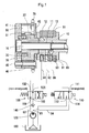
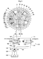
- a valve timing control apparatus of the invention shown in Fig. 1 and Fig. 2 includes a driven rotational body consisting essentially of a cam shaft ("rotational shaft") 10, an inner rotor 30 and vanes (partitioning portions) 50 attached to the inner rotor 30, and a driving rotational body consisting essentially of an outer rotor 40 rotatably mounted on the driven rotational body to be rotatable relative thereto over a predetermined range, lock plates 60a, 60b, a timing sprocket 70, etc.
- the outer periphery of the cam shaft 10 is rotatably supported by a cylinder head 81.
- the timing sprocket 70 is configured to receive a rotational force in the clockwise direction in Fig. 2 from a crank shaft (not shown) via a timing chain (not shown).
- the cam shaft 10 includes a cam (not shown) which per se is well known, for opening/closing an intake valve (not shown) or an exhaust valve (not shown).
- a cam (not shown) which per se is well known, for opening/closing an intake valve (not shown) or an exhaust valve (not shown).
- Fig. 1 and Fig. 2 inside the cam shaft 10, there are formed an advanced angle passageway 11, a retarded angle passageway 12 and a pilot passageway 13 extending along the axial direction.
- the advanced angle passageway 11 is formed within an attaching hole for an attaching bolt 16 provided in the cam shaft 10, and this passageway 11 is connected to a connection port 101 of a first switching valve 100 via an annular passageway 91 and a connecting passageway 92 provided on the outer peripheral side of the supported portion of the cam shaft 10.
- the retarded angle passageway 12 is connected to a connection port 102 of the first switching valve 100 via an annular passageway 93 and a connecting passageway 94 also provided on the outer peripheral side of the supported portion of the cam shaft 10.
- the pilot passageway 13 is connected to a connection port 111 of a second switching valve 110 via an annular passageway 95 and a connecting passageway 96 also provided on the outer peripheral side of the supported portion of the cam shaft 10.
- the first switching valve 100 is controlled for its switching operations by a controller (not shown). Under the condition shown in Fig. 1 and Fig. 2 wherein the valve 100 is switched to an angle advanced position (energized state), a supply port 103 connected to an oil pump 120 via a check valve 140 is connected and communicated to the connection port 101 and also the connection port 102 is connected and communicated to an exhaust port 104 connected to an oil pan 130. Further, under the condition (non-energization) wherein the valve 100 is switched to the most retarded angle position shown on the right hand in the figure, the supply port 103 is connected and communicated to the connection portion 102 and also the connection port 101 is connected and communicated to the exhaust port 104.
- an amount of oil is fed from the oil pump 120 via the check valve 140 to the advanced angle passageway 11 and also an amount of oil is discharged from the retarded angle passageway 12 to the oil pan 130.
- an amount of oil is fed from the oil pump 120 via the check valve 140 to the retarded angle passageway 12 and also an amount of oil is discharged from the advanced angle passageway 11 to the oil pan 130.
- the second switching valve 110 is controlled for its switching operations by the controller (not shown). Under the condition shown in Fig. 1 wherein the valve 110 is switched to the feeding position (energized state), the connection port 111 is connected and communicated to the supply port 114 connected to the oil pump 120 and at the same time, its communication to an exhaust port 113 connected to the oil pan 130 is blocked. Further, under the condition shown in Fig. 2 wherein the valve 110 is switched to the exhausting position (non-energized state), the connection port 111 is connected and communicated to the exhaust port 113 whereas the supply port 114 is blocked. Therefore, under this supplying position condition, oil is supplied to the pilot passageway 13 and under the exhausting position condition, oil is discharged through the pilot passageway 13 to the oil pan 130.
- the inner rotor 30 is fixedly and integrally attached to the cam shaft 10 by the bolt 16 and includes vane grooves 31 for allowing attachment of the four respective vanes 50 along the radial direction. Further, the inner rotor 30 includes also a receiving groove 32, a connecting passageway 33 connecting the bottom of the receiving groove 32 to the pilot passageway 13, a connecting passageway 34 connecting an advanced angle chamber R1 sectioned by each vane 50 and the advanced angle passageway 11 and a connecting passageway 37 connecting a retarded angle chamber R2 sectioned by each vane 50 and the retarded angle passageway 12. Incidentally, each vane 50 is urged in the radially outward direction by means of a spring 51 mounted on the bottom of the vane groove 31.
- the receiving groove 32 is a groove for receiving a head of the lock plate 60a, 60b by a predetermined engagement amount under the condition shown in Fig. 2 , i.e. the condition wherein the relative phases of the driven rotational body such as the cam shaft 10, the inner rotor 30, etc. and the driving rotational body such as the outer rotor 40, the timing sprocket 70, etc. come into synchronization or registry with each other at a predetermined phase (an intermediate phase between the most advanced angle phase and the most retarded angle phase suitable for startup of the internal combustion engine).
- a predetermined phase an intermediate phase between the most advanced angle phase and the most retarded angle phase suitable for startup of the internal combustion engine.
- the outer rotor 40 is assembled to the outer periphery of the inner rotor 30 to be rotatable relative thereto over a predetermined range. And, on opposed sides of the outer rotor 40, a front plate 41 and a rear plate 42 are integrally fastened by means of a bolt 43. Further, in the outer rotor 40, there are formed, by the inner rotor 30, a plurality of operational chambers R0 each of which accommodates the vane 50 corresponding thereto and which is divided into an advanced angle chamber R1 and a retarded angle chamber R2.
- retracting grooves 46a, 46b for accommodating the lock plates 60a, 60b and springs 61a, 61b for urging these plates 60a, 60b toward the inner rotor 30.
- the lock plates 60a, 60b are engaged in the retracting grooves 46a, 46b to be movable along the radial direction of the outer rotor 40 and are urged by the springs 61a, 61b toward the inner rotor 30.
- the springs 61a, 61b are compression springs interposed between the lock plates 60a, 60b and retainers 62a, 62b and these retainers 62a, 62b are fixedly assembled to the outer rotor 40.
- the engine is started up under the condition shown in Fig. 2 , that is, the condition wherein the heads of the lock plates 60a, 60b are engaged and locked within the receiving grooves 32 at a predetermined phase suitable for startup of the internal combustion engine.
- the oil pump 120 is driven to start feeding of an amount of oil.
- the oil discharged from the oil pump 120 is supplied via the check valve 140 from the supply port 103 of the first switching valve 100 through the connection port 101, the connecting passageway 92, the annular passageway 91, the advanced angle passageway 11, the connecting passageway 34 to the advanced angle chamber R1.
- an amount of oil fed from the oil pump 120 to the second switching valve 110 is not supplied to the pilot passageway 13 because the supply port 114 of the second switching valve 110 is currently blocked, so a locking state is maintained.
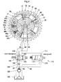
- the first switching valve 100 is energized by a signal from the controller (not shown), as shown in Fig. 5 , the amount of oil discharged from the oil pump 120 is supplied via the check valve 140 from the supply port 103 of the first switching valve 100 through the connection port 102, the connecting passageway 94, the annular passageway 93, the retarded angle passageway 12 and the connecting passageway 37 to the retarded angle chamber R2.
- an amount of oil is discharged from the advanced angle chamber R1 through the advanced angle passageway 11, the switching valve 100, etc. into the oil pan 130.
- the driven rotational body including the cam shaft 10, the inner rotor 30 and the vanes 50, etc.
- Fig. 5 i.e. the condition of the most retarded angle wherein the volume of the advanced angle chamber R1 is rendered minimum.
- the valve opening/closing timing is controlled to an optimal phase as shuttling between the most advanced angle state and the most retarded angle state.
- the condition of the lock plate 60a accommodated in the retracting groove 46a is maintained.
- the condition of the lock plate 60b accommodated in the retracting groove 46b needs to be maintained.
- the check valve 140 which allows communication of oil to the first switching valve 100 and inhibits (checks) communication of oil to the oil pump 120.
- the second switching valve 110 for controlling feeding/discharging of oil to/from the pilot passageway 13 is connected to the oil pump 120 via the second connecting passageway 84 branched from a branching point 83 of the first connecting passageway 82 connecting between the oil pump 120 and the check valve 140.
- the check valve 140 pulsating pressure of oil that occurs due to torque variation in the cam shaft 10 can be prevented from being transmitted from the first switching valve 100 to the oil pump 120.
- the second switching valve 110 is supplied with oil through the second connecting passageway 84 branched from the first connecting passageway 82 connecting between the oil pump 120 and the check valve 140, the second switching valve 110 is free from any effect of the pulsating pressure of oil that occurs due to torque variation in the cam shaft 10. So that, the oil can be supplied in a stable manner from this second switching valve 110 to the pilot passageway 13. As a result, the stable oil can be supplied to the receiving groove 32, so that the condition of the lock plates 60a, 60b being accommodated within the retracting grooves 46a, 46b can be maintained, thereby to prevent occurrence of inadvertent locking.
- the aperture area of the check valve 140 be greater than the passageway aperture area of the first connecting passageway 82. Further, for preferential supply of oil to the operational chamber R0 during the advanced/retarded angle control operations, it is preferred that the passageway aperture area of the first connecting passageway 82 be greater than the passageway aperture area of the second connecting passageway 84.
- the predetermined phase being an intermediate phase between the most advanced angle phase and the most retarded angle phase suitable for startup of the internal combustion engine.
- the invention is not limited thereto. Instead, the "predetermined phase” can be the most retarded angle phase or the most advanced angle phase, as a matter of course.
- the present invention is applicable to a valve timing control apparatus used for controlling opening/closing timing of an exhaust valve or an intake value in a valving device of an internal combustion engine.
Landscapes
- Engineering & Computer Science (AREA)
- Mechanical Engineering (AREA)
- General Engineering & Computer Science (AREA)
- Valve Device For Special Equipments (AREA)
Applications Claiming Priority (2)
| Application Number | Priority Date | Filing Date | Title |
|---|---|---|---|
| JP2009074114A JP2010223172A (ja) | 2009-03-25 | 2009-03-25 | 弁開閉時期制御装置 |
| PCT/JP2010/052267 WO2010109982A1 (ja) | 2009-03-25 | 2010-02-16 | 弁開閉時期制御装置 |
Publications (3)
| Publication Number | Publication Date |
|---|---|
| EP2322770A1 true EP2322770A1 (de) | 2011-05-18 |
| EP2322770A4 EP2322770A4 (de) | 2012-01-11 |
| EP2322770B1 EP2322770B1 (de) | 2013-05-01 |
Family
ID=42780678
Family Applications (1)
| Application Number | Title | Priority Date | Filing Date |
|---|---|---|---|
| EP10755783.7A Not-in-force EP2322770B1 (de) | 2009-03-25 | 2010-02-16 | Zeitgeber für ventilöffnung und -schliessung |
Country Status (5)
| Country | Link |
|---|---|
| US (1) | US20110162606A1 (de) |
| EP (1) | EP2322770B1 (de) |
| JP (1) | JP2010223172A (de) |
| CN (1) | CN102165147B (de) |
| WO (1) | WO2010109982A1 (de) |
Cited By (4)
| Publication number | Priority date | Publication date | Assignee | Title |
|---|---|---|---|---|
| WO2013064261A1 (en) * | 2011-11-02 | 2013-05-10 | Schaeffler Technologies AG & Co. KG | Camshaft adjustment mechanism having a locking apparatus |
| EP2636858A1 (de) * | 2012-03-08 | 2013-09-11 | Aisin Seiki Kabushiki Kaisha | Vorrichtung zur Regelung der variablen Ventilsteuerzeit |
| EP2708707A3 (de) * | 2012-09-18 | 2015-07-29 | Aisin Seiki Kabushiki Kaisha | Steuerungsvorrichtung der Öffnungs- und Schließzeit eines Ventils |
| EP2899377A1 (de) * | 2013-07-30 | 2015-07-29 | Aisin Seiki Kabushiki Kaisha | Variable Ventilsteuerzeit-Steuervorrichtung |
Families Citing this family (11)
| Publication number | Priority date | Publication date | Assignee | Title |
|---|---|---|---|---|
| JP2011236781A (ja) * | 2010-05-07 | 2011-11-24 | Aisin Seiki Co Ltd | 弁開閉時期制御装置 |
| KR101278382B1 (ko) * | 2010-11-08 | 2013-06-24 | 도요타 지도샤(주) | 유압식 밸브 타이밍 가변 기구의 제어 장치 |
| WO2012137336A1 (ja) | 2011-04-07 | 2012-10-11 | トヨタ自動車 株式会社 | バルブタイミング可変装置 |
| US9200543B2 (en) | 2011-05-13 | 2015-12-01 | Toyota Jidosha Kabushiki Kaisha | Variable valve timing device |
| JP5928158B2 (ja) | 2012-05-25 | 2016-06-01 | アイシン精機株式会社 | 弁開閉時期制御装置 |
| CN103485853B (zh) * | 2012-06-13 | 2016-12-28 | 日立汽车系统株式会社 | 内燃机的可变气门装置 |
| JP5839239B2 (ja) * | 2013-05-14 | 2016-01-06 | 株式会社デンソー | バルブタイミング調整装置 |
| WO2014192355A1 (ja) | 2013-05-30 | 2014-12-04 | アイシン精機株式会社 | 弁開閉時期制御装置 |
| JP6183094B2 (ja) * | 2013-09-19 | 2017-08-23 | アイシン精機株式会社 | 弁開閉時期制御ユニット |
| JP2017008791A (ja) * | 2015-06-19 | 2017-01-12 | アイシン精機株式会社 | 弁開閉時期制御装置 |
| US10865666B2 (en) * | 2018-11-05 | 2020-12-15 | Borgwarner Inc. | Check valve for exhausting flow of fluid from a variable cam timing phaser |
Family Cites Families (12)
| Publication number | Priority date | Publication date | Assignee | Title |
|---|---|---|---|---|
| JP4202440B2 (ja) * | 1997-02-06 | 2008-12-24 | アイシン精機株式会社 | 弁開閉時期制御装置 |
| US6510824B2 (en) * | 1997-12-11 | 2003-01-28 | Diesel Engine Retarders, Inc. | Variable lost motion valve actuator and method |
| DE19756016A1 (de) * | 1997-12-17 | 1999-06-24 | Porsche Ag | Vorrichtung zur hydraulischen Drehwinkelverstellung einer Welle zu einem Antriebsrad |
| JP3918971B2 (ja) * | 1998-04-27 | 2007-05-23 | アイシン精機株式会社 | 弁開閉時期制御装置 |
| US6311655B1 (en) * | 2000-01-21 | 2001-11-06 | Borgwarner Inc. | Multi-position variable cam timing system having a vane-mounted locking-piston device |
| JP4001070B2 (ja) * | 2003-07-22 | 2007-10-31 | アイシン精機株式会社 | 弁開閉時期制御装置 |
| JP4145563B2 (ja) * | 2002-05-09 | 2008-09-03 | 株式会社日本自動車部品総合研究所 | バルブタイミング調整装置 |
| JP4214972B2 (ja) * | 2003-08-28 | 2009-01-28 | アイシン精機株式会社 | 弁開閉時期制御装置 |
| JP2006144766A (ja) * | 2004-10-20 | 2006-06-08 | Aisin Seiki Co Ltd | 弁開閉時期制御装置 |
| JP4534147B2 (ja) * | 2005-03-22 | 2010-09-01 | アイシン精機株式会社 | オイル供給装置 |
| DE102005023228B4 (de) * | 2005-05-20 | 2017-09-07 | Schaeffler Technologies AG & Co. KG | Vorrichtung zur variablen Einstellung der Steuerzeiten von Gaswechselventilen einer Brennkraftmaschine |
| JP2008069649A (ja) * | 2006-09-12 | 2008-03-27 | Denso Corp | バルブタイミング調整装置 |
-
2009
- 2009-03-25 JP JP2009074114A patent/JP2010223172A/ja active Pending
-
2010
- 2010-02-16 US US13/063,877 patent/US20110162606A1/en not_active Abandoned
- 2010-02-16 CN CN2010800027080A patent/CN102165147B/zh not_active Expired - Fee Related
- 2010-02-16 WO PCT/JP2010/052267 patent/WO2010109982A1/ja not_active Ceased
- 2010-02-16 EP EP10755783.7A patent/EP2322770B1/de not_active Not-in-force
Cited By (8)
| Publication number | Priority date | Publication date | Assignee | Title |
|---|---|---|---|---|
| WO2013064261A1 (en) * | 2011-11-02 | 2013-05-10 | Schaeffler Technologies AG & Co. KG | Camshaft adjustment mechanism having a locking apparatus |
| EP2636858A1 (de) * | 2012-03-08 | 2013-09-11 | Aisin Seiki Kabushiki Kaisha | Vorrichtung zur Regelung der variablen Ventilsteuerzeit |
| CN103306769A (zh) * | 2012-03-08 | 2013-09-18 | 爱信精机株式会社 | 可变气门正时控制装置 |
| US8776748B2 (en) | 2012-03-08 | 2014-07-15 | Aisin Seiki Kabushiki Kaisha | Variable valve timing control apparatus |
| CN103306769B (zh) * | 2012-03-08 | 2016-04-06 | 爱信精机株式会社 | 可变气门正时控制装置 |
| EP2708707A3 (de) * | 2012-09-18 | 2015-07-29 | Aisin Seiki Kabushiki Kaisha | Steuerungsvorrichtung der Öffnungs- und Schließzeit eines Ventils |
| EP2899377A1 (de) * | 2013-07-30 | 2015-07-29 | Aisin Seiki Kabushiki Kaisha | Variable Ventilsteuerzeit-Steuervorrichtung |
| US9157343B2 (en) | 2013-07-30 | 2015-10-13 | Aisin Seiki Kabushiki Kaisha | Variable valve timing control device |
Also Published As
| Publication number | Publication date |
|---|---|
| JP2010223172A (ja) | 2010-10-07 |
| WO2010109982A1 (ja) | 2010-09-30 |
| EP2322770A4 (de) | 2012-01-11 |
| US20110162606A1 (en) | 2011-07-07 |
| EP2322770B1 (de) | 2013-05-01 |
| CN102165147B (zh) | 2013-09-11 |
| CN102165147A (zh) | 2011-08-24 |
Similar Documents
| Publication | Publication Date | Title |
|---|---|---|
| EP2322770B1 (de) | Zeitgeber für ventilöffnung und -schliessung | |
| EP2412944B1 (de) | Zeitgeber für ventilöffnung und -schliessung | |
| US7841310B2 (en) | Spool valve for VCT locking pin release mechanism | |
| JP5403341B2 (ja) | 弁開閉時期制御装置 | |
| JP5267264B2 (ja) | 弁開閉時期制御装置 | |
| JP5376227B2 (ja) | 弁開閉時期制御装置 | |
| JP2008175128A (ja) | バルブタイミング調整装置 | |
| JP4459892B2 (ja) | バルブタイミング調整装置 | |
| KR20150128748A (ko) | 이중 잠금핀 페이저 | |
| KR20140057169A (ko) | 중앙에 위치된 잠금 핀 밸브 스풀을 구비한 캠샤프트 페이저 | |
| EP1357260B1 (de) | Verriegelungsstift eines Nockenwellenverstellers mit gekrümmter Entlüftungsstrecke zur Erzeugung einer hydraulischen Verzögerung | |
| US8813700B2 (en) | Camshaft adjustment mechanism having a locking apparatus | |
| US9534515B2 (en) | Camshaft phaser | |
| JP2002357106A (ja) | バルブタイミング調整装置 | |
| EP2881620B1 (de) | Vorrichtung zur Regelung der variablen Ventilsteuerzeit | |
| JP4423679B2 (ja) | バルブタイミング調整装置 | |
| EP2434111B1 (de) | Vorrichtung zur Änderung der Ventilsteuerzeit | |
| JP5376219B2 (ja) | 弁開閉時期制御装置 | |
| EP2891773B1 (de) | Vorrichtung zur Regelung der variablen Ventilsteuerzeit | |
| JP4459893B2 (ja) | バルブタイミング調整装置 | |
| JP2000170508A (ja) | 内燃機関のバルブタイミング制御装置 |
Legal Events
| Date | Code | Title | Description |
|---|---|---|---|
| PUAI | Public reference made under article 153(3) epc to a published international application that has entered the european phase |
Free format text: ORIGINAL CODE: 0009012 |
|
| 17P | Request for examination filed |
Effective date: 20110316 |
|
| AK | Designated contracting states |
Kind code of ref document: A1 Designated state(s): AT BE BG CH CY CZ DE DK EE ES FI FR GB GR HR HU IE IS IT LI LT LU LV MC MK MT NL NO PL PT RO SE SI SK SM TR |
|
| AX | Request for extension of the european patent |
Extension state: AL BA RS |
|
| A4 | Supplementary search report drawn up and despatched |
Effective date: 20111213 |
|
| RIC1 | Information provided on ipc code assigned before grant |
Ipc: F01L 1/344 20060101ALI20111207BHEP Ipc: F01L 1/34 20060101AFI20111207BHEP |
|
| DAX | Request for extension of the european patent (deleted) | ||
| REG | Reference to a national code |
Ref country code: DE Ref legal event code: R079 Ref document number: 602010006828 Country of ref document: DE Free format text: PREVIOUS MAIN CLASS: F01L0001340000 Ipc: F01L0001020000 |
|
| GRAP | Despatch of communication of intention to grant a patent |
Free format text: ORIGINAL CODE: EPIDOSNIGR1 |
|
| RIC1 | Information provided on ipc code assigned before grant |
Ipc: F01L 1/02 20060101AFI20120817BHEP Ipc: F01L 1/344 20060101ALI20120817BHEP |
|
| GRAS | Grant fee paid |
Free format text: ORIGINAL CODE: EPIDOSNIGR3 |
|
| GRAA | (expected) grant |
Free format text: ORIGINAL CODE: 0009210 |
|
| AK | Designated contracting states |
Kind code of ref document: B1 Designated state(s): AT BE BG CH CY CZ DE DK EE ES FI FR GB GR HR HU IE IS IT LI LT LU LV MC MK MT NL NO PL PT RO SE SI SK SM TR |
|
| REG | Reference to a national code |
Ref country code: GB Ref legal event code: FG4D |
|
| REG | Reference to a national code |
Ref country code: CH Ref legal event code: EP Ref country code: AT Ref legal event code: REF Ref document number: 610082 Country of ref document: AT Kind code of ref document: T Effective date: 20130515 |
|
| REG | Reference to a national code |
Ref country code: IE Ref legal event code: FG4D |
|
| REG | Reference to a national code |
Ref country code: DE Ref legal event code: R096 Ref document number: 602010006828 Country of ref document: DE Effective date: 20130704 |
|
| REG | Reference to a national code |
Ref country code: AT Ref legal event code: MK05 Ref document number: 610082 Country of ref document: AT Kind code of ref document: T Effective date: 20130501 |
|
| REG | Reference to a national code |
Ref country code: NL Ref legal event code: VDEP Effective date: 20130501 |
|
| REG | Reference to a national code |
Ref country code: LT Ref legal event code: MG4D |
|
| PG25 | Lapsed in a contracting state [announced via postgrant information from national office to epo] |
Ref country code: IS Free format text: LAPSE BECAUSE OF FAILURE TO SUBMIT A TRANSLATION OF THE DESCRIPTION OR TO PAY THE FEE WITHIN THE PRESCRIBED TIME-LIMIT Effective date: 20130901 Ref country code: GR Free format text: LAPSE BECAUSE OF FAILURE TO SUBMIT A TRANSLATION OF THE DESCRIPTION OR TO PAY THE FEE WITHIN THE PRESCRIBED TIME-LIMIT Effective date: 20130802 Ref country code: SE Free format text: LAPSE BECAUSE OF FAILURE TO SUBMIT A TRANSLATION OF THE DESCRIPTION OR TO PAY THE FEE WITHIN THE PRESCRIBED TIME-LIMIT Effective date: 20130501 Ref country code: ES Free format text: LAPSE BECAUSE OF FAILURE TO SUBMIT A TRANSLATION OF THE DESCRIPTION OR TO PAY THE FEE WITHIN THE PRESCRIBED TIME-LIMIT Effective date: 20130812 Ref country code: SI Free format text: LAPSE BECAUSE OF FAILURE TO SUBMIT A TRANSLATION OF THE DESCRIPTION OR TO PAY THE FEE WITHIN THE PRESCRIBED TIME-LIMIT Effective date: 20130501 Ref country code: PT Free format text: LAPSE BECAUSE OF FAILURE TO SUBMIT A TRANSLATION OF THE DESCRIPTION OR TO PAY THE FEE WITHIN THE PRESCRIBED TIME-LIMIT Effective date: 20130902 Ref country code: LT Free format text: LAPSE BECAUSE OF FAILURE TO SUBMIT A TRANSLATION OF THE DESCRIPTION OR TO PAY THE FEE WITHIN THE PRESCRIBED TIME-LIMIT Effective date: 20130501 Ref country code: AT Free format text: LAPSE BECAUSE OF FAILURE TO SUBMIT A TRANSLATION OF THE DESCRIPTION OR TO PAY THE FEE WITHIN THE PRESCRIBED TIME-LIMIT Effective date: 20130501 Ref country code: FI Free format text: LAPSE BECAUSE OF FAILURE TO SUBMIT A TRANSLATION OF THE DESCRIPTION OR TO PAY THE FEE WITHIN THE PRESCRIBED TIME-LIMIT Effective date: 20130501 Ref country code: NO Free format text: LAPSE BECAUSE OF FAILURE TO SUBMIT A TRANSLATION OF THE DESCRIPTION OR TO PAY THE FEE WITHIN THE PRESCRIBED TIME-LIMIT Effective date: 20130801 |
|
| PG25 | Lapsed in a contracting state [announced via postgrant information from national office to epo] |
Ref country code: HR Free format text: LAPSE BECAUSE OF FAILURE TO SUBMIT A TRANSLATION OF THE DESCRIPTION OR TO PAY THE FEE WITHIN THE PRESCRIBED TIME-LIMIT Effective date: 20130501 Ref country code: CY Free format text: LAPSE BECAUSE OF FAILURE TO SUBMIT A TRANSLATION OF THE DESCRIPTION OR TO PAY THE FEE WITHIN THE PRESCRIBED TIME-LIMIT Effective date: 20130501 Ref country code: BG Free format text: LAPSE BECAUSE OF FAILURE TO SUBMIT A TRANSLATION OF THE DESCRIPTION OR TO PAY THE FEE WITHIN THE PRESCRIBED TIME-LIMIT Effective date: 20130801 Ref country code: PL Free format text: LAPSE BECAUSE OF FAILURE TO SUBMIT A TRANSLATION OF THE DESCRIPTION OR TO PAY THE FEE WITHIN THE PRESCRIBED TIME-LIMIT Effective date: 20130501 |
|
| PG25 | Lapsed in a contracting state [announced via postgrant information from national office to epo] |
Ref country code: LV Free format text: LAPSE BECAUSE OF FAILURE TO SUBMIT A TRANSLATION OF THE DESCRIPTION OR TO PAY THE FEE WITHIN THE PRESCRIBED TIME-LIMIT Effective date: 20130501 |
|
| PG25 | Lapsed in a contracting state [announced via postgrant information from national office to epo] |
Ref country code: SK Free format text: LAPSE BECAUSE OF FAILURE TO SUBMIT A TRANSLATION OF THE DESCRIPTION OR TO PAY THE FEE WITHIN THE PRESCRIBED TIME-LIMIT Effective date: 20130501 Ref country code: EE Free format text: LAPSE BECAUSE OF FAILURE TO SUBMIT A TRANSLATION OF THE DESCRIPTION OR TO PAY THE FEE WITHIN THE PRESCRIBED TIME-LIMIT Effective date: 20130501 Ref country code: DK Free format text: LAPSE BECAUSE OF FAILURE TO SUBMIT A TRANSLATION OF THE DESCRIPTION OR TO PAY THE FEE WITHIN THE PRESCRIBED TIME-LIMIT Effective date: 20130501 Ref country code: BE Free format text: LAPSE BECAUSE OF FAILURE TO SUBMIT A TRANSLATION OF THE DESCRIPTION OR TO PAY THE FEE WITHIN THE PRESCRIBED TIME-LIMIT Effective date: 20130501 Ref country code: CZ Free format text: LAPSE BECAUSE OF FAILURE TO SUBMIT A TRANSLATION OF THE DESCRIPTION OR TO PAY THE FEE WITHIN THE PRESCRIBED TIME-LIMIT Effective date: 20130501 |
|
| PG25 | Lapsed in a contracting state [announced via postgrant information from national office to epo] |
Ref country code: NL Free format text: LAPSE BECAUSE OF FAILURE TO SUBMIT A TRANSLATION OF THE DESCRIPTION OR TO PAY THE FEE WITHIN THE PRESCRIBED TIME-LIMIT Effective date: 20130501 Ref country code: IT Free format text: LAPSE BECAUSE OF FAILURE TO SUBMIT A TRANSLATION OF THE DESCRIPTION OR TO PAY THE FEE WITHIN THE PRESCRIBED TIME-LIMIT Effective date: 20130501 Ref country code: RO Free format text: LAPSE BECAUSE OF FAILURE TO SUBMIT A TRANSLATION OF THE DESCRIPTION OR TO PAY THE FEE WITHIN THE PRESCRIBED TIME-LIMIT Effective date: 20130501 |
|
| PLBE | No opposition filed within time limit |
Free format text: ORIGINAL CODE: 0009261 |
|
| STAA | Information on the status of an ep patent application or granted ep patent |
Free format text: STATUS: NO OPPOSITION FILED WITHIN TIME LIMIT |
|
| 26N | No opposition filed |
Effective date: 20140204 |
|
| REG | Reference to a national code |
Ref country code: DE Ref legal event code: R097 Ref document number: 602010006828 Country of ref document: DE Effective date: 20140204 |
|
| PG25 | Lapsed in a contracting state [announced via postgrant information from national office to epo] |
Ref country code: LU Free format text: LAPSE BECAUSE OF FAILURE TO SUBMIT A TRANSLATION OF THE DESCRIPTION OR TO PAY THE FEE WITHIN THE PRESCRIBED TIME-LIMIT Effective date: 20140216 Ref country code: MC Free format text: LAPSE BECAUSE OF FAILURE TO SUBMIT A TRANSLATION OF THE DESCRIPTION OR TO PAY THE FEE WITHIN THE PRESCRIBED TIME-LIMIT Effective date: 20130501 |
|
| REG | Reference to a national code |
Ref country code: CH Ref legal event code: PL |
|
| GBPC | Gb: european patent ceased through non-payment of renewal fee |
Effective date: 20140216 |
|
| PG25 | Lapsed in a contracting state [announced via postgrant information from national office to epo] |
Ref country code: CH Free format text: LAPSE BECAUSE OF NON-PAYMENT OF DUE FEES Effective date: 20140228 Ref country code: LI Free format text: LAPSE BECAUSE OF NON-PAYMENT OF DUE FEES Effective date: 20140228 |
|
| REG | Reference to a national code |
Ref country code: IE Ref legal event code: MM4A |
|
| PG25 | Lapsed in a contracting state [announced via postgrant information from national office to epo] |
Ref country code: GB Free format text: LAPSE BECAUSE OF NON-PAYMENT OF DUE FEES Effective date: 20140216 Ref country code: IE Free format text: LAPSE BECAUSE OF NON-PAYMENT OF DUE FEES Effective date: 20140216 |
|
| REG | Reference to a national code |
Ref country code: FR Ref legal event code: PLFP Year of fee payment: 7 |
|
| PG25 | Lapsed in a contracting state [announced via postgrant information from national office to epo] |
Ref country code: MT Free format text: LAPSE BECAUSE OF FAILURE TO SUBMIT A TRANSLATION OF THE DESCRIPTION OR TO PAY THE FEE WITHIN THE PRESCRIBED TIME-LIMIT Effective date: 20130501 |
|
| PG25 | Lapsed in a contracting state [announced via postgrant information from national office to epo] |
Ref country code: SM Free format text: LAPSE BECAUSE OF FAILURE TO SUBMIT A TRANSLATION OF THE DESCRIPTION OR TO PAY THE FEE WITHIN THE PRESCRIBED TIME-LIMIT Effective date: 20130501 |
|
| PG25 | Lapsed in a contracting state [announced via postgrant information from national office to epo] |
Ref country code: TR Free format text: LAPSE BECAUSE OF FAILURE TO SUBMIT A TRANSLATION OF THE DESCRIPTION OR TO PAY THE FEE WITHIN THE PRESCRIBED TIME-LIMIT Effective date: 20130501 Ref country code: HU Free format text: LAPSE BECAUSE OF FAILURE TO SUBMIT A TRANSLATION OF THE DESCRIPTION OR TO PAY THE FEE WITHIN THE PRESCRIBED TIME-LIMIT; INVALID AB INITIO Effective date: 20100216 |
|
| REG | Reference to a national code |
Ref country code: FR Ref legal event code: PLFP Year of fee payment: 8 |
|
| REG | Reference to a national code |
Ref country code: DE Ref legal event code: R084 Ref document number: 602010006828 Country of ref document: DE |
|
| REG | Reference to a national code |
Ref country code: FR Ref legal event code: PLFP Year of fee payment: 9 |
|
| PG25 | Lapsed in a contracting state [announced via postgrant information from national office to epo] |
Ref country code: MK Free format text: LAPSE BECAUSE OF FAILURE TO SUBMIT A TRANSLATION OF THE DESCRIPTION OR TO PAY THE FEE WITHIN THE PRESCRIBED TIME-LIMIT Effective date: 20130501 |
|
| PGFP | Annual fee paid to national office [announced via postgrant information from national office to epo] |
Ref country code: DE Payment date: 20211230 Year of fee payment: 13 |
|
| PGFP | Annual fee paid to national office [announced via postgrant information from national office to epo] |
Ref country code: FR Payment date: 20220118 Year of fee payment: 13 |
|
| REG | Reference to a national code |
Ref country code: DE Ref legal event code: R119 Ref document number: 602010006828 Country of ref document: DE |
|
| PG25 | Lapsed in a contracting state [announced via postgrant information from national office to epo] |
Ref country code: FR Free format text: LAPSE BECAUSE OF NON-PAYMENT OF DUE FEES Effective date: 20230228 Ref country code: DE Free format text: LAPSE BECAUSE OF NON-PAYMENT OF DUE FEES Effective date: 20230901 |