EP2322868A2 - Gehäuse für Klimaanlage - Google Patents
Gehäuse für Klimaanlage Download PDFInfo
- Publication number
- EP2322868A2 EP2322868A2 EP10190727A EP10190727A EP2322868A2 EP 2322868 A2 EP2322868 A2 EP 2322868A2 EP 10190727 A EP10190727 A EP 10190727A EP 10190727 A EP10190727 A EP 10190727A EP 2322868 A2 EP2322868 A2 EP 2322868A2
- Authority
- EP
- European Patent Office
- Prior art keywords
- panel
- housing
- frame
- securing
- slot
- Prior art date
- Legal status (The legal status is an assumption and is not a legal conclusion. Google has not performed a legal analysis and makes no representation as to the accuracy of the status listed.)
- Withdrawn
Links
Images


Classifications
-
- F—MECHANICAL ENGINEERING; LIGHTING; HEATING; WEAPONS; BLASTING
- F24—HEATING; RANGES; VENTILATING
- F24F—AIR-CONDITIONING; AIR-HUMIDIFICATION; VENTILATION; USE OF AIR CURRENTS FOR SCREENING
- F24F13/00—Details common to, or for air-conditioning, air-humidification, ventilation or use of air currents for screening
- F24F13/20—Casings or covers
Definitions
- the present invention relates to an improved housing for use in HVAC applications.
- HVAC apparatus such as combined units for air extraction and conditioned ventilation frequently include multiple devices including fans, heat exchangers (for example for heat recovery), controllable baffles and the like.
- Such units are typically supplied for installation in walled enclosures or housings.
- An exemplary housing may comprise double skinned metal sheet panels mounted to a box frame. The panels may be acoustically and/or thermally insulated and typically one or more of the panel will be demountable to provide access for inspection and/or maintenance.
- the housing may be roof mounted or suspended in the space above a suspended ceiling in a building.
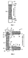
- FIG. 1 A schematic view of an exemplary prior art housing structure is shown in figure 1 .
- the structure has a metallic frame fabricated from box section frames or posts 101 to which are welded L shaped brackets 102 having flanges 102a 102b.
- a double skin panel 103 is mounted to the frame as shown in figure 1 resting against the surface of the corner posts 101 and the flanges 102b.
- the other sides of the housing can be built up in the same way.
- the panels 103 can be secured to the box section frames or posts by means of rivets or screws, for example where a panel is required to be removable or demountable.
- the access space (Xmm in figure 1 ) is restricted to significantly less that the overall depth of the housing unit.
- the present invention provides a housing for HVAC apparatus, the housing comprising a frame to which panels are arranged to be fixed to define an enclosure, the frame comprising a panel receiving frame profile arranged to accommodate an edge of a first one of the panels, the panel receiving frame profile defining a seat for the panel edge, to locate against transverse surfaces of the panel, such that the panel is seated with its seated edge at a position outwardly of the inner skin of an adjacent transversely extending panel connected to the frame.
- the frame profile is typically an extruded profile of extruded material and it is therefore a unitary extruded profile which is formed to accommodate both the transversely extending panels.
- the seat is provided with a sealing formation enabling a seal to be formed against an internal facing skin of the panel.
- the sealing formation may comprise a rib upon which an elastomeric sealing strip can be mounted.
- the panel receiving frame profile defining the seat includes a securing formation arranged to interact with a securing formation on the panel to secure the panel in position.
- the securing formation on the frame profile is provided to connect with the panel at a position intermediate the position of the inner and outer skin of the panel, preferably adjacent a bridge portion of the panel which connects the inner and outer skins of the panel.
- the securing formation comprises a securing recess which is obscured by the panel when in position.
- the securing formation comprises an elongate longitudinally running slot formed integrally with the frame profile on an internal surface of the frame profile.
- the frame profile may be of extruded metallic construction in which case the securing formation is beneficially extruded integrally with the frame profile.
- the frame profile has a further seat for the adjacent transversely extending panel. It is preferred that the further seat supports the lower skin of the adjacent transversely extending panel at a level spaced inwardly of the said edge of the first one of the panels.
- the seats for the adjacent transversely extending panels are preferably provided on the same frame member.
- the seats are separated by a structural spacer section of the profile frame member. This may be a closed frame cell portion to increase the structural strength of the frame.
- the present invention provides a panel comprising an outer skin and an inner skin and a bridge connecting the outer and inner skins; the panel further comprising a securing arrangement mounted to the panel for securing the panel to a frame, the securing arrangement comprising a securing element movable from a stowed position to a deployed position projecting outwardly of the bridge.
- the securing element is preferably stowed in the interior of the panel in the stowed position and extends to project through the bridge when in the deployed position.
- the securing member is actuatable to move pivotally or rotatably. This may be achieved by means of the securing element being mounted on a rotatable spindle in the interior of the panel.
- the invention provides a housing for HVAC apparatus, the housing comprising:
- the invention provides a connection system for HVAC housing components, the system comprising housing components having angled corner surfaces to together define an angled recess when the components are presented for connection, and a connection element to be positioned in the angled recess and comprising first and second limbs extending in opposed directions from an apex portion of the connection element, the first and second limbs being configured to each lie adjacent with a respective one of the angled corner surfaces of the housing components and being provided with a securing formation enabling securing to the respective housing component.
- connection using the connection element positioned in the angled recess provides that the connection does not result in connection components standing proud of the housing profile, but rather the fixings are tucked away in a recess. This makes the connection bracket less obtrusive and cumbersome.
- connection element is provided with a fixing, such as a through bore or slot for receiving a suspension rod or other suspension means such a suspension cable.
- a through bore is provided at the apex portion of the connection element for receiving the suspension rod or other suspension means.
- connection element includes a spacer projection extending into a gap between the connected components.
- the spacer projection may extend from the apex portion.
- the spacer portion can be dimensioned accurately to maintain a required spacing distance between the connected components. For example, the spacer may maintain the distance for correct compression of a seal between the components.
- the securing formations on the limbs comprise means for accommodating mechanical fixings.
- bolt holes may be provided on the limbs for accommodating connection bolts.
- the mechanical fixings (such as bolts) are accommodated so as not to project outwardly out of the recess.
- the invention provides a housing for HVAC apparatus, the housing comprising a frame and panel arrangement to define an enclosure, the frame arrangement of the housing comprising first and second longitudinally running frame members, spaced from one another at opposed sides at the top of the housing, the respective frame members including a respective longitudinally running slot communicating with a respective recess spaced outwardly of the slot, the slot and recess together receiving a respective edge of a sheet as a top cover for the housing.
- the top cover sheet is retained in a bowed configuration.
- the top cover sheet is retained in the slot and recess in a resiliently deformed condition such that the top cover sheet springs outwardly to be held in engagement within the slots and recesses in the frame members.
- a housing 1 constructed to enclose HVAC apparatus.
- the apparatus contained within the housing 1 may, for example, include multiple devices including fans, heat exchangers (for example for heat recovery), controllable baffles and the like.
- the housing may be roof mounted or suspended in the space above a suspended ceiling in a building.
- the housing 1 is shown in schematic side view in figure 2 , the view is of part of a top panel 3, part of a bottom panel 4 and a side panel 2 mounted to a respective upper or lower support frame member 5, 6 which is of extruded aluminium zinc alloy.
- the upper support frame member 5 comprises three sections, a side panel seat portion 5a, a top panel seat portion 5b and an interconnecting closed cell section 5c between the sections 5a and 5b.
- the lower support frame member 6 comprises three sections, a side panel seat portion 6a, a bottom panel seat portion 6b and an interconnecting closed cell section 6c between the sections 6a and 6b.
- the sections 5b, 5c and 6b 6c are generally similar.
- the top panel seat portion 5b comprises a flange upon which the top panel rests and may be secured y means of mechanical fixings or adhesives.
- the lower panel seat portion 6b comprises a flange to which the lower panel is secured by means of a bolt 7 and L shaped bracket 8, which has a transverse limb received in a slot 6d of the lower frame member.
- the side panel seat portion 6a for seating the lower edge of the side panel 2 comprises a channel section having an outer lip 6e extending upwardly which retains the lower edge of the side panel 2.
- the frame member 6 includes a projecting rib 6f which retains a compressible elastomeric seal 10 for sealing against the inner skin of the side panel 2.
- the closed cell section 6c acts as a spacer and provides rigidity to the frame structure. It is important to note that, when received in the lower frame member 6, the lower edge of the side panel 2 is positioned below the level of the inner skin of the adjacent bottom panel 4. Also, the lower frame member 6 does not have any part that projects significantly above the level of the inner skin 4a of the adjacent bottom panel 4. This means that when the side panel 2 is removed from the frame, maximum access clearance is available through the space between the upper and lower frame members 5, 6.
- the side panel seat portion 5a for seating the upper edge of the side panel 2 comprises an outer in-turned lip 5e extending inwardly from an outer marginal web 5h.
- the upper edge of the panel 2 abuts against the lip 5e.
- the receiving slot 5a runs along the length of the frame member 5 and is formed integrally during the extrusion procedure.
- the slot is positioned at a position intermediately between 9and above) the inner and outer skin of the side panel.
- the locking element is retained in a stowed position substantially entirely within the interior of the panel 2 and, when the panel is correctly positioned with respect to the frame member 5, can be deployed to project upwardly through an aperture in the upper bridge surface 2c of the panel connecting the inner and outer skins 2a 2b, in order to engage within the longitudinally running retaining slot 5j.
- the retaining element is rotatably mounted on a mounting spindle 13.
- a rotatable drive shaft 14 connects with the securing element 12.
- a drive head 15 connects with the drive shaft 14 and is mounted to the outer skin 2b of the side panel. Using a screwdriver or other tool to rotate the head 15 causes the drive shaft 14 and hence the securing element to be rotatably moved between the stowed and deployed positions.
- a number of actuatable securing elements may be provided at different points along the length of the side panel 2 (i.e. into the plane of the paper in the figure). Also the retaining slot can be incorporated to accommodate foxing of top and bottom panels if required, as can be seen at 5k 6k.
- the frame member 5 includes a projecting rib 5f which retains a compressible elastomeric seal 10 for sealing against the inner skin of the side panel 2.
- the closed cell section 5c acts as a spacer and provides rigidity to the frame structure. It is important to note that, when received in the upper frame member 5, the upper edge 2c of the side panel 2 is positioned above the level of the inner skin 3a of the adjacent, transversely extending, top panel 3. Also, the upper frame member 5 does not have any part that projects significantly below the level of the inner skin 3a of the adjacent top panel 3. This means that when the side panel 2 is removed from the frame, maximum access clearance is available through the space between the upper and lower frame members 5, 6. This enables relatively larger components to be accommodated and serviced in the interior housing than is possible with comparable prior art constructions such as that shown in figure 1 .
- the design is particularly versatile, enabling additional panels 502, 503, 505 to be accommodated to provide enhanced acoustic and/or thermal insulation.
- housing units can be connected using a novel connection system.
- Figure 6 shows a first housing 601 to be connected to a second housing 701.
- the first housing includes a panel 602 mounted between extruded frame members 620, 621.
- the second housing 701 has a panel 702 mounted between frame members (only frame member 721 is shown).
- the connection system of the invention provides for improved connection between housing components, particularly frame members such as adjacent or abutting frame members 620, 721.
- the adjacent or abutting frame members 620, 721 are provided with angled edge surfaces 620a 721 a, that together defme an angled recess 725 when the components are set up for connection.
- connection system further includes a connection bracket 750 which has limbs 750a 750b extending in V shaped configuration in opposed directions from an apex portion 750c of the connection bracket.
- the angle between the limbs750a 750b is matched to the angle at which the angled edge surfaces 620a 721 a of the frame members are set.
- the bracket 750 is provided with a spacer rib 750d which extends from the apex of the bracket 750 between the frame members 620 721.
- the spacer rib 750d can be dimensioned accurately to maintain a required spacing distance between the connected components. For example, the spacer may maintain the distance for correct compression of a seal that may be provided between the components.
- the limbs 750a, 750b are arranged to be secured to the respective angled edge surfaces 620a 721 a, that together define an angled recess 725 when the components are set up for connection.
- the limbs and the angled edge surfaces 620a 721a are provided with holes for accommodating mechanical fixings such as the bolts 761.
- the connection system of the invention provides that the mechanical fixings (such as bolts) can be conveniently accommodated so as not to project outwardly out of the angled recess 725 defined by the angled edge surfaces 620a 721a.
- Connection using the connection bracket positioned in the angled recess provides that the connection does not result in connection components standing proud of the housing profile, but rather the fixings are tucked away in a recess. This makes the connection bracket less obtrusive and cumbersome.
- the bracket is provided with a through bore 750e at the apex portion for receiving a suspension rod 771 or other suspension means such a suspension cable. This enables the assembly to be suspended from a supporting structure.
- the housing 801 is provided with a top cover or roof 855.
- the top cover 855 is formed from a sheet of aluminium zinc alloy.
- the frame of the housing 801 has at each longitudinally running upper edge, a frame member 860 shown in perspective section in figure 9 . Only a fragment of the frame member 860 is shown for ease of explanation.
- the frame members 860, running along both opposed longitudinal edges of the housing 801 are used to releasably retain the top sheet 855 in bowed flexed configuration without the necessity of other mechanical fixings.
- the frame members 860 have a respective longitudinally running slot 865 between a pair of guide tongues 866 867.
- the slot 865 communicates with a recess 868 positioned peripherally outwardly of the slot 865 and below the tongue 866.
- the longitudinally running edge of the top cover sheet 855 is inserted into the slot 865 and anchors in the recess 868.
- the tongue 866 overlays the peripheral edge of the top cover sheet 855.
- the tongue 867 lies under the top cover sheet 855.
- the top cover sheet 855 is retained in a bowed configuration.
- the top cover sheet is retained in the slot and recess in a resiliently deformed condition such that the top cover sheet springs outwardly to be held in engagement within the slots and recesses in the frame members 860.
- the bowed configuration provides that that rainwater and condensation will run off the top cover sheet 855. Water leaking into the frame member can be channelled away along channels or grooves 870 provided in the extruded profile of the frame member 860.
Landscapes
- Engineering & Computer Science (AREA)
- Chemical & Material Sciences (AREA)
- Combustion & Propulsion (AREA)
- Mechanical Engineering (AREA)
- General Engineering & Computer Science (AREA)
- Body Structure For Vehicles (AREA)
- Air-Conditioning For Vehicles (AREA)
Applications Claiming Priority (1)
| Application Number | Priority Date | Filing Date | Title |
|---|---|---|---|
| GB0919761A GB2475270A (en) | 2009-11-12 | 2009-11-12 | Housing for HVAC apparatus |
Publications (2)
| Publication Number | Publication Date |
|---|---|
| EP2322868A2 true EP2322868A2 (de) | 2011-05-18 |
| EP2322868A3 EP2322868A3 (de) | 2015-04-15 |
Family
ID=41509216
Family Applications (1)
| Application Number | Title | Priority Date | Filing Date |
|---|---|---|---|
| EP10190727.7A Withdrawn EP2322868A3 (de) | 2009-11-12 | 2010-11-10 | Gehäuse für Klimaanlage |
Country Status (2)
| Country | Link |
|---|---|
| EP (1) | EP2322868A3 (de) |
| GB (1) | GB2475270A (de) |
Cited By (2)
| Publication number | Priority date | Publication date | Assignee | Title |
|---|---|---|---|---|
| CN107367042A (zh) * | 2017-08-29 | 2017-11-21 | 博纳环境设备(太仓)有限公司 | 一种高强度断冷桥空调箱箱板结构及其组装工艺 |
| US11635214B2 (en) | 2019-12-20 | 2023-04-25 | Johnson Controls Tyco IP Holdings LLP | Base pan for HVAC system |
Citations (1)
| Publication number | Priority date | Publication date | Assignee | Title |
|---|---|---|---|---|
| CN200989652Y (zh) * | 2006-10-10 | 2007-12-12 | 徐怀平 | 单元板组合式空调风柜壳体 |
Family Cites Families (17)
| Publication number | Priority date | Publication date | Assignee | Title |
|---|---|---|---|---|
| US2156347A (en) * | 1935-06-08 | 1939-05-02 | American Houses Inc | Stud and like element |
| US3261493A (en) * | 1963-04-18 | 1966-07-19 | Lockheed Aircraft Corp | Structural joint for a cargo container |
| DE1579568C3 (de) * | 1965-07-10 | 1975-02-06 | Stif Societa Tecnico Industriale Frigorifera S.P.A., Vicenza (Italien) | Vorgefertigte, wärmeisolierende Platten, die unter Verwendung von Spannelementen zusammenfügbar sind |
| SE370746C (sv) * | 1971-06-24 | 1978-02-27 | Gullfiber Ab | Hornprofil for hopmontering av vegg-, tak- resp golvpaneler |
| CA967324A (en) * | 1973-01-09 | 1975-05-13 | Reinhold E. Eder (Jr.) | Enclosure structure |
| CH564458A5 (de) * | 1974-04-10 | 1975-07-31 | Orion Werke Ag | |
| FR2500113A1 (fr) * | 1981-02-13 | 1982-08-20 | Bouton Michel | Enceinte thermiquement isolante constituee de panneaux modulaires |
| EP0072382B1 (de) * | 1981-08-07 | 1985-12-27 | SITRAPLAST Société anonyme dite: | Abdeckungskonstruktion zur Bildung eines Gewölbes |
| DE3533144A1 (de) * | 1985-09-17 | 1987-04-02 | Eternit Ag | Auf einem aufsetzkranz oder dergleichen angeordnetes, gewoelbtes dachoberlicht |
| GB2215004B (en) * | 1988-01-28 | 1991-07-17 | Thermac Spa | Elongate section member for supporting and connecting panels |
| BE1010205A3 (nl) * | 1996-05-02 | 1998-03-03 | Spapen Eric | Prefabconstructie en samenstellende elementen hierbij aangewend. |
| FR2761388B1 (fr) * | 1997-03-25 | 1999-06-11 | Dagard | Poteau d'angle destine au raccordement de deux panneaux de cloisons |
| FR2810352B1 (fr) * | 2000-06-15 | 2002-12-27 | Plasteurop Metecno Frigo Syste | Poteau d'angle pour l'assemblage de deux panneaux |
| AUPR831901A0 (en) * | 2001-10-17 | 2001-11-08 | Aaron Smith Pty Ltd | Demountable building |
| FR2884535B1 (fr) * | 2005-04-18 | 2011-01-21 | Ecodis Etude Coordination Distrib | Abri telescopique |
| DE502006005868D1 (de) * | 2005-08-19 | 2010-02-25 | Freudenberg Carl Kg | Befeuchter |
| KR100700612B1 (ko) * | 2006-01-03 | 2007-03-28 | 엘지전자 주식회사 | 조립식 냉장고의 단열 판넬의 결합 구조 및 이를 구비한조립식 냉장고 |
-
2009
- 2009-11-12 GB GB0919761A patent/GB2475270A/en not_active Withdrawn
-
2010
- 2010-11-10 EP EP10190727.7A patent/EP2322868A3/de not_active Withdrawn
Patent Citations (1)
| Publication number | Priority date | Publication date | Assignee | Title |
|---|---|---|---|---|
| CN200989652Y (zh) * | 2006-10-10 | 2007-12-12 | 徐怀平 | 单元板组合式空调风柜壳体 |
Cited By (3)
| Publication number | Priority date | Publication date | Assignee | Title |
|---|---|---|---|---|
| CN107367042A (zh) * | 2017-08-29 | 2017-11-21 | 博纳环境设备(太仓)有限公司 | 一种高强度断冷桥空调箱箱板结构及其组装工艺 |
| CN107367042B (zh) * | 2017-08-29 | 2023-02-28 | 博纳环境设备(太仓)有限公司 | 一种高强度断冷桥空调箱箱板结构及其组装工艺 |
| US11635214B2 (en) | 2019-12-20 | 2023-04-25 | Johnson Controls Tyco IP Holdings LLP | Base pan for HVAC system |
Also Published As
| Publication number | Publication date |
|---|---|
| GB0919761D0 (en) | 2009-12-30 |
| GB2475270A (en) | 2011-05-18 |
| EP2322868A3 (de) | 2015-04-15 |
Similar Documents
| Publication | Publication Date | Title |
|---|---|---|
| JP5130800B2 (ja) | エレベータのカゴ室 | |
| JP4896113B2 (ja) | リフォーム用窓枠取付構造 | |
| EP3334262B1 (de) | Universal-gang-einhausungssäulenadapter | |
| KR101592152B1 (ko) | 구조보강과 간편하게 시공할 수 있는 발코니 개보수 창호와 그 시공 방법 | |
| US12345039B2 (en) | Modular building system | |
| EP2045436B1 (de) | Multifunktionelles Führungsprofil für Mobilbildschirme und Befestigungssystem mit einem derartigen Profil | |
| EP2322868A2 (de) | Gehäuse für Klimaanlage | |
| JP5433544B2 (ja) | 改装サッシユニット及び改装サッシユニットの取付方法 | |
| US20060223434A1 (en) | System and method for mounting a fresh air exchanger to a window frame assembly | |
| CN107449060B (zh) | 窗式空调器 | |
| KR102015433B1 (ko) | 커튼월 | |
| JP2010126910A (ja) | サッシ | |
| JP2009108485A (ja) | シャッターボックスの取付構造 | |
| JP2006342542A (ja) | 引違いサッシの下枠改装構造 | |
| JP6202881B2 (ja) | 開口部の防水装置 | |
| JP5271324B2 (ja) | たてすべり出し窓 | |
| US11352807B2 (en) | Urban hide screen for surveillance operations in urban environments | |
| CN218264514U (zh) | 一种装饰板与吊顶的收口结构 | |
| JP7358578B2 (ja) | カーテンウォールユニット | |
| JP5345088B2 (ja) | 換気扇 | |
| KR102931347B1 (ko) | 창문형 에어컨 | |
| JP5064185B2 (ja) | 胴縁、胴縁受け部材、下地部材、下地部材の取付方法及び建築物 | |
| CN110546336A (zh) | 用于安装百叶窗板片的结构 | |
| JP4039568B2 (ja) | カーテンウオール | |
| AU2006202625B2 (en) | A framing member |
Legal Events
| Date | Code | Title | Description |
|---|---|---|---|
| PUAI | Public reference made under article 153(3) epc to a published international application that has entered the european phase |
Free format text: ORIGINAL CODE: 0009012 |
|
| AK | Designated contracting states |
Kind code of ref document: A2 Designated state(s): AL AT BE BG CH CY CZ DE DK EE ES FI FR GB GR HR HU IE IS IT LI LT LU LV MC MK MT NL NO PL PT RO RS SE SI SK SM TR |
|
| AX | Request for extension of the european patent |
Extension state: BA ME |
|
| PUAL | Search report despatched |
Free format text: ORIGINAL CODE: 0009013 |
|
| AK | Designated contracting states |
Kind code of ref document: A3 Designated state(s): AL AT BE BG CH CY CZ DE DK EE ES FI FR GB GR HR HU IE IS IT LI LT LU LV MC MK MT NL NO PL PT RO RS SE SI SK SM TR |
|
| AX | Request for extension of the european patent |
Extension state: BA ME |
|
| RIC1 | Information provided on ipc code assigned before grant |
Ipc: F24F 13/20 20060101AFI20150311BHEP |
|
| 17P | Request for examination filed |
Effective date: 20151015 |
|
| RBV | Designated contracting states (corrected) |
Designated state(s): AL AT BE BG CH CY CZ DE DK EE ES FI FR GB GR HR HU IE IS IT LI LT LU LV MC MK MT NL NO PL PT RO RS SE SI SK SM TR |
|
| 17Q | First examination report despatched |
Effective date: 20200320 |
|
| STAA | Information on the status of an ep patent application or granted ep patent |
Free format text: STATUS: THE APPLICATION IS DEEMED TO BE WITHDRAWN |
|
| 18D | Application deemed to be withdrawn |
Effective date: 20201001 |