EP2322902A2 - System and method for determining heading - Google Patents
System and method for determining heading Download PDFInfo
- Publication number
- EP2322902A2 EP2322902A2 EP10014496A EP10014496A EP2322902A2 EP 2322902 A2 EP2322902 A2 EP 2322902A2 EP 10014496 A EP10014496 A EP 10014496A EP 10014496 A EP10014496 A EP 10014496A EP 2322902 A2 EP2322902 A2 EP 2322902A2
- Authority
- EP
- European Patent Office
- Prior art keywords
- point
- time
- vector
- unit
- heading
- Prior art date
- Legal status (The legal status is an assumption and is not a legal conclusion. Google has not performed a legal analysis and makes no representation as to the accuracy of the status listed.)
- Granted
Links
Images


Classifications
-
- G—PHYSICS
- G01—MEASURING; TESTING
- G01C—MEASURING DISTANCES, LEVELS OR BEARINGS; SURVEYING; NAVIGATION; GYROSCOPIC INSTRUMENTS; PHOTOGRAMMETRY OR VIDEOGRAMMETRY
- G01C21/00—Navigation; Navigational instruments not provided for in groups G01C1/00 - G01C19/00
- G01C21/10—Navigation; Navigational instruments not provided for in groups G01C1/00 - G01C19/00 by using measurements of speed or acceleration
- G01C21/12—Navigation; Navigational instruments not provided for in groups G01C1/00 - G01C19/00 by using measurements of speed or acceleration executed aboard the object being navigated; Dead reckoning
-
- G—PHYSICS
- G01—MEASURING; TESTING
- G01C—MEASURING DISTANCES, LEVELS OR BEARINGS; SURVEYING; NAVIGATION; GYROSCOPIC INSTRUMENTS; PHOTOGRAMMETRY OR VIDEOGRAMMETRY
- G01C21/00—Navigation; Navigational instruments not provided for in groups G01C1/00 - G01C19/00
- G01C21/005—Navigation; Navigational instruments not provided for in groups G01C1/00 - G01C19/00 with correlation of navigation data from several sources, e.g. map or contour matching
-
- G—PHYSICS
- G01—MEASURING; TESTING
- G01C—MEASURING DISTANCES, LEVELS OR BEARINGS; SURVEYING; NAVIGATION; GYROSCOPIC INSTRUMENTS; PHOTOGRAMMETRY OR VIDEOGRAMMETRY
- G01C21/00—Navigation; Navigational instruments not provided for in groups G01C1/00 - G01C19/00
- G01C21/10—Navigation; Navigational instruments not provided for in groups G01C1/00 - G01C19/00 by using measurements of speed or acceleration
- G01C21/12—Navigation; Navigational instruments not provided for in groups G01C1/00 - G01C19/00 by using measurements of speed or acceleration executed aboard the object being navigated; Dead reckoning
- G01C21/16—Navigation; Navigational instruments not provided for in groups G01C1/00 - G01C19/00 by using measurements of speed or acceleration executed aboard the object being navigated; Dead reckoning by integrating acceleration or speed, i.e. inertial navigation
- G01C21/165—Navigation; Navigational instruments not provided for in groups G01C1/00 - G01C19/00 by using measurements of speed or acceleration executed aboard the object being navigated; Dead reckoning by integrating acceleration or speed, i.e. inertial navigation combined with non-inertial navigation instruments
- G01C21/1656—Navigation; Navigational instruments not provided for in groups G01C1/00 - G01C19/00 by using measurements of speed or acceleration executed aboard the object being navigated; Dead reckoning by integrating acceleration or speed, i.e. inertial navigation combined with non-inertial navigation instruments with passive imaging devices, e.g. cameras
-
- G—PHYSICS
- G06—COMPUTING OR CALCULATING; COUNTING
- G06T—IMAGE DATA PROCESSING OR GENERATION, IN GENERAL
- G06T7/00—Image analysis
- G06T7/70—Determining position or orientation of objects or cameras
- G06T7/73—Determining position or orientation of objects or cameras using feature-based methods
-
- G—PHYSICS
- G06—COMPUTING OR CALCULATING; COUNTING
- G06T—IMAGE DATA PROCESSING OR GENERATION, IN GENERAL
- G06T2207/00—Indexing scheme for image analysis or image enhancement
- G06T2207/10—Image acquisition modality
- G06T2207/10016—Video; Image sequence
-
- G—PHYSICS
- G06—COMPUTING OR CALCULATING; COUNTING
- G06T—IMAGE DATA PROCESSING OR GENERATION, IN GENERAL
- G06T2207/00—Indexing scheme for image analysis or image enhancement
- G06T2207/30—Subject of image; Context of image processing
- G06T2207/30244—Camera pose
-
- G—PHYSICS
- G06—COMPUTING OR CALCULATING; COUNTING
- G06T—IMAGE DATA PROCESSING OR GENERATION, IN GENERAL
- G06T2207/00—Indexing scheme for image analysis or image enhancement
- G06T2207/30—Subject of image; Context of image processing
- G06T2207/30248—Vehicle exterior or interior
Definitions
- the present invention relates generally to navigations systems, and more particularly to systems and methods for determining heading.
- a low grade inertial measurement unit cannot determine its heading angle accurately unless the vehicle experiences significant velocity changes from time to time. For example, without velocity change, the heading accuracy of an IMU equipped with 1 deg/hr gyros aided by GPS is about 0.1 radians.
- a traditional way to align low grade IMU equipment with GPS or some other external position/velocity reference is to employ S-turns during travel to provide observability of heading errors.
- Traditional in-flight alignment procedures require the vehicle to execute lengthy horizontal-plane S-turns maneuvers lasting several minutes. Although capable of attaining milliradian alignment accuracy, lengthy traditional alignment procedures generally distract from the goals of a given mission.
- a system for determining heading that is mountable on a traveling vehicle.
- the system comprises an image system that captures multiple distinctive features in an area of interest at a first point in time and at a second point of time during traveling of the traveling vehicle, matches the multiple distinctive features captured at the first point of time and the second point of time, and determines a first unit-vector associated with a given matched distinctive feature based on the first point in time and a second unit-vector associated with the given matched distinctive feature associated with the second point in time for each of the multiple matched distinctive features.
- the system further comprises a global positioning system (GPS) that determines a translation vector based on carrier phase information captured from the first point in time to the second point in time and a coupled processor that minimizes the error in an epipolar equation for each of the multiple matched distinctive features based on the respective first and second unit-vectors and the translation vector to determine a corrected heading.
- GPS global positioning system
- a system for determining heading that is mountable on a traveling vehicle.
- the system comprises an image system that captures multiple distinctive features in an area of interest at a first point in time and at a second point of time during traveling of the traveling vehicle, matches the multiple distinctive features captured at the first point of time and the second point of time, and determines a first unit-vector associated with a given matched distinctive feature based on the first point in time and a second unit-vector associated with the given matched distinctive feature associated with the second point in time for each of the multiple matched distinctive features.
- the system further comprises a global positioning system (GPS) that determines a translation vector based on carrier phase information captured from the first point in time to the second point In time and a coupled processor that minimizes the error in an epipolar equation for each of the multiple matched distinctive features based on the first and second unit-vectors and the translation vector to determine a corrected heading.
- GPS global positioning system
- the system also comprises an inertial measurement system that provides an initial heading to the coupled processor, such that the coupled processor employs the initial heading at a starting point for minimizing the epipolar equation,
- a method for determining heading of a traveling vehicle employing an image system, an inertial system and a global positioning system (GPS).
- the method comprises capturing imagery in an area of interest and extracting multiple distinctive feature coordinates at a first point in time, capturing imagery in the area of interest and extracting multiple distinctive feature coordinates at a second point in time and matching the multiple distinctive feature coordinates captured at the first point of time and the second point of time to determine multiple matched distinctive features.
- the method further comprises providing a first unit-vector associated with a given matched distinctive feature based on the first point in time and a second unit-vector associated with the given matched distinctive feature associated with the second point in time for each of the multiple matched distinctive features, computing a translation vector based on carrier phase information captured from the first point in time to the second point in time and minimizing an epipolar equation for each of the multiple matched distinctive features based on the first and second unit-vectors and the translation vector to determine a corrected heading.
- FIG. 1 illustrates a block diagram of a system for determining heading in accordance with an aspect of the invention.
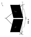
- FIG. 2 illustrates an epipolar geometry graph that facilitates the describing of the computations performed by the coupled processor in accordance with an aspect of the present invention.
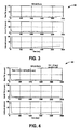
- FIG. 3 illustrates a graph of inertial orientation errors versus time on a first simulation performed with free inertial orientation errors of baro-aided navigation-grade Inertial Navigation System (INS) without GPS and with an S-turn alignment maneuver.
- INS Inertial Navigation System
- FIG. 4 illustrates a graph of inertial orientation errors versus time on a second simulation performed without S-turn alignment employing baro-aided navigation-grade INS with continuous alignment vision observations in accordance with an aspect of the present invention.
- FIG. 5 illustrates a methodology for determining heading in accordance with an aspect of the invention.
- a system for determining heading that is mountable on a traveling vehicle.
- the system comprises an image system that identifies and tracks multiple distinctive features in an area of interest at successive points in time during motion of the traveling vehicle.
- the vision processing procedure involves matching multiple features and then determining a unit-vector associated with each of these matched distinctive features.
- the system further comprises a global positioning system (GPS) that determines a translation vector based on carrier phase information captured from the first point in time to the second point in time and a coupled processor that minimizes the error in an epipolar equation (EQ. 1) for each of the multiple matched distinctive features based on the respective first and second unit-vectors and the translation vector.
- GPS global positioning system
- EQ. 1 an epipolar equation
- platform alignment requires two steps: the determination of the relationship between an arbitrary earth-fixed frame and the body frame and then the determination of this earth-fixed frame with respect to known earth-fixed frame (e.g., North, East, Down). With enough matched features, the vision observations can be combined into platform pose referenced in an earth-fixed coordinate frame (relation to North, East, and Down is not yet known). Then a coupled processor can combine the vision observation with the GPS measurement to determine the final alignment between the body frame and the known earth-fixed frame.
- known earth-fixed frame e.g., North, East, Down
- the coupled processor employs the GPS translation and the vision observation with the epipolar equation (EQ. 3) to directly solve for the initial heading at the starting point.
- an inertial measurement system can provide an initial heading at the starting point to the coupled processor.
- FIG. 1 illustrates a system 10 for determining heading in accordance with an aspect of the present invention.
- the system 10 includes an inertial measurement system 12, an image system 18 and a global position system (GPS) 24 mounted on a traveling vehicle (not shown).
- the inertial measurement system 12 includes a relatively inexpensive inertial measurement unit (IMU) 14 and an inertial processor 16.
- the image system 18 includes an image sensor 20 (e.g., a camera) and an image processor 22.
- the GPS 24 includes a GPS receiver 26 and a GPS processor 28. Multiple distinctive features of an image area are captured by the image sensor 20 at a first point in time (t 1 ) and a second point in time (t 2 ) during motion of the traveling vehicle.
- a first unit-vector (x 1 ) can be determined at the first point time (t 1 ) and a second unit-vector (x 2 ) can be determined at the second point in time (t 2 ) for each of the multiple matched features by the image processor 22.
- the image processor 22 provides the first unit-vector (x 1 ) and the second unit-vector (x 2 ) for each of the multiple features to a coupled processor 30.
- a translation vector T GPS can be determined by the GPS processor 28 based on carrier phase information captured by the GPS receiver 26 from the first point in time (t 1 ) to the second point in time (t 2 ).
- the GPS processor 28 provides the translation vector T GPS to the coupled processor 30.
- changes in velocity ( ⁇ V) and attitude ( ⁇ ) are provided from the IMU 14 to the inertial processor 16 along with translation information from the GPS processor 28, such that the coupled processor 30 can determine initial position, attitude and heading.
- the IMU 14 continues providing changes in velocity and attitude and the inertial processor 16 propagates the position, attitude and heading between the first point in time (t 1 ) and the second point in time (t 2 ). These values are provided to the coupled processor 30, which also feeds back correction information to the inertial processor 16.
- the translation vector T GPS is determined by the GPS processor 28 in the navigation frame N (north-east-down) and the first unit-vector x 1 and the second unit-vector x 2 are determined by the image processor 22 that is rigidly related to the body frame B of the IMU 14.
- the coupled processor 30 averages the heading angles derived from the multiple distinctive features and outputs an initial heading alignment for the system 10.
- the system 10 for determining heading has many useful applications. Primarily, this technique allows the use of a low cost stand-alone GPS-IMU-Camera package in an aircraft, a land vehicle, or a helicopter to determine Its heading without the need for custom trajectories or maneuvers such as S-turns. It can also be applied to the situation where some kind of vision sensor is already available, for example Electro/Optical sensors or a SAR (Synthetic Aperture Radar).
- FIG. 2 illustrates an epipolar geometry graph 40 that facilitates the describing of the computations performed by the coupled processor in accordance with an aspect of the present invention.
- a feature at location p in 3D space is observed by an image sensor at two times ( t 1 , and t 2 ) located at points O 1 and O 2 , respectively.
- Let X 1 and X 2 be the vectors from o 1 and o 2 to p , respectively in the north-east-down navigation coordinate frame ( N ).
- T be the translation vector from o 1 to o 2 .
- the image sensor provides the direction (unit-vector) to the feature. It is measured in the image sensor frame, which is rigidly related to the body frame ( B ) of the IMU, and then transformed to the navigation frame.
- the coupled processor 30 is a Kalman filter.
- the solution above can be refined by using a Kalman filter as described below. Since the image sensor frame is related to the IMU frame, the image measurements share the same attitude error as the IMU frame.
- FIG. 3 illustrates a graph 50 of inertial orientation errors versus time on a first simulation performed with free inertial orientation errors of baro-aided navigation-grade INS during GPS denial after S-turn alignment.
- FIG. 4 illustrates a graph 60 of inertial orientation errors versus time on a second simulation performed without S-turn alignment employing baro-aided INS with continuous alignment using an image sensor in accordance with an aspect of the present invention.
- the baro-aided free inertial orientation accuracy (1 ⁇ from 30 Monte Carlo runs) with S-turn alignment and without vision is illustrated in FIG. 3 .
- the heading accuracy is the primary beneficiary of alignment procedures since the S-turn maneuver can be removed when vision is included and the performance is nearly the same.
- vision aiding was provided by a downward looking EO vision sensor matching five features between sequential frames.
- the simulated vision accuracy consisted of a feature noise of 0.22 mrad and a feature range accuracy of 0.1% of the total range. These parameters would be representative of a high-performance camera.
- the corresponding orientation accuracy with vision alignment without S-turns is Illustrated in FIG. 4 . It should be noted that FIG. 4 illustrates similar heading alignment accuracy using vision as the S-turn case in FIG. 3 without the need to add special maneuvers (such as S-turns) to the mission profile.
- FIG. 5 a methodology in accordance with various aspects of the present invention will be better appreciated with reference to FIG. 5 . While, for purposes of simplicity of explanation, the methodology of FIG. 5 is shown and described as executing serially, it is to be understood and appreciated that the present invention is not limited by the illustrated order, as some aspects could, in accordance with the present invention, occur in different orders and/or concurrently with other aspects from that shown and described herein. Moreover, not all illustrated features may be required to implement a methodology in accordance with an aspect of the present invention.
- FIG. 5 illustrates an example of a methodology 70 for determining heading in accordance with an aspect of the invention.
- the methodology employs an image system, an inertial measurement system and a GPS mounted on a traveling vehicle.
- imagery of an image area is captured by the image sensor at a first point in time (t 1 ) during traveling of the traveling vehicle and multiple distinctive feature coordinates are extracted by image processing.
- imagery of the image area is captured by the image sensor at a second point in time (t 2 ) during traveling of the traveling vehicle and multiple distinctive feature coordinates are extracted by image processing.
- the distinctive feature coordinates are matched and a first unit-vector (x 1 ) is determined based on the first point time (t 1 ) and a second unit vector (x 2 ) is determined based on the second point in time (t 2 ) for each of the multiple matched distinctive features.
- the methodology 70 then proceeds to 78.
- a translation vector T GPS is computed based on carrier phase information provided by a GPS device from the first point in time (t 1 ) to the second point in time (t 2 ).
- an inertial measurement system that provides an initial leveling to the coupled processor.
- the coupled processor can employ the initial leveling to directly solve the epipolar equation for heading based on EQ. 3.
- the error in the epipolar equation is minimized for each matched distinctive feature based on the first unit-vector (x 1 ) and the second unit vector (x 2 ) for a given matched distinctive feature, the translation vector T GPS , and the initial leveling from 80 to determine a corrected heading associated with each of the matched distinctive features.
- the corrected headings can be averaged to provide a finely aligned corrected heading.
- the epipolar geometry equation can be based on EQ. 3 when directly computing the initial heading, or based on EQ. 8 if an IMU is available.
- the coupled processor can use a Kalman filter to continuously refine the heading.
Landscapes
- Engineering & Computer Science (AREA)
- Radar, Positioning & Navigation (AREA)
- Remote Sensing (AREA)
- Physics & Mathematics (AREA)
- General Physics & Mathematics (AREA)
- Automation & Control Theory (AREA)
- Computer Vision & Pattern Recognition (AREA)
- Theoretical Computer Science (AREA)
- Navigation (AREA)
- Position Fixing By Use Of Radio Waves (AREA)
- Length Measuring Devices By Optical Means (AREA)
Abstract
Description
- The present invention relates generally to navigations systems, and more particularly to systems and methods for determining heading.
- Even with the utilization of a global positioning system (GPS), a low grade inertial measurement unit (IMU) cannot determine its heading angle accurately unless the vehicle experiences significant velocity changes from time to time. For example, without velocity change, the heading accuracy of an IMU equipped with 1 deg/hr gyros aided by GPS is about 0.1 radians. A traditional way to align low grade IMU equipment with GPS or some other external position/velocity reference is to employ S-turns during travel to provide observability of heading errors. Traditional in-flight alignment procedures require the vehicle to execute lengthy horizontal-plane S-turns maneuvers lasting several minutes. Although capable of attaining milliradian alignment accuracy, lengthy traditional alignment procedures generally distract from the goals of a given mission.
- In one embodiment of the invention, a system is provided for determining heading that is mountable on a traveling vehicle. The system comprises an image system that captures multiple distinctive features in an area of interest at a first point in time and at a second point of time during traveling of the traveling vehicle, matches the multiple distinctive features captured at the first point of time and the second point of time, and determines a first unit-vector associated with a given matched distinctive feature based on the first point in time and a second unit-vector associated with the given matched distinctive feature associated with the second point in time for each of the multiple matched distinctive features. The system further comprises a global positioning system (GPS) that determines a translation vector based on carrier phase information captured from the first point in time to the second point in time and a coupled processor that minimizes the error in an epipolar equation for each of the multiple matched distinctive features based on the respective first and second unit-vectors and the translation vector to determine a corrected heading.
- In another embodiment of the invention, a system is provided for determining heading that is mountable on a traveling vehicle. The system comprises an image system that captures multiple distinctive features in an area of interest at a first point in time and at a second point of time during traveling of the traveling vehicle, matches the multiple distinctive features captured at the first point of time and the second point of time, and determines a first unit-vector associated with a given matched distinctive feature based on the first point in time and a second unit-vector associated with the given matched distinctive feature associated with the second point in time for each of the multiple matched distinctive features. The system further comprises a global positioning system (GPS) that determines a translation vector based on carrier phase information captured from the first point in time to the second point In time and a coupled processor that minimizes the error in an epipolar equation for each of the multiple matched distinctive features based on the first and second unit-vectors and the translation vector to determine a corrected heading. The system also comprises an inertial measurement system that provides an initial heading to the coupled processor, such that the coupled processor employs the initial heading at a starting point for minimizing the epipolar equation,
- In yet a further embodiment of the invention, a method is provided for determining heading of a traveling vehicle employing an image system, an inertial system and a global positioning system (GPS). The method comprises capturing imagery in an area of interest and extracting multiple distinctive feature coordinates at a first point in time, capturing imagery in the area of interest and extracting multiple distinctive feature coordinates at a second point in time and matching the multiple distinctive feature coordinates captured at the first point of time and the second point of time to determine multiple matched distinctive features. The method further comprises providing a first unit-vector associated with a given matched distinctive feature based on the first point in time and a second unit-vector associated with the given matched distinctive feature associated with the second point in time for each of the multiple matched distinctive features, computing a translation vector based on carrier phase information captured from the first point in time to the second point in time and minimizing an epipolar equation for each of the multiple matched distinctive features based on the first and second unit-vectors and the translation vector to determine a corrected heading.
-
FIG. 1 illustrates a block diagram of a system for determining heading in accordance with an aspect of the invention. -
FIG. 2 illustrates an epipolar geometry graph that facilitates the describing of the computations performed by the coupled processor in accordance with an aspect of the present invention. -
FIG. 3 illustrates a graph of inertial orientation errors versus time on a first simulation performed with free inertial orientation errors of baro-aided navigation-grade Inertial Navigation System (INS) without GPS and with an S-turn alignment maneuver. -
FIG. 4 illustrates a graph of inertial orientation errors versus time on a second simulation performed without S-turn alignment employing baro-aided navigation-grade INS with continuous alignment vision observations in accordance with an aspect of the present invention. -
FIG. 5 illustrates a methodology for determining heading in accordance with an aspect of the invention. - Systems and methods are provided for determining heading using visual cues. The use of visual cues eliminates the need for S-turn maneuvers while providing similar performance and offers the potential to improve the heading accuracy when high quality instrumentation is used. In one embodiment of the invention, a system is provided for determining heading that is mountable on a traveling vehicle. The system comprises an image system that identifies and tracks multiple distinctive features in an area of interest at successive points in time during motion of the traveling vehicle. The vision processing procedure involves matching multiple features and then determining a unit-vector associated with each of these matched distinctive features. The system further comprises a global positioning system (GPS) that determines a translation vector based on carrier phase information captured from the first point in time to the second point in time and a coupled processor that minimizes the error in an epipolar equation (EQ. 1) for each of the multiple matched distinctive features based on the respective first and second unit-vectors and the translation vector. A Kalman filter (or some other optimal estimator) can be employed to continuously combine the measurements for a refined heading solution.
- It is to be appreciated that platform alignment requires two steps: the determination of the relationship between an arbitrary earth-fixed frame and the body frame and then the determination of this earth-fixed frame with respect to known earth-fixed frame (e.g., North, East, Down). With enough matched features, the vision observations can be combined into platform pose referenced in an earth-fixed coordinate frame (relation to North, East, and Down is not yet known). Then a coupled processor can combine the vision observation with the GPS measurement to determine the final alignment between the body frame and the known earth-fixed frame.
- In another embodiment of the invention, the coupled processor employs the GPS translation and the vision observation with the epipolar equation (EQ. 3) to directly solve for the initial heading at the starting point. Alternatively, an inertial measurement system can provide an initial heading at the starting point to the coupled processor.
- Hereafter the description of feature matching will be described as a match between two sequential points in time for illustration simplicity, but this operation could involve more than two points in time.
-
FIG. 1 illustrates asystem 10 for determining heading in accordance with an aspect of the present invention. Thesystem 10 includes aninertial measurement system 12, animage system 18 and a global position system (GPS) 24 mounted on a traveling vehicle (not shown). Theinertial measurement system 12 includes a relatively inexpensive inertial measurement unit (IMU) 14 and aninertial processor 16. Theimage system 18 includes an image sensor 20 (e.g., a camera) and animage processor 22. The GPS 24 includes aGPS receiver 26 and aGPS processor 28. Multiple distinctive features of an image area are captured by theimage sensor 20 at a first point in time (t1) and a second point in time (t2) during motion of the traveling vehicle. After matching of the multiple distinctive features, a first unit-vector (x1) can be determined at the first point time (t1) and a second unit-vector (x2) can be determined at the second point in time (t2) for each of the multiple matched features by theimage processor 22. Theimage processor 22 provides the first unit-vector (x1) and the second unit-vector (x2) for each of the multiple features to a coupledprocessor 30. A translation vector TGPS can be determined by theGPS processor 28 based on carrier phase information captured by theGPS receiver 26 from the first point in time (t1) to the second point in time (t2). TheGPS processor 28 provides the translation vector TGPS to the coupledprocessor 30. - During an initial alignment, changes in velocity (ΔV) and attitude (Δθ) are provided from the
IMU 14 to theinertial processor 16 along with translation information from theGPS processor 28, such that the coupledprocessor 30 can determine initial position, attitude and heading. The IMU 14 continues providing changes in velocity and attitude and theinertial processor 16 propagates the position, attitude and heading between the first point in time (t1) and the second point in time (t2). These values are provided to the coupledprocessor 30, which also feeds back correction information to theinertial processor 16. - The translation vector TGPS is determined by the
GPS processor 28 in the navigation frame N (north-east-down) and the first unit-vector x1 and the second unit-vector x2 are determined by theimage processor 22 that is rigidly related to the body frame B of theIMU 14. The coupledprocessor 30 is configured to solve and minimize the errors in the epipolar equation:
where x1 and x2 are first and second unit-vectors pointing to the same feature from points O1 and O2 ,respectively. For convenience (and ignoring the boresight error), it is assumed that the image frame and system body frame are the same. Also assuming that the roll and pitch angles of theIMU 14 are known (they are readily determined by measuring the gravity vector), It means the transformation matrix C from a navigation (N) frame to a local (L) frame.
- Based on ignoring the above known errors and based on the above known assumptions, the coupled
processor 30 determines the heading angle by solving the transformation matrix Cfrom a navigation (N) frame to a local (L) frame, such that

where c = cos(a) and s =sin(a); and a is the heading angle to be solved. - The initial heading angle a can be provided from the
inertial processor 16 and substituted into the following epipolar equation:
processor 30 until a heading angle is provided that provides results of the epipolar equation that are minimized (e.g., approximately 0). This is repeated for each of the multiple distinctive features. The coupledprocessor 30 averages the heading angles derived from the multiple distinctive features and outputs an initial heading alignment for thesystem 10. - The
system 10 for determining heading has many useful applications. Primarily, this technique allows the use of a low cost stand-alone GPS-IMU-Camera package in an aircraft, a land vehicle, or a helicopter to determine Its heading without the need for custom trajectories or maneuvers such as S-turns. It can also be applied to the situation where some kind of vision sensor is already available, for example Electro/Optical sensors or a SAR (Synthetic Aperture Radar). -
FIG. 2 illustrates anepipolar geometry graph 40 that facilitates the describing of the computations performed by the coupled processor in accordance with an aspect of the present invention. A feature at location p in 3D space is observed by an image sensor at two times (t1 , and t2 ) located at points O1 and O2 , respectively. Let X1 and X2 be the vectors from o1 and o2 to p, respectively in the north-east-down navigation coordinate frame (N). Let T be the translation vector from o1 to o2 . The image sensor provides the direction (unit-vector) to the feature. It is measured in the image sensor frame, which is rigidly related to the body frame (B) of the IMU, and then transformed to the navigation frame. For convenience (assuming unity focal length and ignoring the boresight error), it is assumed that the image sensor frame and IMU body frame are the same. For example,
The epipolar equation states that:
where "." is dot product and "x" is cross product.
The above equation simply states that the three vectors x1 , x2 , and Tare on the same plane. EQ. 5 can be rewritten as:
- In one aspect of the invention, the coupled
processor 30 is a Kalman filter. The solution above can be refined by using a Kalman filter as described below. Since the image sensor frame is related to the IMU frame, the image measurements share the same attitude error as the IMU frame. The error of EQ. 6 can be expressed as follows:

where φ= attitude error (tilt and heading error); δT translation error.
Since δT can be measured accurately by GPS, EQ. 8 provides enough information for the Kalman filter to resolve the attitude error φ (tilts and heading error). -
FIG. 3 illustrates agraph 50 of inertial orientation errors versus time on a first simulation performed with free inertial orientation errors of baro-aided navigation-grade INS during GPS denial after S-turn alignment.FIG. 4 illustrates agraph 60 of inertial orientation errors versus time on a second simulation performed without S-turn alignment employing baro-aided INS with continuous alignment using an image sensor in accordance with an aspect of the present invention. To illustrate the results, the baro-aided free inertial orientation accuracy (1σ from 30 Monte Carlo runs) with S-turn alignment and without vision is illustrated inFIG. 3 . The heading accuracy is the primary beneficiary of alignment procedures since the S-turn maneuver can be removed when vision is included and the performance is nearly the same. For this example, vision aiding was provided by a downward looking EO vision sensor matching five features between sequential frames. The simulated vision accuracy consisted of a feature noise of 0.22 mrad and a feature range accuracy of 0.1% of the total range. These parameters would be representative of a high-performance camera. The corresponding orientation accuracy with vision alignment without S-turns is Illustrated inFIG. 4 . It should be noted thatFIG. 4 illustrates similar heading alignment accuracy using vision as the S-turn case inFIG. 3 without the need to add special maneuvers (such as S-turns) to the mission profile. - In view of the foregoing structural and functional features described above, a methodology in accordance with various aspects of the present invention will be better appreciated with reference to
FIG. 5 . While, for purposes of simplicity of explanation, the methodology ofFIG. 5 is shown and described as executing serially, it is to be understood and appreciated that the present invention is not limited by the illustrated order, as some aspects could, in accordance with the present invention, occur in different orders and/or concurrently with other aspects from that shown and described herein. Moreover, not all illustrated features may be required to implement a methodology in accordance with an aspect of the present invention. -
FIG. 5 illustrates an example of amethodology 70 for determining heading in accordance with an aspect of the invention. The methodology employs an image system, an inertial measurement system and a GPS mounted on a traveling vehicle. At 72, imagery of an image area is captured by the image sensor at a first point in time (t1) during traveling of the traveling vehicle and multiple distinctive feature coordinates are extracted by image processing. At 74, imagery of the image area is captured by the image sensor at a second point in time (t2) during traveling of the traveling vehicle and multiple distinctive feature coordinates are extracted by image processing. At 76, the distinctive feature coordinates are matched and a first unit-vector (x1) is determined based on the first point time (t1) and a second unit vector (x2) is determined based on the second point in time (t2) for each of the multiple matched distinctive features. Themethodology 70 then proceeds to 78. - At 78, a translation vector TGPS is computed based on carrier phase information provided by a GPS device from the first point in time (t1) to the second point in time (t2). At 80, an inertial measurement system that provides an initial leveling to the coupled processor. The coupled processor can employ the initial leveling to directly solve the epipolar equation for heading based on EQ. 3. At 82, the error in the epipolar equation is minimized for each matched distinctive feature based on the first unit-vector (x1) and the second unit vector (x2) for a given matched distinctive feature, the translation vector TGPS, and the initial leveling from 80 to determine a corrected heading associated with each of the matched distinctive features. The corrected headings can be averaged to provide a finely aligned corrected heading. The epipolar geometry equation can be based on EQ. 3 when directly computing the initial heading, or based on EQ. 8 if an IMU is available. The coupled processor can use a Kalman filter to continuously refine the heading.
- What have been described above are examples of the present invention. It is, of course, not possible to describe every conceivable combination of components or methodologies for purposes of describing the present invention, but one of ordinary skill in the art will recognize that many further combinations and permutations of the present invention are possible. Accordingly, the present invention is intended to embrace all such alterations, modifications and variations that fall within the spirit and scope of the appended claims.
Claims (15)
- A system for determining heading that is mountable on a traveling vehicle, the system comprising:an image system that captures multiple distinctive features in an area of interest at a first point in time and at a second point of time during traveling of the traveling vehicle, matches the multiple distinctive features captured at the first point of time and the second point of time, and determines a first unit-vector associated with a given matched distinctive feature based on the first point in time and a second unit-vector associated with the given matched distinctive feature associated with the second point in time for each of the multiple matched distinctive features;a global positioning system (GPS) that determines a translation vector based on carrier phase information captured from the first point in time to the second point in time; anda coupled processor that minimizes the error in an epipolar equation for each of the multiple matched distinctive features based on the respective first and second unit-vectors and the translation vector to determine a corrected heading.
- The system of claim 1, further comprising an inertial measurement system that provides an initial leveling to the coupled processor, the coupled processor employing the initial leveling to directly solve the epipolar equation for heading.
- The system of claim 2, wherein the inertial measurement system comprises an inertial measurement unit (IMU) and an inertial processor, the IMU provides changes in velocity and attitude to the inertial processor and the inertial processor determines estimates of position, heading and attitude.
- The system of claim 1, wherein the epipolar equation is (x1 L ×x2 L).=0 , where x1 L is the first unit-vector, x2 L is the second unit-vector, TN is the translation vector and C
 is the transformation matrix from a navigation frame (N) frame to a local frame (L) frame, such that

where c = cos(a) and s =sin(a) and a is the heading angle to be solved. - The system of claim 4, further comprising an inertial measurement system that provides an initial heading to the coupled processor, the coupled processor employing the initial heading at a starting point for iteratively correcting the heading angle until a heading angle is provided that minimizes the error in the epipolar equation.
- The system of claim 1, wherein the coupled processor averages the determined corrected headings of each of the multiple matched distinctive features to directly compute heading for the system.
- The system of claim 1, wherein the coupled processor is a Kalman filter and the epipolar equation is δr = T×(x1×x2).φ+(x1×x2). δT, where x1 is the first unit-vector, x2 is the second unit-vector, T is the translation vector, where φ= attitude error and δT = translation error, such that the Kalman filter resolves the attitude error φ and δT is measured by the GPS.
- The system of claim 1, wherein the GPS comprises a GPS device and a GPS processor, the GPS device provides carrier phase information and the GPS processor determines the translation vector.
- The system of claim 1, wherein the image system comprises an image sensor and an image processor, the image sensor captures the multiple distinctive features in the area of interest at the first point in time and at the second point of time during traveling of the traveling vehicle, and the image processor matches the multiple distinctive features captured at the first point of time and the second point of time, and determines the first unit-vector associated with a given matched distinctive feature based on the first point in time and the second unit-vector associated with the given matched distinctive feature associated with the second point in time for each of the multiple matched distinctive features.
- A method for determining heading of a traveling vehicle employing an image system, an inertial system and a global positioning system (GPS), the method comprising:capturing imagery in an area of interest and extracting multiple distinctive feature coordinates at a first point in time;capturing imagery in the area of interest and extracting multiple distinctive feature coordinates at a second point in time;matching the multiple distinctive feature coordinates captured at the first point of time and the second point of time to determine multiple matched distinctive features;providing a first unit-vector associated with a given matched distinctive feature based on the first point in time and a second unit-vector associated with the given matched distinctive feature associated with the second point in time for each of the multiple matched distinctive features;computing a translation vector based on carrier phase information captured from the first point in time to the second point in time; andminimizing an epipolar equation for each of the multiple matched distinctive features based on the first and second unit-vectors and the translation vector to determine a corrected heading.
- The method of claim 10, further comprising employing an initial heading provided by the IMU at a starting point for minimizing the epipolar equation.
- The method of claim 10, wherein the epipolar equation is (x1 L ×x2 L).=0, where x1 L is the first unit-vector, x2 L is the second unit-vector, TN is the translation vector and C
 is the transformation matrix from a navigation frame (N) frame to a local frame (L) frame, such that

where c = cos(a) and s =sin(a) and a is the heading angle to be solved. - The method of claim 10, further comprising averaging the determined corrected headings of each of the multiple matched distinctive features to directly compute the aligned heading.
- The method of claim 10, wherein the epipolar equation is δr = T×(x1 ×x2).φ+(x1 ×x2). δT where x1 is the first unit-vector, x2 is the second unit-vector, T is the translation vector, where φ= attitude error and δT = translation error.
- The method of claim 10, wherein a Kalman filter resolves the attitude error φ and δT is measured by the GPS.
Applications Claiming Priority (1)
| Application Number | Priority Date | Filing Date | Title |
|---|---|---|---|
| US12/616,487 US8346466B2 (en) | 2009-11-11 | 2009-11-11 | Systems and methods for determining heading |
Publications (3)
| Publication Number | Publication Date |
|---|---|
| EP2322902A2 true EP2322902A2 (en) | 2011-05-18 |
| EP2322902A3 EP2322902A3 (en) | 2016-06-15 |
| EP2322902B1 EP2322902B1 (en) | 2019-01-23 |
Family
ID=43607826
Family Applications (1)
| Application Number | Title | Priority Date | Filing Date |
|---|---|---|---|
| EP10014496.3A Active EP2322902B1 (en) | 2009-11-11 | 2010-11-11 | System and method for determining heading |
Country Status (4)
| Country | Link |
|---|---|
| US (1) | US8346466B2 (en) |
| EP (1) | EP2322902B1 (en) |
| JP (1) | JP5379109B2 (en) |
| CA (1) | CA2720437C (en) |
Cited By (1)
| Publication number | Priority date | Publication date | Assignee | Title |
|---|---|---|---|---|
| CN110537078A (en) * | 2017-04-18 | 2019-12-03 | 蓝色视觉实验室英国有限公司 | Distributed Equipment Mapping |
Families Citing this family (9)
| Publication number | Priority date | Publication date | Assignee | Title |
|---|---|---|---|---|
| WO2011120141A1 (en) * | 2010-03-31 | 2011-10-06 | Ambercore Software Inc. | Dynamic network adjustment for rigorous integration of passive and active imaging observations into trajectory determination |
| RU2010124265A (en) * | 2010-06-16 | 2011-12-27 | Алексей Владиславович Жданов (RU) | METHOD AND DEVICE FOR DETERMINING THE DIRECTION OF THE START OF MOTION |
| MX2013000764A (en) * | 2010-07-20 | 2013-03-22 | Leica Geosystems Ag | A system and method of determining an unambiguous heading direction of a vehicle. |
| FR3071624B1 (en) * | 2017-09-22 | 2019-10-11 | Thales | DISPLAY SYSTEM, DISPLAY METHOD, AND COMPUTER PROGRAM |
| CN109115212B (en) * | 2018-10-30 | 2022-04-12 | 中国船舶重工集团公司第七0七研究所 | Method for extracting full-range attitude angle of inertial navigation system |
| JP7291775B2 (en) * | 2019-02-25 | 2023-06-15 | 古野電気株式会社 | MOVEMENT INFORMATION CALCULATION DEVICE AND MOVEMENT INFORMATION CALCULATION METHOD |
| GB2584463B (en) | 2019-06-04 | 2023-06-28 | Atlantic Inertial Systems Ltd | Direction finder |
| CN116777966B (en) * | 2023-06-21 | 2026-01-02 | 上海华测导航技术股份有限公司 | A method for calculating the heading angle of vehicles in farmland road conditions. |
| CN118962642A (en) * | 2024-07-29 | 2024-11-15 | 北京科技大学 | A method and system for automatic calibration of external parameters of multi-modal sensor |
Family Cites Families (15)
| Publication number | Priority date | Publication date | Assignee | Title |
|---|---|---|---|---|
| US7202776B2 (en) * | 1997-10-22 | 2007-04-10 | Intelligent Technologies International, Inc. | Method and system for detecting objects external to a vehicle |
| JP2002532770A (en) | 1998-11-20 | 2002-10-02 | ジオメトリックス インコーポレイテッド | Method and system for determining a camera pose in relation to an image |
| US6411898B2 (en) | 2000-04-24 | 2002-06-25 | Matsushita Electric Industrial Co., Ltd. | Navigation device |
| US6754584B2 (en) * | 2001-02-28 | 2004-06-22 | Enpoint, Llc | Attitude measurement using a single GPS receiver with two closely-spaced antennas |
| JP2004177362A (en) * | 2002-11-29 | 2004-06-24 | Nippon Telegr & Teleph Corp <Ntt> | Position measuring method, position measuring device, program of position measuring method, and recording medium recording this program |
| JP4257219B2 (en) * | 2004-01-06 | 2009-04-22 | 富士重工業株式会社 | Traveling locus recording apparatus and traveling locus recording method |
| US20070070069A1 (en) | 2005-09-26 | 2007-03-29 | Supun Samarasekera | System and method for enhanced situation awareness and visualization of environments |
| JP5362189B2 (en) * | 2006-05-10 | 2013-12-11 | 株式会社トプコン | Image processing apparatus and processing method thereof |
| JP5090797B2 (en) * | 2006-06-15 | 2012-12-05 | 株式会社岩根研究所 | CV value reference collective tracking device, CV region image pre-apparatus using this CV value reference collective tracking device |
| US7925049B2 (en) * | 2006-08-15 | 2011-04-12 | Sri International | Stereo-based visual odometry method and system |
| US8320616B2 (en) * | 2006-08-21 | 2012-11-27 | University Of Florida Research Foundation, Inc. | Image-based system and methods for vehicle guidance and navigation |
| EP2092270B1 (en) * | 2006-11-03 | 2016-09-14 | TomTom Global Content B.V. | Method and apparatus for identification and position determination of planar objects in images |
| US8174568B2 (en) | 2006-12-01 | 2012-05-08 | Sri International | Unified framework for precise vision-aided navigation |
| EP1972893A1 (en) | 2007-03-21 | 2008-09-24 | Universiteit Gent | System and method for position determination |
| JP5227065B2 (en) * | 2008-01-25 | 2013-07-03 | 株式会社岩根研究所 | 3D machine map, 3D machine map generation device, navigation device and automatic driving device |
-
2009
- 2009-11-11 US US12/616,487 patent/US8346466B2/en active Active
-
2010
- 2010-11-04 JP JP2010247957A patent/JP5379109B2/en active Active
- 2010-11-09 CA CA2720437A patent/CA2720437C/en active Active
- 2010-11-11 EP EP10014496.3A patent/EP2322902B1/en active Active
Non-Patent Citations (1)
| Title |
|---|
| None |
Cited By (3)
| Publication number | Priority date | Publication date | Assignee | Title |
|---|---|---|---|---|
| CN110537078A (en) * | 2017-04-18 | 2019-12-03 | 蓝色视觉实验室英国有限公司 | Distributed Equipment Mapping |
| US11549817B2 (en) | 2017-04-18 | 2023-01-10 | Blue Vision Labs UK Limited | Distributed device mapping |
| US12111178B2 (en) | 2017-04-18 | 2024-10-08 | Blue Vision Labs UK Limited | Distributed device mapping |
Also Published As
| Publication number | Publication date |
|---|---|
| CA2720437C (en) | 2014-09-09 |
| JP5379109B2 (en) | 2013-12-25 |
| JP2011102799A (en) | 2011-05-26 |
| EP2322902B1 (en) | 2019-01-23 |
| CA2720437A1 (en) | 2011-05-11 |
| US8346466B2 (en) | 2013-01-01 |
| US20110112767A1 (en) | 2011-05-12 |
| EP2322902A3 (en) | 2016-06-15 |
Similar Documents
| Publication | Publication Date | Title |
|---|---|---|
| US8346466B2 (en) | Systems and methods for determining heading | |
| US9341718B2 (en) | Method and system for providing integrity for hybrid attitude and true heading | |
| US9316716B2 (en) | Dynamic attitude measurement method of star sensor based on gyro's precise angular correlation | |
| EP3408688B1 (en) | Gnss and inertial navigation system utilizing relative yaw as an observable for an ins filter | |
| EP2843434A2 (en) | System and method for magnetometer calibration and compensation | |
| EP3040680B1 (en) | Magnetic anomaly tracking for an inertial navigation system | |
| EP2259023B1 (en) | Inertial navigation system error correction | |
| US6463366B2 (en) | Attitude determination and alignment using electro-optical sensors and global navigation satellites | |
| US8320616B2 (en) | Image-based system and methods for vehicle guidance and navigation | |
| US9243914B2 (en) | Correction of navigation position estimate based on the geometry of passively measured and estimated bearings to near earth objects (NEOS) | |
| EP3312634A1 (en) | Positioning device | |
| Outamazirt et al. | A new SINS/GPS sensor fusion scheme for UAV localization problem using nonlinear SVSF with covariance derivation and an adaptive boundary layer | |
| Rehak et al. | Applicability of new approaches of sensor orientation to micro aerial vehicles | |
| JP6221295B2 (en) | Position calculation method and position calculation apparatus | |
| US11037018B2 (en) | Navigation augmentation system and method | |
| Guan et al. | An innovative high accuracy autonomous navigation method for the Mars rovers | |
| US20260056331A1 (en) | Method and system for determining initial heading angle | |
| Łabowski et al. | Inertial navigation system for radar terrain imaging | |
| JP7789266B2 (en) | Position/attitude orientation device, position/attitude orientation method, and position/attitude orientation program | |
| Zhai et al. | Application of unscented Kalman filter in GPS/INS | |
| Lustosa et al. | A novel imaging measurement model for vision and inertial navigation fusion with extended kalman filtering | |
| Somov et al. | In-flight calibration of the SINS for a small information satellite with correction from Sun and magnetic sensors | |
| Rohde et al. | Vehicle Navigation in Dense Urban Environments Using GPS, Image, and IMU Measurements from Commercial Off-The-Shelf Sensors | |
| Krishna et al. | In-situ Bias Estimation of Low Grade Gyroscopes for Ship Launched Flight Vehicles |
Legal Events
| Date | Code | Title | Description |
|---|---|---|---|
| PUAI | Public reference made under article 153(3) epc to a published international application that has entered the european phase |
Free format text: ORIGINAL CODE: 0009012 |
|
| AK | Designated contracting states |
Kind code of ref document: A2 Designated state(s): AL AT BE BG CH CY CZ DE DK EE ES FI FR GB GR HR HU IE IS IT LI LT LU LV MC MK MT NL NO PL PT RO RS SE SI SK SM TR |
|
| AX | Request for extension of the european patent |
Extension state: BA ME |
|
| PUAL | Search report despatched |
Free format text: ORIGINAL CODE: 0009013 |
|
| AK | Designated contracting states |
Kind code of ref document: A3 Designated state(s): AL AT BE BG CH CY CZ DE DK EE ES FI FR GB GR HR HU IE IS IT LI LT LU LV MC MK MT NL NO PL PT RO RS SE SI SK SM TR |
|
| AX | Request for extension of the european patent |
Extension state: BA ME |
|
| RIC1 | Information provided on ipc code assigned before grant |
Ipc: G01C 21/16 20060101ALI20160506BHEP Ipc: G01C 21/12 20060101AFI20160506BHEP Ipc: G01C 21/00 20060101ALI20160506BHEP Ipc: G06T 7/00 20060101ALI20160506BHEP |
|
| STAA | Information on the status of an ep patent application or granted ep patent |
Free format text: STATUS: REQUEST FOR EXAMINATION WAS MADE |
|
| 17P | Request for examination filed |
Effective date: 20161213 |
|
| RBV | Designated contracting states (corrected) |
Designated state(s): AL AT BE BG CH CY CZ DE DK EE ES FI FR GB GR HR HU IE IS IT LI LT LU LV MC MK MT NL NO PL PT RO RS SE SI SK SM TR |
|
| STAA | Information on the status of an ep patent application or granted ep patent |
Free format text: STATUS: EXAMINATION IS IN PROGRESS |
|
| 17Q | First examination report despatched |
Effective date: 20171019 |
|
| RIC1 | Information provided on ipc code assigned before grant |
Ipc: G01C 21/12 20060101AFI20180605BHEP Ipc: G06T 7/73 20170101ALI20180605BHEP Ipc: G01C 21/00 20060101ALI20180605BHEP Ipc: G01C 21/16 20060101ALI20180605BHEP |
|
| GRAP | Despatch of communication of intention to grant a patent |
Free format text: ORIGINAL CODE: EPIDOSNIGR1 |
|
| STAA | Information on the status of an ep patent application or granted ep patent |
Free format text: STATUS: GRANT OF PATENT IS INTENDED |
|
| INTG | Intention to grant announced |
Effective date: 20180816 |
|
| GRAS | Grant fee paid |
Free format text: ORIGINAL CODE: EPIDOSNIGR3 |
|
| GRAA | (expected) grant |
Free format text: ORIGINAL CODE: 0009210 |
|
| STAA | Information on the status of an ep patent application or granted ep patent |
Free format text: STATUS: THE PATENT HAS BEEN GRANTED |
|
| RIN1 | Information on inventor provided before grant (corrected) |
Inventor name: AHMADI, REZA Inventor name: DICKMAN, JEFFREY Inventor name: CHUEH, KAINAN |
|
| AK | Designated contracting states |
Kind code of ref document: B1 Designated state(s): AL AT BE BG CH CY CZ DE DK EE ES FI FR GB GR HR HU IE IS IT LI LT LU LV MC MK MT NL NO PL PT RO RS SE SI SK SM TR |
|
| REG | Reference to a national code |
Ref country code: GB Ref legal event code: FG4D |
|
| REG | Reference to a national code |
Ref country code: CH Ref legal event code: EP |
|
| RIC2 | Information provided on ipc code assigned after grant |
Ipc: G01C 21/12 20060101AFI20180605BHEP Ipc: G06T 7/73 20170101ALI20180605BHEP Ipc: G01C 21/16 20060101ALI20180605BHEP Ipc: G01C 21/00 20060101ALI20180605BHEP |
|
| REG | Reference to a national code |
Ref country code: AT Ref legal event code: REF Ref document number: 1091795 Country of ref document: AT Kind code of ref document: T Effective date: 20190215 |
|
| REG | Reference to a national code |
Ref country code: IE Ref legal event code: FG4D |
|
| REG | Reference to a national code |
Ref country code: DE Ref legal event code: R096 Ref document number: 602010056676 Country of ref document: DE |
|
| RAP2 | Party data changed (patent owner data changed or rights of a patent transferred) |
Owner name: NORTHROP GRUMMAN GUIDANCE AND ELECTRONICS COMPANY, |
|
| REG | Reference to a national code |
Ref country code: NL Ref legal event code: MP Effective date: 20190123 |
|
| PG25 | Lapsed in a contracting state [announced via postgrant information from national office to epo] |
Ref country code: NL Free format text: LAPSE BECAUSE OF FAILURE TO SUBMIT A TRANSLATION OF THE DESCRIPTION OR TO PAY THE FEE WITHIN THE PRESCRIBED TIME-LIMIT Effective date: 20190123 |
|
| PG25 | Lapsed in a contracting state [announced via postgrant information from national office to epo] |
Ref country code: LT Free format text: LAPSE BECAUSE OF FAILURE TO SUBMIT A TRANSLATION OF THE DESCRIPTION OR TO PAY THE FEE WITHIN THE PRESCRIBED TIME-LIMIT Effective date: 20190123 Ref country code: SE Free format text: LAPSE BECAUSE OF FAILURE TO SUBMIT A TRANSLATION OF THE DESCRIPTION OR TO PAY THE FEE WITHIN THE PRESCRIBED TIME-LIMIT Effective date: 20190123 Ref country code: FI Free format text: LAPSE BECAUSE OF FAILURE TO SUBMIT A TRANSLATION OF THE DESCRIPTION OR TO PAY THE FEE WITHIN THE PRESCRIBED TIME-LIMIT Effective date: 20190123 Ref country code: ES Free format text: LAPSE BECAUSE OF FAILURE TO SUBMIT A TRANSLATION OF THE DESCRIPTION OR TO PAY THE FEE WITHIN THE PRESCRIBED TIME-LIMIT Effective date: 20190123 Ref country code: NO Free format text: LAPSE BECAUSE OF FAILURE TO SUBMIT A TRANSLATION OF THE DESCRIPTION OR TO PAY THE FEE WITHIN THE PRESCRIBED TIME-LIMIT Effective date: 20190423 Ref country code: PT Free format text: LAPSE BECAUSE OF FAILURE TO SUBMIT A TRANSLATION OF THE DESCRIPTION OR TO PAY THE FEE WITHIN THE PRESCRIBED TIME-LIMIT Effective date: 20190523 Ref country code: PL Free format text: LAPSE BECAUSE OF FAILURE TO SUBMIT A TRANSLATION OF THE DESCRIPTION OR TO PAY THE FEE WITHIN THE PRESCRIBED TIME-LIMIT Effective date: 20190123 |
|
| REG | Reference to a national code |
Ref country code: AT Ref legal event code: MK05 Ref document number: 1091795 Country of ref document: AT Kind code of ref document: T Effective date: 20190123 |
|
| PG25 | Lapsed in a contracting state [announced via postgrant information from national office to epo] |
Ref country code: IS Free format text: LAPSE BECAUSE OF FAILURE TO SUBMIT A TRANSLATION OF THE DESCRIPTION OR TO PAY THE FEE WITHIN THE PRESCRIBED TIME-LIMIT Effective date: 20190523 Ref country code: LV Free format text: LAPSE BECAUSE OF FAILURE TO SUBMIT A TRANSLATION OF THE DESCRIPTION OR TO PAY THE FEE WITHIN THE PRESCRIBED TIME-LIMIT Effective date: 20190123 Ref country code: GR Free format text: LAPSE BECAUSE OF FAILURE TO SUBMIT A TRANSLATION OF THE DESCRIPTION OR TO PAY THE FEE WITHIN THE PRESCRIBED TIME-LIMIT Effective date: 20190424 Ref country code: HR Free format text: LAPSE BECAUSE OF FAILURE TO SUBMIT A TRANSLATION OF THE DESCRIPTION OR TO PAY THE FEE WITHIN THE PRESCRIBED TIME-LIMIT Effective date: 20190123 Ref country code: RS Free format text: LAPSE BECAUSE OF FAILURE TO SUBMIT A TRANSLATION OF THE DESCRIPTION OR TO PAY THE FEE WITHIN THE PRESCRIBED TIME-LIMIT Effective date: 20190123 Ref country code: BG Free format text: LAPSE BECAUSE OF FAILURE TO SUBMIT A TRANSLATION OF THE DESCRIPTION OR TO PAY THE FEE WITHIN THE PRESCRIBED TIME-LIMIT Effective date: 20190423 |
|
| REG | Reference to a national code |
Ref country code: DE Ref legal event code: R097 Ref document number: 602010056676 Country of ref document: DE |
|
| PG25 | Lapsed in a contracting state [announced via postgrant information from national office to epo] |
Ref country code: AL Free format text: LAPSE BECAUSE OF FAILURE TO SUBMIT A TRANSLATION OF THE DESCRIPTION OR TO PAY THE FEE WITHIN THE PRESCRIBED TIME-LIMIT Effective date: 20190123 Ref country code: RO Free format text: LAPSE BECAUSE OF FAILURE TO SUBMIT A TRANSLATION OF THE DESCRIPTION OR TO PAY THE FEE WITHIN THE PRESCRIBED TIME-LIMIT Effective date: 20190123 Ref country code: CZ Free format text: LAPSE BECAUSE OF FAILURE TO SUBMIT A TRANSLATION OF THE DESCRIPTION OR TO PAY THE FEE WITHIN THE PRESCRIBED TIME-LIMIT Effective date: 20190123 Ref country code: EE Free format text: LAPSE BECAUSE OF FAILURE TO SUBMIT A TRANSLATION OF THE DESCRIPTION OR TO PAY THE FEE WITHIN THE PRESCRIBED TIME-LIMIT Effective date: 20190123 Ref country code: DK Free format text: LAPSE BECAUSE OF FAILURE TO SUBMIT A TRANSLATION OF THE DESCRIPTION OR TO PAY THE FEE WITHIN THE PRESCRIBED TIME-LIMIT Effective date: 20190123 Ref country code: SK Free format text: LAPSE BECAUSE OF FAILURE TO SUBMIT A TRANSLATION OF THE DESCRIPTION OR TO PAY THE FEE WITHIN THE PRESCRIBED TIME-LIMIT Effective date: 20190123 |
|
| PG25 | Lapsed in a contracting state [announced via postgrant information from national office to epo] |
Ref country code: SM Free format text: LAPSE BECAUSE OF FAILURE TO SUBMIT A TRANSLATION OF THE DESCRIPTION OR TO PAY THE FEE WITHIN THE PRESCRIBED TIME-LIMIT Effective date: 20190123 |
|
| PLBE | No opposition filed within time limit |
Free format text: ORIGINAL CODE: 0009261 |
|
| STAA | Information on the status of an ep patent application or granted ep patent |
Free format text: STATUS: NO OPPOSITION FILED WITHIN TIME LIMIT |
|
| PG25 | Lapsed in a contracting state [announced via postgrant information from national office to epo] |
Ref country code: AT Free format text: LAPSE BECAUSE OF FAILURE TO SUBMIT A TRANSLATION OF THE DESCRIPTION OR TO PAY THE FEE WITHIN THE PRESCRIBED TIME-LIMIT Effective date: 20190123 |
|
| 26N | No opposition filed |
Effective date: 20191024 |
|
| PG25 | Lapsed in a contracting state [announced via postgrant information from national office to epo] |
Ref country code: SI Free format text: LAPSE BECAUSE OF FAILURE TO SUBMIT A TRANSLATION OF THE DESCRIPTION OR TO PAY THE FEE WITHIN THE PRESCRIBED TIME-LIMIT Effective date: 20190123 |
|
| PG25 | Lapsed in a contracting state [announced via postgrant information from national office to epo] |
Ref country code: TR Free format text: LAPSE BECAUSE OF FAILURE TO SUBMIT A TRANSLATION OF THE DESCRIPTION OR TO PAY THE FEE WITHIN THE PRESCRIBED TIME-LIMIT Effective date: 20190123 |
|
| REG | Reference to a national code |
Ref country code: CH Ref legal event code: PL |
|
| PG25 | Lapsed in a contracting state [announced via postgrant information from national office to epo] |
Ref country code: CH Free format text: LAPSE BECAUSE OF NON-PAYMENT OF DUE FEES Effective date: 20191130 Ref country code: LU Free format text: LAPSE BECAUSE OF NON-PAYMENT OF DUE FEES Effective date: 20191111 Ref country code: MC Free format text: LAPSE BECAUSE OF FAILURE TO SUBMIT A TRANSLATION OF THE DESCRIPTION OR TO PAY THE FEE WITHIN THE PRESCRIBED TIME-LIMIT Effective date: 20190123 Ref country code: LI Free format text: LAPSE BECAUSE OF NON-PAYMENT OF DUE FEES Effective date: 20191130 |
|
| REG | Reference to a national code |
Ref country code: BE Ref legal event code: MM Effective date: 20191130 |
|
| PG25 | Lapsed in a contracting state [announced via postgrant information from national office to epo] |
Ref country code: IE Free format text: LAPSE BECAUSE OF NON-PAYMENT OF DUE FEES Effective date: 20191111 |
|
| PG25 | Lapsed in a contracting state [announced via postgrant information from national office to epo] |
Ref country code: BE Free format text: LAPSE BECAUSE OF NON-PAYMENT OF DUE FEES Effective date: 20191130 |
|
| PG25 | Lapsed in a contracting state [announced via postgrant information from national office to epo] |
Ref country code: CY Free format text: LAPSE BECAUSE OF FAILURE TO SUBMIT A TRANSLATION OF THE DESCRIPTION OR TO PAY THE FEE WITHIN THE PRESCRIBED TIME-LIMIT Effective date: 20190123 |
|
| PG25 | Lapsed in a contracting state [announced via postgrant information from national office to epo] |
Ref country code: MT Free format text: LAPSE BECAUSE OF FAILURE TO SUBMIT A TRANSLATION OF THE DESCRIPTION OR TO PAY THE FEE WITHIN THE PRESCRIBED TIME-LIMIT Effective date: 20190123 Ref country code: HU Free format text: LAPSE BECAUSE OF FAILURE TO SUBMIT A TRANSLATION OF THE DESCRIPTION OR TO PAY THE FEE WITHIN THE PRESCRIBED TIME-LIMIT; INVALID AB INITIO Effective date: 20101111 |
|
| PG25 | Lapsed in a contracting state [announced via postgrant information from national office to epo] |
Ref country code: MK Free format text: LAPSE BECAUSE OF FAILURE TO SUBMIT A TRANSLATION OF THE DESCRIPTION OR TO PAY THE FEE WITHIN THE PRESCRIBED TIME-LIMIT Effective date: 20190123 |
|
| P01 | Opt-out of the competence of the unified patent court (upc) registered |
Effective date: 20230607 |
|
| PGFP | Annual fee paid to national office [announced via postgrant information from national office to epo] |
Ref country code: DE Payment date: 20251119 Year of fee payment: 16 |
|
| PGFP | Annual fee paid to national office [announced via postgrant information from national office to epo] |
Ref country code: GB Payment date: 20251121 Year of fee payment: 16 |
|
| PGFP | Annual fee paid to national office [announced via postgrant information from national office to epo] |
Ref country code: IT Payment date: 20251125 Year of fee payment: 16 |
|
| PGFP | Annual fee paid to national office [announced via postgrant information from national office to epo] |
Ref country code: FR Payment date: 20251124 Year of fee payment: 16 |