EP2322973A1 - Linse und lichtemittierende Diodenlampe damit - Google Patents
Linse und lichtemittierende Diodenlampe damit Download PDFInfo
- Publication number
- EP2322973A1 EP2322973A1 EP10189459A EP10189459A EP2322973A1 EP 2322973 A1 EP2322973 A1 EP 2322973A1 EP 10189459 A EP10189459 A EP 10189459A EP 10189459 A EP10189459 A EP 10189459A EP 2322973 A1 EP2322973 A1 EP 2322973A1
- Authority
- EP
- European Patent Office
- Prior art keywords
- light emitting
- lens
- satisfies
- equation
- light
- Prior art date
- Legal status (The legal status is an assumption and is not a legal conclusion. Google has not performed a legal analysis and makes no representation as to the accuracy of the status listed.)
- Withdrawn
Links
- 238000005286 illumination Methods 0.000 claims description 20
- 230000005855 radiation Effects 0.000 claims 1
- 238000010586 diagram Methods 0.000 description 5
- 239000004033 plastic Substances 0.000 description 2
- 229920003023 plastic Polymers 0.000 description 2
- 229920003229 poly(methyl methacrylate) Polymers 0.000 description 2
- 239000004926 polymethyl methacrylate Substances 0.000 description 2
- 239000011521 glass Substances 0.000 description 1
- 230000002093 peripheral effect Effects 0.000 description 1
- 239000004417 polycarbonate Substances 0.000 description 1
- 229920000515 polycarbonate Polymers 0.000 description 1
- 229920001296 polysiloxane Polymers 0.000 description 1
- 239000012780 transparent material Substances 0.000 description 1
Images





Classifications
-
- F—MECHANICAL ENGINEERING; LIGHTING; HEATING; WEAPONS; BLASTING
- F21—LIGHTING
- F21V—FUNCTIONAL FEATURES OR DETAILS OF LIGHTING DEVICES OR SYSTEMS THEREOF; STRUCTURAL COMBINATIONS OF LIGHTING DEVICES WITH OTHER ARTICLES, NOT OTHERWISE PROVIDED FOR
- F21V5/00—Refractors for light sources
- F21V5/04—Refractors for light sources of lens shape
-
- F—MECHANICAL ENGINEERING; LIGHTING; HEATING; WEAPONS; BLASTING
- F21—LIGHTING
- F21S—NON-PORTABLE LIGHTING DEVICES; SYSTEMS THEREOF; VEHICLE LIGHTING DEVICES SPECIALLY ADAPTED FOR VEHICLE EXTERIORS
- F21S8/00—Lighting devices intended for fixed installation
- F21S8/08—Lighting devices intended for fixed installation with a standard
- F21S8/085—Lighting devices intended for fixed installation with a standard of high-built type, e.g. street light
-
- G—PHYSICS
- G02—OPTICS
- G02B—OPTICAL ELEMENTS, SYSTEMS OR APPARATUS
- G02B19/00—Condensers, e.g. light collectors or similar non-imaging optics
- G02B19/0004—Condensers, e.g. light collectors or similar non-imaging optics characterised by the optical means employed
- G02B19/0009—Condensers, e.g. light collectors or similar non-imaging optics characterised by the optical means employed having refractive surfaces only
- G02B19/0014—Condensers, e.g. light collectors or similar non-imaging optics characterised by the optical means employed having refractive surfaces only at least one surface having optical power
-
- G—PHYSICS
- G02—OPTICS
- G02B—OPTICAL ELEMENTS, SYSTEMS OR APPARATUS
- G02B19/00—Condensers, e.g. light collectors or similar non-imaging optics
- G02B19/0033—Condensers, e.g. light collectors or similar non-imaging optics characterised by the use
- G02B19/0047—Condensers, e.g. light collectors or similar non-imaging optics characterised by the use for use with a light source
- G02B19/0061—Condensers, e.g. light collectors or similar non-imaging optics characterised by the use for use with a light source the light source comprising a LED
-
- G—PHYSICS
- G02—OPTICS
- G02B—OPTICAL ELEMENTS, SYSTEMS OR APPARATUS
- G02B27/00—Optical systems or apparatus not provided for by any of the groups G02B1/00 - G02B26/00, G02B30/00
- G02B27/09—Beam shaping, e.g. changing the cross-sectional area, not otherwise provided for
- G02B27/0938—Using specific optical elements
- G02B27/095—Refractive optical elements
- G02B27/0955—Lenses
-
- F—MECHANICAL ENGINEERING; LIGHTING; HEATING; WEAPONS; BLASTING
- F21—LIGHTING
- F21W—INDEXING SCHEME ASSOCIATED WITH SUBCLASSES F21K, F21L, F21S and F21V, RELATING TO USES OR APPLICATIONS OF LIGHTING DEVICES OR SYSTEMS
- F21W2107/00—Use or application of lighting devices on or in particular types of vehicles
- F21W2107/10—Use or application of lighting devices on or in particular types of vehicles for land vehicles
-
- F—MECHANICAL ENGINEERING; LIGHTING; HEATING; WEAPONS; BLASTING
- F21—LIGHTING
- F21W—INDEXING SCHEME ASSOCIATED WITH SUBCLASSES F21K, F21L, F21S and F21V, RELATING TO USES OR APPLICATIONS OF LIGHTING DEVICES OR SYSTEMS
- F21W2131/00—Use or application of lighting devices or systems not provided for in codes F21W2102/00-F21W2121/00
- F21W2131/10—Outdoor lighting
- F21W2131/103—Outdoor lighting of streets or roads
-
- F—MECHANICAL ENGINEERING; LIGHTING; HEATING; WEAPONS; BLASTING
- F21—LIGHTING
- F21Y—INDEXING SCHEME ASSOCIATED WITH SUBCLASSES F21K, F21L, F21S and F21V, RELATING TO THE FORM OR THE KIND OF THE LIGHT SOURCES OR OF THE COLOUR OF THE LIGHT EMITTED
- F21Y2115/00—Light-generating elements of semiconductor light sources
- F21Y2115/10—Light-emitting diodes [LED]
Definitions
- the present disclosure relates to optics and, particularly, to a lens and an light emitting diode lamp using the lens.
- an LED lamp 10 includes a pole 12, a fixing arm 14 extending from the pole 12, and a light cover 16 mounted on the fixing arm 14 for receiving an LED (not shown) therein.
- An illumination distribution of light emitted from the LED is substantially circular and symmetric relative to a center of the LED (see FIG. 11 ). However, a central portion of the illumination distribution has a higher brightness than a peripheral portion of illumination distribution. Therefore, the illumination distribution of the LED lamp 10 is not uniform.
- FIG. 1 is a schematic view of an LED lamp including a light source device, according to an exemplary embodiment.
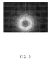
- FIG.2 is a sectional view of the light source device including a lens of the LED lamp of FIG. 1 .
- FIG. 3 is an isometric and schematic view of the lens of FIG. 2 .
- FIG. 4 is a sectional view taken long the line IV-IV of the lens of FIG. 3 .
- FIG. 5 shows exemplary light paths of the light source device of FIG. 2 .
- FIG. 6 shows a diagram of an illumination distribution of light emitted from the light source device of FIG. 2 in a first example.
- FIG. 7 shows a diagram of an illumination distribution of light emitted from a light source device in a second example.
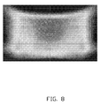
- FIG. 8 shows a diagram of an illumination distribution of light emitted from a light source device in a third example.
- FIG. 9 is a diagram of an illumination distribution of light emitted from a light source device in a fourth example.
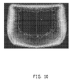
- FIG. 10 is a schematic view of an LED lamp including an LED, according to the related art.
- FIG. 11 is a diagram of an illumination distribution of light emitted from the LED of FIG. 10 .
- an LED lamp 50 is shown.
- the LED lamp 50 is a street lamp.
- the LED lamp 50 includes a pole 52, a fixing arm 54, a light cover 58, and a light source device 40.
- the fixing arm 54 extends from the pole 52.
- the light cover 58 is mounted on a distal end 54a of the fixing arm 54 away from the pole 52.
- the light source device 40 is received in the light cover 58.
- the light source device 40 includes a lens 20 and an LED 30.
- the LED 30 is received in the lens 20.
- the lens 20 may be made of a transparent material, such as plastic or glass.
- the plastic is selected from the group consisting of polymethyl methacrylate (PMMA), polycarbonate (PC), and silicone.
- the lens 20 includes a bottom surface 22, a light receiving surface 24, a light emitting surface 26, four first side surfaces 27, and four second side surfaces 28.
- the light receiving surface 24 is positioned between the bottom surface 22 and the light emitting surface 26.
- the light emitting surface 26 is connected to the bottom surface 22 at four sides of the bottom surface 22 by the four first side surfaces 27.
- the light receiving surface 24 is connected to the bottom surface 22 at four sides of the light receiving surface 24 by the four second side surfaces 28.
- a receiving space 29 is cooperatively defined by the light receiving surface 24 and the four second side surfaces 28.
- the LED 30 is received in the receiving space 29 and emits light towards the light receiving surface 24.
- an illumination distribution of the light emitted from the light emitting surface 26 is substantially rectangle and asymmetric relative to a center of the LED 30.
- the light receiving surface 24 satisfies an equation (1): , wherein N 1 and N 2 are natural numbers, and a i and b j are aspheric coefficients.
- N 2 1
- a 1 and b 1 are key aspheric coefficients and satisfy the following formulas: -0.5 ⁇ a 1 ⁇ 0, -0.7 ⁇ b 1 ⁇ 0.
- N 2 ⁇ 2 a 1 , b 1 , and b 2 are key aspheric coefficients and satisfy the following formulas: -0.5 ⁇ a 1 ⁇ 0, -0.7 ⁇ b 1 ⁇ 0, -0.3 ⁇ b 2 ⁇ 0.
- N 1 and N 2 are natural numbers
- c i and d j are aspheric coefficients.
- N 2 1
- c 1 and d 1 are key aspheric coefficients and satisfy the following formulas: -0.3 ⁇ c 1 ⁇ 0, 0 ⁇ d 1 ⁇ 0.6.
- c 1 , d 1 , and d 2 are key aspheric coefficients and satisfy the following formulas: -0.3 ⁇ c 1 ⁇ 0,0 ⁇ d 1 ⁇ 0.6, -0.2 ⁇ d 2 ⁇ 0.
- a thickness of the lens 20 is 5.75 millimeters, i.e., a height of the lens 20 measured from a top portion 24a of the light receiving surface 24 to a top portion 26a of the light emitting surface 26 (see FIG.
- FIG. 7 the illumination distribution of light emitted from the light source device 40 is shown in FIG. 7 . As illustrated in FIG. 7 , the illumination distribution of light emitted from the light source device 40 is uniform.
Landscapes
- Physics & Mathematics (AREA)
- General Physics & Mathematics (AREA)
- Optics & Photonics (AREA)
- Engineering & Computer Science (AREA)
- General Engineering & Computer Science (AREA)
- Lenses (AREA)
- Non-Portable Lighting Devices Or Systems Thereof (AREA)
Applications Claiming Priority (1)
| Application Number | Priority Date | Filing Date | Title |
|---|---|---|---|
| CN200910309538A CN102062883B (zh) | 2009-11-11 | 2009-11-11 | 透镜及采用该透镜的照明装置及路灯 |
Publications (1)
| Publication Number | Publication Date |
|---|---|
| EP2322973A1 true EP2322973A1 (de) | 2011-05-18 |
Family
ID=43587367
Family Applications (1)
| Application Number | Title | Priority Date | Filing Date |
|---|---|---|---|
| EP10189459A Withdrawn EP2322973A1 (de) | 2009-11-11 | 2010-10-29 | Linse und lichtemittierende Diodenlampe damit |
Country Status (3)
| Country | Link |
|---|---|
| EP (1) | EP2322973A1 (de) |
| KR (1) | KR101185287B1 (de) |
| CN (1) | CN102062883B (de) |
Cited By (1)
| Publication number | Priority date | Publication date | Assignee | Title |
|---|---|---|---|---|
| WO2012090108A1 (en) * | 2010-12-30 | 2012-07-05 | Koninklijke Philips Electronics N.V. | A lens and a lighting apparatus comprising such a lens. |
Families Citing this family (5)
| Publication number | Priority date | Publication date | Assignee | Title |
|---|---|---|---|---|
| KR101531390B1 (ko) * | 2011-08-30 | 2015-07-06 | 삼성전자주식회사 | 비대칭 형상의 렌즈 및 이를 포함하는 가로등 |
| KR101471609B1 (ko) * | 2012-11-20 | 2014-12-12 | 주식회사 이엘 | 등기구용 복합 굴절 렌즈 및 이를 갖는 가로등 장치 |
| CN104570305B (zh) * | 2013-10-24 | 2017-11-14 | 清华大学 | 自由曲面透镜及含有该自由曲面透镜的成像系统 |
| KR102005347B1 (ko) * | 2017-07-21 | 2019-10-01 | (주)선린 | 낮은 가로등용 엘이디 조명모듈 및 엘이디 렌즈 |
| KR101869025B1 (ko) | 2017-11-29 | 2018-06-19 | 주식회사 금경라이팅 | 멀티렌즈가 구비된 엘이디 조명장치 |
Citations (4)
| Publication number | Priority date | Publication date | Assignee | Title |
|---|---|---|---|---|
| CN101382252A (zh) * | 2008-10-22 | 2009-03-11 | 东莞市明家电子工业有限公司 | 大功率led透镜 |
| CN101482652A (zh) * | 2009-02-12 | 2009-07-15 | 复旦大学 | 一种针对点光源配光透镜的设计方法 |
| CN101487579A (zh) * | 2008-01-17 | 2009-07-22 | 宁波燎原灯具股份有限公司 | 适用于led路灯的透镜系统 |
| CN101571259A (zh) * | 2008-04-29 | 2009-11-04 | 汪正林 | Led透镜 |
Family Cites Families (7)
| Publication number | Priority date | Publication date | Assignee | Title |
|---|---|---|---|---|
| US5909322A (en) * | 1997-11-05 | 1999-06-01 | Eastman Kodak Company | Magnifier lens |
| KR100682563B1 (ko) * | 1999-07-26 | 2007-02-15 | 라보 스피아 가부시키가이샤 | 벌크형 렌즈, 발광체, 조명 기구 및 광 정보 시스템 |
| US6547423B2 (en) | 2000-12-22 | 2003-04-15 | Koninklijke Phillips Electronics N.V. | LED collimation optics with improved performance and reduced size |
| JP2008270144A (ja) | 2007-03-22 | 2008-11-06 | Furukawa Electric Co Ltd:The | ライトボックス |
| CN201228918Y (zh) * | 2008-07-12 | 2009-04-29 | 鹤山丽得电子实业有限公司 | 一种led路灯配光透镜 |
| CN201255364Y (zh) * | 2008-09-03 | 2009-06-10 | 浙江名芯半导体科技有限公司 | Led灯道路照明用透镜 |
| CN110148757A (zh) | 2017-06-28 | 2019-08-20 | 湖南妙盛汽车电源有限公司 | 一种热导锂离子电池 |
-
2009
- 2009-11-11 CN CN200910309538A patent/CN102062883B/zh not_active Expired - Fee Related
-
2010
- 2010-10-20 KR KR1020100102465A patent/KR101185287B1/ko not_active Expired - Fee Related
- 2010-10-29 EP EP10189459A patent/EP2322973A1/de not_active Withdrawn
Patent Citations (4)
| Publication number | Priority date | Publication date | Assignee | Title |
|---|---|---|---|---|
| CN101487579A (zh) * | 2008-01-17 | 2009-07-22 | 宁波燎原灯具股份有限公司 | 适用于led路灯的透镜系统 |
| CN101571259A (zh) * | 2008-04-29 | 2009-11-04 | 汪正林 | Led透镜 |
| CN101382252A (zh) * | 2008-10-22 | 2009-03-11 | 东莞市明家电子工业有限公司 | 大功率led透镜 |
| CN101482652A (zh) * | 2009-02-12 | 2009-07-15 | 复旦大学 | 一种针对点光源配光透镜的设计方法 |
Cited By (1)
| Publication number | Priority date | Publication date | Assignee | Title |
|---|---|---|---|---|
| WO2012090108A1 (en) * | 2010-12-30 | 2012-07-05 | Koninklijke Philips Electronics N.V. | A lens and a lighting apparatus comprising such a lens. |
Also Published As
| Publication number | Publication date |
|---|---|
| CN102062883B (zh) | 2012-09-19 |
| KR20110052458A (ko) | 2011-05-18 |
| KR101185287B1 (ko) | 2012-09-21 |
| CN102062883A (zh) | 2011-05-18 |
Similar Documents
| Publication | Publication Date | Title |
|---|---|---|
| US9169980B2 (en) | Lighting device and display device | |
| US9200777B2 (en) | Optical element and illumination device using the same | |
| EP1998103A1 (de) | Lichtquellenanordnung und Rückbeleuchtungsmodul damit | |
| US7946746B2 (en) | Surface light source device | |
| EP1779153A4 (de) | Diffusor für licht aus einer lichtquellengruppe und displays damit | |
| US8979328B2 (en) | Optical lens and lighting device having same | |
| EP1918739A3 (de) | Optische Linsenplatte, Rückbeleuchtungseinheit und Anzeigevorrichtung | |
| US9465205B2 (en) | Optical lens and backlight module incorporating the same | |
| TW200716914A (en) | Illumination device | |
| ATE408785T1 (de) | Leuchtkörper | |
| TWI289712B (en) | Light emitting panel assemblies | |
| US20140177235A1 (en) | Optical lens and lighting device having the same | |
| US20160348873A1 (en) | Lens, light emitting device and backlight module | |
| CN101418930A (zh) | 发光二极管面光源装置 | |
| AU2013326308B2 (en) | Improved LCD backlight display | |
| US8905596B2 (en) | Optical lens and lighting device having same | |
| KR101185287B1 (ko) | 렌즈, 이 렌즈를 사용하는 조명장치 및 가로등 | |
| KR101189652B1 (ko) | Led용 조명렌즈 및 이를 이용한 어레이 타입 조명렌즈 | |
| US20050052871A1 (en) | Light-emitting diode and backlight system using the same | |
| US20060120107A1 (en) | LED backlight module | |
| US10133029B2 (en) | Lens and light source apparatus | |
| CN109425926B (zh) | 具有导光结构的电子装置 | |
| US7175328B2 (en) | Piezoelectric light-emitting diode and backlight system using the same | |
| JP3146186U (ja) | 非球面広照射角度発光ダイオードの光学レンズ及びそれを構成する発光ダイオード構成材 | |
| US20150016118A1 (en) | Lens with different layers and led unit using the same |
Legal Events
| Date | Code | Title | Description |
|---|---|---|---|
| PUAI | Public reference made under article 153(3) epc to a published international application that has entered the european phase |
Free format text: ORIGINAL CODE: 0009012 |
|
| AK | Designated contracting states |
Kind code of ref document: A1 Designated state(s): AL AT BE BG CH CY CZ DE DK EE ES FI FR GB GR HR HU IE IS IT LI LT LU LV MC MK MT NL NO PL PT RO RS SE SI SK SM TR |
|
| AX | Request for extension of the european patent |
Extension state: BA ME |
|
| 17P | Request for examination filed |
Effective date: 20111114 |
|
| 17Q | First examination report despatched |
Effective date: 20120928 |
|
| STAA | Information on the status of an ep patent application or granted ep patent |
Free format text: STATUS: THE APPLICATION IS DEEMED TO BE WITHDRAWN |
|
| 18D | Application deemed to be withdrawn |
Effective date: 20130209 |