EP2323210A1 - Système de pile à combustible - Google Patents
Système de pile à combustible Download PDFInfo
- Publication number
- EP2323210A1 EP2323210A1 EP11150854A EP11150854A EP2323210A1 EP 2323210 A1 EP2323210 A1 EP 2323210A1 EP 11150854 A EP11150854 A EP 11150854A EP 11150854 A EP11150854 A EP 11150854A EP 2323210 A1 EP2323210 A1 EP 2323210A1
- Authority
- EP
- European Patent Office
- Prior art keywords
- fuel
- fuel cell
- module
- cell system
- oxidizer
- Prior art date
- Legal status (The legal status is an assumption and is not a legal conclusion. Google has not performed a legal analysis and makes no representation as to the accuracy of the status listed.)
- Granted
Links
Images


Classifications
-
- H—ELECTRICITY
- H01—ELECTRIC ELEMENTS
- H01M—PROCESSES OR MEANS, e.g. BATTERIES, FOR THE DIRECT CONVERSION OF CHEMICAL ENERGY INTO ELECTRICAL ENERGY
- H01M8/00—Fuel cells; Manufacture thereof
- H01M8/04—Auxiliary arrangements, e.g. for control of pressure or for circulation of fluids
- H01M8/04082—Arrangements for control of reactant parameters, e.g. pressure or concentration
- H01M8/04201—Reactant storage and supply, e.g. means for feeding, pipes
-
- H—ELECTRICITY
- H01—ELECTRIC ELEMENTS
- H01M—PROCESSES OR MEANS, e.g. BATTERIES, FOR THE DIRECT CONVERSION OF CHEMICAL ENERGY INTO ELECTRICAL ENERGY
- H01M8/00—Fuel cells; Manufacture thereof
- H01M8/04—Auxiliary arrangements, e.g. for control of pressure or for circulation of fluids
- H01M8/04082—Arrangements for control of reactant parameters, e.g. pressure or concentration
- H01M8/04089—Arrangements for control of reactant parameters, e.g. pressure or concentration of gaseous reactants
- H01M8/04104—Regulation of differential pressures
-
- H—ELECTRICITY
- H01—ELECTRIC ELEMENTS
- H01M—PROCESSES OR MEANS, e.g. BATTERIES, FOR THE DIRECT CONVERSION OF CHEMICAL ENERGY INTO ELECTRICAL ENERGY
- H01M8/00—Fuel cells; Manufacture thereof
- H01M8/06—Combination of fuel cells with means for production of reactants or for treatment of residues
- H01M8/0606—Combination of fuel cells with means for production of reactants or for treatment of residues with means for production of gaseous reactants
- H01M8/065—Combination of fuel cells with means for production of reactants or for treatment of residues with means for production of gaseous reactants by dissolution of metals or alloys; by dehydriding metallic substances
-
- H—ELECTRICITY
- H01—ELECTRIC ELEMENTS
- H01M—PROCESSES OR MEANS, e.g. BATTERIES, FOR THE DIRECT CONVERSION OF CHEMICAL ENERGY INTO ELECTRICAL ENERGY
- H01M8/00—Fuel cells; Manufacture thereof
- H01M8/24—Grouping of fuel cells, e.g. stacking of fuel cells
- H01M8/2465—Details of groupings of fuel cells
- H01M8/247—Arrangements for tightening a stack, for accommodation of a stack in a tank or for assembling different tanks
- H01M8/2475—Enclosures, casings or containers of fuel cell stacks
-
- H—ELECTRICITY
- H01—ELECTRIC ELEMENTS
- H01M—PROCESSES OR MEANS, e.g. BATTERIES, FOR THE DIRECT CONVERSION OF CHEMICAL ENERGY INTO ELECTRICAL ENERGY
- H01M8/00—Fuel cells; Manufacture thereof
- H01M8/24—Grouping of fuel cells, e.g. stacking of fuel cells
- H01M8/2465—Details of groupings of fuel cells
- H01M8/2484—Details of groupings of fuel cells characterised by external manifolds
-
- H—ELECTRICITY
- H01—ELECTRIC ELEMENTS
- H01M—PROCESSES OR MEANS, e.g. BATTERIES, FOR THE DIRECT CONVERSION OF CHEMICAL ENERGY INTO ELECTRICAL ENERGY
- H01M8/00—Fuel cells; Manufacture thereof
- H01M8/24—Grouping of fuel cells, e.g. stacking of fuel cells
- H01M8/249—Grouping of fuel cells, e.g. stacking of fuel cells comprising two or more groupings of fuel cells, e.g. modular assemblies
-
- H—ELECTRICITY
- H01—ELECTRIC ELEMENTS
- H01M—PROCESSES OR MEANS, e.g. BATTERIES, FOR THE DIRECT CONVERSION OF CHEMICAL ENERGY INTO ELECTRICAL ENERGY
- H01M8/00—Fuel cells; Manufacture thereof
- H01M8/10—Fuel cells with solid electrolytes
- H01M2008/1095—Fuel cells with polymeric electrolytes
-
- Y—GENERAL TAGGING OF NEW TECHNOLOGICAL DEVELOPMENTS; GENERAL TAGGING OF CROSS-SECTIONAL TECHNOLOGIES SPANNING OVER SEVERAL SECTIONS OF THE IPC; TECHNICAL SUBJECTS COVERED BY FORMER USPC CROSS-REFERENCE ART COLLECTIONS [XRACs] AND DIGESTS
- Y02—TECHNOLOGIES OR APPLICATIONS FOR MITIGATION OR ADAPTATION AGAINST CLIMATE CHANGE
- Y02E—REDUCTION OF GREENHOUSE GAS [GHG] EMISSIONS, RELATED TO ENERGY GENERATION, TRANSMISSION OR DISTRIBUTION
- Y02E60/00—Enabling technologies; Technologies with a potential or indirect contribution to GHG emissions mitigation
- Y02E60/30—Hydrogen technology
- Y02E60/50—Fuel cells
Definitions
- the invention relates to a fuel cell system, comprising a fuel cell device with one or more fuel cell blocks, in which chemical energy can be converted into electrical energy, an oxidizer supply device for the fuel cell device, a fuel supply device for the fuel cell device, and a control device.
- Fuel cell systems comprising a fuel cell device with one or more fuel cell blocks in which chemical energy is convertible into electrical energy, an oxidizer supply device for the fuel cell device, a fuel supply device for the fuel cell device, and a control device are known, for example from US Pat DE 101 27 600 A1 or C2 or the DE 101 27 599 A1 known.
- a modular power supply system which comprises an electrolysis module with a first connection set and a power module with a second connection set.
- the first connection set set is designed for communication with a water supply and / or a hydrogen storage device and / or the power module.
- the electrolysis module and / or the power module are removable separately from the modular power system.
- a portable power generation system which has a fuel cell for generating electrical energy.
- the invention has for its object to provide a flexible usable fuel cell system.
- the fuel cell device, the oxidizer supply device, the fuel supply device and a cooling device which is assigned to the fuel cell device, each designed as a module, wherein in a module, the functional components of the respective Means are arranged, the corresponding module forms a unit which can be positioned as a whole, and the corresponding module has a communication interface with terminals.
- modules can be produced, adjusted and positioned separately. Due to the modular structure of the fuel cell system, this can be flexibly integrated into an application. In particular, an adaptation to geometric conditions is possible.
- each module a defined interface for communication with the outside world or other modules regarding mass transfer (via material flows) and / or energy exchange and / or signal exchange is provided.
- the operating parameters with regard to material flows, electrical currents and signal currents can be adjusted separately and also optimized for each module.
- safety-relevant components can be formed separately.
- For the fuel guide is then only the fuel supply device module and the fuel cell device module relevant. The other modules are then no longer relevant to safety.
- the fuel cell system according to the invention can be in the DE 101 27 599 A1 , of the DE 101 27 600 A1 and DE 101 27 600 C2 perform the procedure described. Furthermore, the fuel cell system according to the invention can be formed as described in these publications. Reference is expressly made to these documents.
- a corresponding module has a housing in which the functional components are arranged.
- the module can be formed as a unit.
- a defined interface and in particular a defined communication interface can be arranged on the housing.
- the functional components are protected in the housing.
- the housing is at least partially made of a transparent material so that gauges such as pressure gauges can be read.
- connection or connections are arranged on the housing, via which modules can communicate with one another or with corresponding devices.
- the housing is closed. This protects the functional components located in the housing.
- the housing is gastight, in particular in the case of the fuel cell device module and the fuel supply device module. This prevents fuel from escaping at undefined locations.
- the system can be provided with a safety ventilation directly to the environment.
- connections include in particular material connections, signal connections and electrical power connections. Substances can be exchanged via the substance connections. For example, fuel is coupled out via a coupling connection of the fuel supply device module and can be coupled into this fuel via a fuel injection connection of the fuel cell device. Control signals can be injected via signal connections or control signals can be decoupled. Electrical power can be coupled in via electrical power connections or (in the case of the fuel cell device) decoupled.
- the fuel cell assembly module has oxidizer and fuel attachments and a port for coupling electrical power.
- the fuel cell device module has at least one signal connection for coupling control signals.
- control signals can be coupled in via such a connection in order to open and close a shut-off valve via which unused fuel can be discharged.
- the fuel supply module has at least one fuel port for coupling fuel. About this fuel connection, a connection to the fuel cell device can be produced.
- the fuel supply device module has at least one signal connection.
- the oxidizer supply module has at least one oxidizer port for coupling oxidizer. It can thereby decouple air with atmospheric oxygen as an oxidizer. This connection can be used to connect to a fuel cell device.
- the oxidizer supply device module has at least one signal connection via which, in particular, control signals can be coupled in.
- modules are connected via lines.
- the modules can first be separated and positioned independently of each other on an application.
- the necessary communication connections with regard to material transport, supply of electrical power and with respect to control signals are then produced subsequently according to the geometric conditions. This results in a flexible structure, wherein the fuel cell system according to the invention is formed by subsystems.
- the lines of the module (s) are separate elements.
- one or more fuel reservoirs are integrated into the fuel supply module. For example, if a fuel storage is deflated, then the fuel supply module is replaced as a whole.
- At least one fuel storage is provided, which is coupled to the fuel supply device and in particular forms an external element with respect to a fuel supply device module.
- a fuel storage module may be coupled to a fuel supply module. If a fuel storage is drained, then a corresponding fuel storage module can be easily replaced.
- the at least one fuel storage or the at least one fuel storage module is designed as a structural element of the fuel cell system or an application.
- the energy supply device of the application which is formed with the aid of the fuel cell system, can save space.
- the at least one fuel storage or the at least one fuel storage module is or comprises a metal hydride storage.
- a metal hydride storage hydrogen is not stored as free gas, but in bound form. For example, by heating, hydrogen can be driven out of such a metal hydride storage. It does not occur the security problems as in the hydrogen storage in a pressure tank.
- a metal hydride reservoir is a solid element that can be used as a structural element and, for example, as a structural element for an application.
- the at least one fuel storage is formed by means of one or more extruded profiles.
- Corresponding metal hydride reservoirs are available, for example, under the name MH Hydrogene Storage Tank from SUMITOMO PRECISION PRODUCTS CO., LTD., Japan.
- the fuel cell device is associated with a cooling device. As a result, they can be operated with optimized efficiency.
- the cooling device is arranged and designed such that at least one fuel reservoir can be acted upon by waste-heat air.
- the waste heat air can then be used to expel hydrogen, for example from a metal hydride storage.
- the efficiency of the fuel cell system can be improved.
- the cooling device it is basically possible for the cooling device to be integrated with the fuel cell device in a fuel cell module. It is also possible that the cooling device is designed as a module.
- the cooling device module then has at least one waste-heat air connection.
- waste heat can be decoupled, for example, to supply them to a metal hydride storage.
- the cooling device module has at least one signal connection.
- the corresponding cooling device can then be controlled via control signals in such a way that an optimum cooling effect results.
- control device is designed as a module.
- the control device then forms a separate component of the fuel cell system.
- a central control device is realized.
- control device by means of the control device a sequence control is formed, which transmits preset control signals. There is no control of the fuel supply and Oxidatorzu Adjustment to the fuel cell device, but at most one control.
- a corresponding method is in the DE 101 27 600 A1 described with reference to this document.
- control device It is advantageous if electrical consumers of the fuel cell system are supplied with electrical energy via the control device.
- the control device then provides a defined interface, via which the corresponding modules can obtain the electrical energy in the required form.
- a module has, for example, a block-shaped plastic housing. In such a block-shaped plastic housing can be formed via a hole a cloth guide.
- the pressure outputable fuel is set for the fuel supply device.
- the fuel cell device 12 is the fuel cell core device of the fuel cell system 10. Further, the fuel cell system 10 comprises a fuel supply device 16, by means of which the fuel cell or blocks 14 of the Fuel cell device 12 can be supplied with fuel.
- the fuel cell system 10 includes an oxidizer supply device 18 for the fuel cell device 12, by means of which the fuel cell or blocks 14 oxidizer can be provided.
- a control device 20 is provided for controlling the fuel cell system 10.
- the one or more fuel cell blocks 14 may be associated with a cooling device 22.
- the fuel cells of the fuel cell block or blocks 14 are, in particular, polymer membrane fuel cells (PEFC), in which the electrolyte is formed by a proton-conducting membrane.
- PEFC polymer membrane fuel cells
- the membrane is also catalyst support for the anodic and cathodic electrocatalysts and serves as a separator for the gaseous reactants.
- hydrogen is used and as an oxidizer oxygen and in particular atmospheric oxygen.
- the fuel cell device 12 is then fed air with oxygen in the air as the oxidizer.
- the fuel cell system 10 is modularly constructed with a fuel cell device module 26, a fuel supply module 28, and an oxidizer supply module 30.
- controller module 32 which comprises the controller 20.
- the cooling device 22 is integrated in a cooling device module 34.
- a fuel storage module 36 is provided.
- fuel storage it is also possible for fuel storage to be integrated with the fuel supply module 28.
- the oxidizer supply module 30 has a closed housing 38.
- the housing may be designed gas-tight.
- the housing is transparent.
- One possible material is Plexiglas.
- the oxidizer supply module 30 is provided with a communication interface 40 having an output port 42 through which the oxidizer can be coupled.
- air can be coupled out as oxidizer carrier with atmospheric oxygen as oxidizer.
- an electrical connection 44 is provided, via which electrical energy can be coupled into the oxidizer supply device module 30 for provision to electrical consumers of this module.
- a signal connection 46 may be provided for the coupling of control signals.
- the respective terminals 42, 44 and 46 are disposed on the housing 38.
- an air compressor 48 is arranged in the housing 38. This is preceded by a filter 50.
- the housing 38 has one or more air supply openings 52, via which air can be supplied to the air compressor 48, wherein the filter 50 must be passed through the supplied air.
- an air conveyor and cooler 54 is arranged, which in particular is driven by an electric motor.
- a water separator 56 is connected downstream. Via this water separator 56 can be dehumidified by the oxidizer supply device module 30 performed air.
- the water separator 56 is associated with an actuating element 58, which is in communication with an outlet, can be drained via the water.
- the oxidizer supply module 30 includes a pressure switch 60 and a pressure gauge 62.
- a pressure switch 60 By means of the pressure switch 60 a certain air flow of the air compressor 48 can be checked. This air flow is fixed by an actuator (such as the adjustment valve 118). The air flow can be decoupled at the output port 42.
- an adjusting device can also be connected directly to the module 30 and / or only temporarily connected.
- the oxidizer supply module 38 forms a unit that can be positioned as a whole.
- Electrical loads of the oxidizer utility module 30 are supplied via the controller module 32 with electrical energy (coupled to the electrical terminal 44).
- the fuel supply module 28 includes a housing 64 in which the functional components of the fuel supply 16 are disposed.
- the housing 64 is in particular closed and gas-tight. It is preferably provided that guides for Fuel within the fuel supply device module 28 are formed tube-free.
- the housing 64 is formed by means of a Plexiglas block and the corresponding flow guides are formed by bores in the Plexiglas block. Thereby, a type of bus system is provided for the flow guidance of the fuel within the fuel supply module 28.
- fuel reservoirs are disposed outside of the fuel supply module 28.
- a separate fuel storage module 36 is provided.
- a connection 66 is provided for the coupling of fuel.
- This port 66 is in fluid communication with a fuel guide 68 within the housing 64.
- a safety valve 70 is coupled to this fuel guide 68.
- a pressure switch 72 is provided, via which the pressure of the guided inside the housing 64 fuel (in particular hydrogen) can be checked.
- the pressure switch 72 is followed by a Druckminderer- / adjustment device 74 with pressure indication.
- a flame arrester 76 is provided.
- a bleed valve 78 is disposed in the fuel guide 68. About the discharge valve 78 can be decoupled in the housing 64 befindaji gaseous fuel.
- Another pressure switch 82 can be used to check the pressure of fuel that can be coupled out at a connection 84. About a pressure gauge 86, this pressure can be displayed.
- the fuel supply module 28 has a communication interface that includes the ports 66 and 84. Furthermore, a control signal terminal 88 may be provided. For the coupling of electrical energy for providing to electrical consumers of the fuel supply device module 28 may be provided an electrical connection (in FIG. 1 Not shown).
- the fuel supply module 28 forms a unit which is positionable as a whole.
- the fuel storage module 36 has an interface 90, via which fuel can be decoupled and in particular the fuel supply device module 28 can be fed.
- the fuel storage module 36 has one or more fuel storage 92, in which, for example, hydrogen is stored in gaseous form.
- One or more metal hydride reservoirs 94 (FIG. FIG. 5 ) be provided. Such a metal hydride reservoir 94 is formed in particular by means of an extruded profile 96.
- Such a metal hydride reservoir 94 may be a structural element of the fuel cell system 10 or an application. Since the Metallhydrid Uber 94 is mechanically resilient with its extruded profile 96, it can also take a supporting function, for example in a vehicle to support vehicle parts or to hold the fuel cell system 10 with its modules or to hold individual modules of the fuel cell system 10.
- the fuel storage module 36 is particularly arranged and adapted to be interchangeable. After emptying, it may then be removed and a new fuel storage module 36 may be employed with filled fuel storage 92 and filled fuel storage 92, respectively.
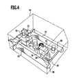
- fuel storage 98 into the housing 64 of the fuel supply module 28 are integrated.
- fuel storage module 36 is a combination module formed, which includes the fuel supply device 16 and the or the fuel storage.
- Such a fuel supply module has in principle the same functional components as described with reference to the fuel supply module 28. It will therefore be in FIG. 4 the same reference numerals are used.
- the fuel which can be coupled out at the port 84, is set to a fixed pressure value predetermined via the pressure switch 82. Via the pressure display 86, this pressure value is displayed.
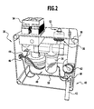
- the fuel cell device module 26 has a housing 100 (FIG. FIGS. 1 and 3 ).
- the housing is formed in particular closed with defined cooling air. For example, it is transparent.
- the fuel cell or blocks 14 are arranged. Further, in the housing 100, a fuel discharge line 102 is arranged. At this discharge line 102 sits a time-controllable (blocking) valve 104. This is in particular an electromagnetic valve. Via a pressure display 106, the pressure is displayed.
- an adjustment valve 108 may be provided, with which the pressure drop at the opening of the valve 104 can be adjusted.
- the discharge line 102 opens into an outlet port 110 through which unused fuel can be discharged.
- an oxidant discharge line 112 and in particular air discharge line is arranged in the housing 100. This opens into an outlet port 114. At the discharge line 112 is a pressure indicator 116th coupled. Further, an adjustment valve 118 is provided to adjust the volume flow of the discharged air can.
- a temperature switch 119 may be provided.
- the fuel cell device module 26 has a control signal connection 120, via which control signals can be coupled.
- the valve 104 (which is a check valve) can be activated.
- This check valve 104 is controlled to be either open or closed. It is clocked controlled and can be opened so clocked that is provided for a fuel relaxation of the fuel cell block 14 ago.
- a communication interface for the fuel cell device module 26 is formed.
- the fuel cell assembly module 26 forms a unit which is positionable as a whole separate from the other modules.
- a cooling device may be integrated into the fuel cell device module 26.
- a separate cooling device module 34 which is coupleable to the fuel cell device module 26.
- a cooling device module 34 comprises one or more fans 122, via which the fuel cell block or blocks 14 can be acted upon by an air flow 124 for cooling.
- the cooling device module 34 has an electrical connection via which the corresponding energy for operating the fan or fans 122 can be coupled in (not shown in the drawing).
- a control signal connection 126 may be provided.
- the cooling device module 34 has one or more connections 128 for removing waste heat air.
- the waste heat air can then be conducted to a metal hydride storage 94 via corresponding connecting lines in order to activate it for releasing hydrogen.
- a connection is via a line which is coupled to the port 66 of the fuel supply module 28 and coupled to the interface 90 of the fuel storage module 36.
- the fuel supply module 28 communicates with the fuel cell assembly module 26 via its fuel output port 84. At an input port 132 of the fuel cell assembly module 26 fuel can be coupled. To guide the fuel between the fuel supply module 28 and the fuel cell module 26, a line 134 is provided, which is a separate element from the two modules. The cable is chosen according to the position and distance of the two modules.
- Air with atmospheric oxygen as the oxidizer can be coupled out at the output terminal 42 of the oxidizer supply module 30.
- the fuel cell device module 26 has an input port 136 through which air can be coupled.
- the ports 42 and 136 may be connected via a conduit 138, which conduit 138 is an element separate from the oxidizer supply module 30 and the fuel cell assembly module 26.
- the controller module 32 also forms a unit which as a whole is positionable independently of the other modules. It has corresponding connections 140a, 140b, 140c, 140d, via which control signals can be coupled out to modules which can be acted upon by control signals. Control signal lines 142a and so forth can be coupled to the ports to transmit the control signals.
- controller module 32 has one or more electrical energy connectors 144. From these electrical energy can be decoupled and coupled via corresponding services to corresponding power terminals of the modules. As a result, electrical consumers of the corresponding modules can then be supplied with energy.
- the fuel cell system 10 functions to firmly set feed parameters of fuel (via the fuel supply module 28) and oxidizer (via the oxidizer supply module 30), with the pressure of the fuel supplied to a fuel cell block 14 being set on the supply side , a continuous discharge of hydrogen from a fuel cell block 14 is inhibited, and an amount of fuel supplied to a fuel cell block 14 is controlled by the power consumption of an (external) load.
- control device 20 by means of the control device 20 a sequence control is formed, which transmits preset control signals.
- a control of the supply is not necessary in the described method implementation.
- a fuel cell system composed of at least positionable subsystems, namely the fuel cell assembly module 26, the fuel supply module 28, the oxidizer supply module 30, and the controller module 32.
- the modules have defined interfaces for communication with other modules.
- the modules are separated. In them, the corresponding functional components are fixed, so that a module can be positioned as a unit. Connecting elements and in particular lines connect together cooperating modules.
- Per module the operating parameters and in particular material flows, electrical currents and signal currents can be set separately.
- the modules can be manufactured separately.
- a safety-relevant aspect is the fuel guide in the fuel cell system 10. Due to the modular design but not the fuel cell system 10 as a whole is concerned, but only the modules in which fuel is fed, ie the fuel supply device module 28 (possibly also the fuel storage module 36) and fuel cell assembly module 26 and conduit 134. Within the fuel cell assembly module 26 and the fuel supply module 28, the fuel can, for example, lead into bores, which are formed by recesses in a solid material. There are no pipes necessary that can leak. The corresponding modules 26 and 28 can also be made gastight while the entire fuel cell system 10 no longer has to be gas-tight.
- modules 26 and 28 can be provided with a safety ventilation to the environment outside the entire system.
- the cables between modules are independent of the modules. They can be connected to the modules via safety couplings, for example, if mass transfer lines are provided.
- modules can be replaced as a whole.
- a fuel supply module and / or a fuel storage module is replaced as a whole.
- a fuel storage or fuel storage module may also form a structural element of an application.
- a metal hydride storage can be used as a supporting structural element.
- the necessary fuel is carried on board.
- the necessary oxidizer comes from the ambient air.
- a simple fuel cell system 10 is provided, which in particular is air-cooled. It can be flexibly integrated into an application due to its modular design. The company does not have to be supervised.
Landscapes
- Life Sciences & Earth Sciences (AREA)
- Engineering & Computer Science (AREA)
- Manufacturing & Machinery (AREA)
- Sustainable Development (AREA)
- Sustainable Energy (AREA)
- Chemical & Material Sciences (AREA)
- Chemical Kinetics & Catalysis (AREA)
- Electrochemistry (AREA)
- General Chemical & Material Sciences (AREA)
- Fuel Cell (AREA)
Applications Claiming Priority (3)
| Application Number | Priority Date | Filing Date | Title |
|---|---|---|---|
| DE102004046004 | 2004-09-17 | ||
| DE102004059776A DE102004059776A1 (de) | 2004-09-17 | 2004-12-07 | Brennstoffzellensystem |
| EP05782441A EP1787348B1 (fr) | 2004-09-17 | 2005-09-06 | Systeme de piles a combustible |
Related Parent Applications (1)
| Application Number | Title | Priority Date | Filing Date |
|---|---|---|---|
| EP05782441.9 Division | 2005-09-06 |
Publications (2)
| Publication Number | Publication Date |
|---|---|
| EP2323210A1 true EP2323210A1 (fr) | 2011-05-18 |
| EP2323210B1 EP2323210B1 (fr) | 2012-07-25 |
Family
ID=35115895
Family Applications (2)
| Application Number | Title | Priority Date | Filing Date |
|---|---|---|---|
| EP11150854A Expired - Lifetime EP2323210B1 (fr) | 2004-09-17 | 2005-09-06 | Système de pile à combustible |
| EP05782441A Expired - Lifetime EP1787348B1 (fr) | 2004-09-17 | 2005-09-06 | Systeme de piles a combustible |
Family Applications After (1)
| Application Number | Title | Priority Date | Filing Date |
|---|---|---|---|
| EP05782441A Expired - Lifetime EP1787348B1 (fr) | 2004-09-17 | 2005-09-06 | Systeme de piles a combustible |
Country Status (5)
| Country | Link |
|---|---|
| US (1) | US20070237996A1 (fr) |
| EP (2) | EP2323210B1 (fr) |
| AT (1) | ATE500629T1 (fr) |
| DE (3) | DE102004059776A1 (fr) |
| WO (1) | WO2006032359A2 (fr) |
Families Citing this family (18)
| Publication number | Priority date | Publication date | Assignee | Title |
|---|---|---|---|---|
| DE102006034816B4 (de) | 2006-07-27 | 2011-02-24 | Airbus Operations Gmbh | Brennstoffzellen-Kühlsystem für Luftfahrzeuge und dessen Verwendung |
| DE102007028298A1 (de) * | 2007-06-20 | 2008-12-24 | Daimler Ag | Gekapselte Abscheiderbaueinheit zur Integration in einer Gasversorgung eines Brennstoffzellensystems |
| DE102007058717A1 (de) | 2007-12-06 | 2008-06-12 | Daimler Ag | Brennstoffzellensystem |
| DE102008004949A1 (de) | 2008-01-18 | 2009-07-23 | Sabik Informationssysteme Gmbh | Brennstoffzellensystem mit einem Stack und Verfahren zum Wechseln des Stacks |
| DE102008020763A1 (de) * | 2008-04-18 | 2009-10-22 | Heliocentris Energiesysteme Gmbh | Peripherie für ein Brennstoffzellensystem |
| DE102008020903A1 (de) * | 2008-04-18 | 2009-10-22 | Deutsches Zentrum für Luft- und Raumfahrt e.V. | Flüssigkeitskühlungsvorrichtung für eine Brennstoffzelleneinrichtung und Brennstoffzellensystem |
| DE102008034190B4 (de) | 2008-07-16 | 2019-11-21 | H2Fly Gmbh | Bausatz für ein Brennstoffzellensystem und ein Brennstoffzellensystem |
| DE102009030358C5 (de) * | 2009-06-18 | 2016-09-15 | Deutsches Zentrum für Luft- und Raumfahrt e.V. | Brennstoffzellensystem und Verfahren zu dessen Betrieb sowie dessen Verwendung |
| DE102009052443A1 (de) | 2009-11-10 | 2011-05-12 | Daimler Ag | Brennstoffzellenanordnung für ein Fahrzeug und Fahrzeug mit einer Brennstoffzellenanordnung |
| KR101552739B1 (ko) | 2010-02-10 | 2015-09-14 | (주)엘지하우시스 | 하드코팅 형성용 시트 |
| DE102011050033B4 (de) | 2011-05-02 | 2013-02-21 | Deutsches Zentrum für Luft- und Raumfahrt e.V. | Bausatz für eine Brennstoffzellenvorrichtung, Brennstoffzellenvorrichtung und Fahrzeug |
| DE102011053376B3 (de) * | 2011-09-08 | 2013-02-21 | Deutsches Zentrum für Luft- und Raumfahrt e.V. | Brennstoffzellensystem und Verfahren zur Übertragung von elektrischer Energie |
| DE102013217231A1 (de) * | 2013-08-29 | 2015-03-05 | Robert Bosch Gmbh | Brennstoffzellenvorrichtung mit verbesserter Kondensat-Rückgewinnung |
| EP3324475A1 (fr) * | 2016-11-18 | 2018-05-23 | Siemens Aktiengesellschaft | Module de pile à combustible, système de pile à combustible et procédé de fonctionnement |
| DE102018211408A1 (de) * | 2018-07-10 | 2020-01-16 | Robert Bosch Gmbh | Brennstoffzellensystem für ein Kraftfahrzeug |
| DE102019213224A1 (de) * | 2019-09-02 | 2021-03-04 | Robert Bosch Gmbh | Versorgungsvorrichtung |
| DE102020125732B4 (de) | 2020-10-01 | 2024-03-21 | Deutsches Zentrum für Luft- und Raumfahrt e.V. | Energieaufbereitungsvorrichtung |
| CN114725471A (zh) * | 2022-03-24 | 2022-07-08 | 上海神力科技有限公司 | 一种分体式燃料电池电堆测试台装置 |
Citations (7)
| Publication number | Priority date | Publication date | Assignee | Title |
|---|---|---|---|---|
| EP0959512A1 (fr) | 1996-07-02 | 1999-11-24 | Matsushita Electric Works, Ltd. | Systeme de generation d'energie au moyen de piles a combustible |
| DE10027600C1 (de) | 2000-06-02 | 2001-11-22 | Amphenol Tuchel Elect | Kontakt zur Aufnahme in einem Kontaktträger sowie zugehöriger Kontaktträger |
| WO2002001663A1 (fr) * | 2000-06-27 | 2002-01-03 | Ballard Power Systems Ag | Systeme de piles a combustible et son procede de fonctionnement |
| US20020150806A1 (en) | 2001-04-11 | 2002-10-17 | Eivind Stenersen | Filter assembly for intake air of fuel cell |
| EP1263069A2 (fr) * | 2001-05-31 | 2002-12-04 | Deutsches Zentrum für Luft- und Raumfahrt e.V. | Système de piles à combustible et méthode pour la génération d'énergie électrique à l'aide d'un système de piles à combustible |
| DE10127599A1 (de) | 2001-05-31 | 2002-12-12 | Deutsch Zentr Luft & Raumfahrt | Brennstoffzellensystem und Verfahren zur Inbetriebnahme/Außerbetriebnahme eines Brennstoffzellensystems |
| WO2003090334A2 (fr) | 2002-04-22 | 2003-10-30 | Proton Energy Systems, Inc. | Procede et appareil permettant d'obtenir une alimentation modulaire |
Family Cites Families (15)
| Publication number | Priority date | Publication date | Assignee | Title |
|---|---|---|---|---|
| US4098959A (en) * | 1976-12-27 | 1978-07-04 | United Technologies Corporation | Fuel cell fuel control system |
| GB9124081D0 (en) * | 1991-11-13 | 1992-09-23 | Westland Helicopters | Strut assemblies |
| DE4318818C2 (de) * | 1993-06-07 | 1995-05-04 | Daimler Benz Ag | Verfahren und Vorrichtung zur Bereitstellung von konditionierter Prozessluft für luftatmende Brennstoffzellensysteme |
| DE4324907A1 (de) * | 1993-07-24 | 1995-01-26 | Dornier Gmbh | Verschalten von Brennstoffzellen |
| DE19508474A1 (de) * | 1995-03-09 | 1996-09-19 | Siemens Ag | Intelligentes Rechner-Leitsystem |
| EP0757398A1 (fr) * | 1995-07-25 | 1997-02-05 | DORNIER GmbH | Module de cellules à combustible comprenant plusieurs empilements de piles à combustible |
| DE60031999T2 (de) * | 1999-10-04 | 2007-06-06 | Novartis Vaccines and Diagnostics, Inc., Emeryville | Stabilisierte flüssige polypeptid-haltige pharmazeutische zusammensetzungen |
| JP4788018B2 (ja) * | 2000-06-08 | 2011-10-05 | トヨタ自動車株式会社 | 燃料電池用燃料補給システムおよび移動体 |
| CA2423463C (fr) * | 2000-09-27 | 2008-11-18 | Siemens Aktiengesellschaft | Dispositif de pile a combustible avec un contenant a pression etanche aux gaz pour utilisation dans les sous-marins |
| US20040043274A1 (en) * | 2001-06-01 | 2004-03-04 | Scartozzi John P. | Fuel cell power system |
| US6727016B2 (en) * | 2001-08-09 | 2004-04-27 | Motorola, Inc. | Direct methanol fuel cell including a water recovery and re-circulation system and method of fabrication |
| DE10148326A1 (de) * | 2001-09-29 | 2003-04-17 | Daimler Chrysler Ag | Kommunikationssystem, insbesondere für ein Kraftfahrzeug |
| JP4155021B2 (ja) * | 2002-02-28 | 2008-09-24 | カシオ計算機株式会社 | 発電型電源及び電子機器 |
| MXPA04008511A (es) * | 2002-03-04 | 2005-05-27 | New Energy Solutions Inc | Celdas combustibles de alto desempeno. |
| US20040180253A1 (en) * | 2003-03-12 | 2004-09-16 | Fisher John M. | Fuel cell power system |
-
2004
- 2004-12-07 DE DE102004059776A patent/DE102004059776A1/de not_active Ceased
-
2005
- 2005-09-06 EP EP11150854A patent/EP2323210B1/fr not_active Expired - Lifetime
- 2005-09-06 WO PCT/EP2005/009557 patent/WO2006032359A2/fr not_active Ceased
- 2005-09-06 EP EP05782441A patent/EP1787348B1/fr not_active Expired - Lifetime
- 2005-09-06 DE DE202005021908U patent/DE202005021908U1/de not_active Expired - Lifetime
- 2005-09-06 DE DE502005011042T patent/DE502005011042D1/de not_active Expired - Lifetime
- 2005-09-06 AT AT05782441T patent/ATE500629T1/de active
-
2007
- 2007-03-14 US US11/724,594 patent/US20070237996A1/en not_active Abandoned
Patent Citations (9)
| Publication number | Priority date | Publication date | Assignee | Title |
|---|---|---|---|---|
| EP0959512A1 (fr) | 1996-07-02 | 1999-11-24 | Matsushita Electric Works, Ltd. | Systeme de generation d'energie au moyen de piles a combustible |
| DE10027600C1 (de) | 2000-06-02 | 2001-11-22 | Amphenol Tuchel Elect | Kontakt zur Aufnahme in einem Kontaktträger sowie zugehöriger Kontaktträger |
| WO2002001663A1 (fr) * | 2000-06-27 | 2002-01-03 | Ballard Power Systems Ag | Systeme de piles a combustible et son procede de fonctionnement |
| US20020150806A1 (en) | 2001-04-11 | 2002-10-17 | Eivind Stenersen | Filter assembly for intake air of fuel cell |
| EP1263069A2 (fr) * | 2001-05-31 | 2002-12-04 | Deutsches Zentrum für Luft- und Raumfahrt e.V. | Système de piles à combustible et méthode pour la génération d'énergie électrique à l'aide d'un système de piles à combustible |
| DE10127600A1 (de) | 2001-05-31 | 2002-12-12 | Deutsch Zentr Luft & Raumfahrt | Verfahren zur Erzeugung von elektrischer Energie mittels eines Brennstoffzellensystems und Brennstoffzellensystem |
| DE10127599A1 (de) | 2001-05-31 | 2002-12-12 | Deutsch Zentr Luft & Raumfahrt | Brennstoffzellensystem und Verfahren zur Inbetriebnahme/Außerbetriebnahme eines Brennstoffzellensystems |
| DE10127600C2 (de) | 2001-05-31 | 2003-07-24 | Deutsch Zentr Luft & Raumfahrt | Verfahren zur Erzeugung von elektrischer Energie mittels eines Brennstoffzellensystems und Brennstoffzellensystem |
| WO2003090334A2 (fr) | 2002-04-22 | 2003-10-30 | Proton Energy Systems, Inc. | Procede et appareil permettant d'obtenir une alimentation modulaire |
Also Published As
| Publication number | Publication date |
|---|---|
| EP1787348A2 (fr) | 2007-05-23 |
| US20070237996A1 (en) | 2007-10-11 |
| EP2323210B1 (fr) | 2012-07-25 |
| WO2006032359A3 (fr) | 2007-08-02 |
| EP1787348B1 (fr) | 2011-03-02 |
| DE102004059776A1 (de) | 2006-04-06 |
| ATE500629T1 (de) | 2011-03-15 |
| DE202005021908U1 (de) | 2011-04-14 |
| WO2006032359A2 (fr) | 2006-03-30 |
| DE502005011042D1 (de) | 2011-04-14 |
Similar Documents
| Publication | Publication Date | Title |
|---|---|---|
| EP2323210B1 (fr) | Système de pile à combustible | |
| EP2705563B1 (fr) | Kit pour un assemblage modulaire de piles à combustible avec des boîtiers de module de construction identique pour composants de système différents | |
| EP2263280B1 (fr) | Dispositif de refroidissement à liquide pour une batterie de piles à combustible et système de piles à combustible | |
| DE112011102865B4 (de) | Brennstoffzellensystem | |
| EP1616361B1 (fr) | Dispositif de conversion de l'energie avec installation de reformage et installation de pile a combustible associees | |
| EP1702842B1 (fr) | Aéronef comprenant une pile à combustible | |
| AT524442B1 (de) | Anlage zur Durchführung einer Elektrolyse | |
| DE112008000821T5 (de) | Brennstoffzellensystem | |
| DE102015215790A1 (de) | Brennstoffzellen-Kühlmittelkreislauf-Entlüftungsventil, Brennstoffzellen-Kühlmittelkreislauf sowie Verfahren zum Filtern eines Kühlmittels in einer Brennstoffzellen-Kühleinrichtung | |
| DE102004002337A1 (de) | Energieumwandlungsvorrichtung und Verfahren zum Betreiben der Energieumwandlungsvorrichtung | |
| DE102006016028B4 (de) | Geschlossenes Druck erhaltendes System für die Speicherung von flüssigem Wasserstoff | |
| DE102008058960A1 (de) | Vorrichtung zur Versorgung einer Brennstoffzelle in einem Brennstoffzellensystem mit Brenngas | |
| EP2371023A1 (fr) | Procédé et dispositif pour évacuer les agents de fonctionnement usés et, en partie, explosifs d'une pile à combustible | |
| EP2422397B1 (fr) | Système de piles à combustible | |
| DE102015212431A1 (de) | Brennstoffversorgungseinheit | |
| EP3489393A1 (fr) | Élément de raccordement permettant de raccorder de manière électrique et mécanique deux empilements de piles électrolytiques et dispositif d'électrolyse | |
| DE102016118346A1 (de) | Kathodenversorgung für eine Brennstoffzelle | |
| WO2004082051A1 (fr) | Ensemble et procede pour l'alimentation en energie electrique sans fil d'un appareil de terrain dans une installation industrielle | |
| DE102023204862A1 (de) | Aggregatlagervorrichtung, Aggregatvorrichtung, Infrastrukturvorrichtung und elektrochemisches System | |
| DE102022102996A1 (de) | Rezirkulationsvorrichtung für ein Brennstoffzellensystem und Verfahren zur Rezirkulation von Wasserstoff in einem Brennstoffzellensystem | |
| DE102005046424B4 (de) | Verbesserte Abschaltstrategie zur Verbesserung der Sicherheit und des Wirkungsgrades von Brennstoffzellenfahrzeugen | |
| WO2007098782A1 (fr) | Système d'alimentation d'anode pour une pile à combustible et procédé de nettoyage du système d'alimentation d'anode | |
| DE102005018072B4 (de) | Druckmanagementsystem und Verfahren zum Managen von Wasserstofflecks in Fluidkreisläufen von Brennsstoffzellensystemen | |
| DE2129134C3 (de) | Brennstoffzellenaggregat | |
| DE102024201364A1 (de) | Fluidführungsvorrichtung, elektrochemisches System und Verfahren |
Legal Events
| Date | Code | Title | Description |
|---|---|---|---|
| PUAI | Public reference made under article 153(3) epc to a published international application that has entered the european phase |
Free format text: ORIGINAL CODE: 0009012 |
|
| AC | Divisional application: reference to earlier application |
Ref document number: 1787348 Country of ref document: EP Kind code of ref document: P |
|
| AK | Designated contracting states |
Kind code of ref document: A1 Designated state(s): AT BE BG CH CY CZ DE DK EE ES FI FR GB GR HU IE IS IT LI LT LU LV MC NL PL PT RO SE SI SK TR |
|
| 17P | Request for examination filed |
Effective date: 20111116 |
|
| GRAP | Despatch of communication of intention to grant a patent |
Free format text: ORIGINAL CODE: EPIDOSNIGR1 |
|
| RIC1 | Information provided on ipc code assigned before grant |
Ipc: H01M 8/06 20060101ALI20120124BHEP Ipc: H01M 8/04 20060101ALI20120124BHEP Ipc: H01M 8/24 20060101AFI20120124BHEP |
|
| GRAS | Grant fee paid |
Free format text: ORIGINAL CODE: EPIDOSNIGR3 |
|
| GRAA | (expected) grant |
Free format text: ORIGINAL CODE: 0009210 |
|
| AC | Divisional application: reference to earlier application |
Ref document number: 1787348 Country of ref document: EP Kind code of ref document: P |
|
| AK | Designated contracting states |
Kind code of ref document: B1 Designated state(s): AT BE BG CH CY CZ DE DK EE ES FI FR GB GR HU IE IS IT LI LT LU LV MC NL PL PT RO SE SI SK TR |
|
| REG | Reference to a national code |
Ref country code: GB Ref legal event code: FG4D Free format text: NOT ENGLISH |
|
| REG | Reference to a national code |
Ref country code: CH Ref legal event code: EP |
|
| REG | Reference to a national code |
Ref country code: AT Ref legal event code: REF Ref document number: 568020 Country of ref document: AT Kind code of ref document: T Effective date: 20120815 Ref country code: IE Ref legal event code: FG4D Free format text: LANGUAGE OF EP DOCUMENT: GERMAN |
|
| REG | Reference to a national code |
Ref country code: DE Ref legal event code: R096 Ref document number: 502005012948 Country of ref document: DE Effective date: 20120913 |
|
| REG | Reference to a national code |
Ref country code: CH Ref legal event code: NV Representative=s name: ISLER & PEDRAZZINI AG |
|
| REG | Reference to a national code |
Ref country code: SE Ref legal event code: TRGR |
|
| REG | Reference to a national code |
Ref country code: NL Ref legal event code: T3 |
|
| REG | Reference to a national code |
Ref country code: LT Ref legal event code: MG4D Effective date: 20120725 |
|
| PG25 | Lapsed in a contracting state [announced via postgrant information from national office to epo] |
Ref country code: LT Free format text: LAPSE BECAUSE OF FAILURE TO SUBMIT A TRANSLATION OF THE DESCRIPTION OR TO PAY THE FEE WITHIN THE PRESCRIBED TIME-LIMIT Effective date: 20120725 Ref country code: FI Free format text: LAPSE BECAUSE OF FAILURE TO SUBMIT A TRANSLATION OF THE DESCRIPTION OR TO PAY THE FEE WITHIN THE PRESCRIBED TIME-LIMIT Effective date: 20120725 Ref country code: CY Free format text: LAPSE BECAUSE OF FAILURE TO SUBMIT A TRANSLATION OF THE DESCRIPTION OR TO PAY THE FEE WITHIN THE PRESCRIBED TIME-LIMIT Effective date: 20120725 Ref country code: IS Free format text: LAPSE BECAUSE OF FAILURE TO SUBMIT A TRANSLATION OF THE DESCRIPTION OR TO PAY THE FEE WITHIN THE PRESCRIBED TIME-LIMIT Effective date: 20121125 |
|
| PG25 | Lapsed in a contracting state [announced via postgrant information from national office to epo] |
Ref country code: PL Free format text: LAPSE BECAUSE OF FAILURE TO SUBMIT A TRANSLATION OF THE DESCRIPTION OR TO PAY THE FEE WITHIN THE PRESCRIBED TIME-LIMIT Effective date: 20120725 Ref country code: SI Free format text: LAPSE BECAUSE OF FAILURE TO SUBMIT A TRANSLATION OF THE DESCRIPTION OR TO PAY THE FEE WITHIN THE PRESCRIBED TIME-LIMIT Effective date: 20120725 Ref country code: PT Free format text: LAPSE BECAUSE OF FAILURE TO SUBMIT A TRANSLATION OF THE DESCRIPTION OR TO PAY THE FEE WITHIN THE PRESCRIBED TIME-LIMIT Effective date: 20121126 Ref country code: LV Free format text: LAPSE BECAUSE OF FAILURE TO SUBMIT A TRANSLATION OF THE DESCRIPTION OR TO PAY THE FEE WITHIN THE PRESCRIBED TIME-LIMIT Effective date: 20120725 Ref country code: GR Free format text: LAPSE BECAUSE OF FAILURE TO SUBMIT A TRANSLATION OF THE DESCRIPTION OR TO PAY THE FEE WITHIN THE PRESCRIBED TIME-LIMIT Effective date: 20121026 |
|
| BERE | Be: lapsed |
Owner name: DEUTSCHES ZENTRUM FUR LUFT- UND RAUMFAHRT E.V. Effective date: 20120930 |
|
| PG25 | Lapsed in a contracting state [announced via postgrant information from national office to epo] |
Ref country code: RO Free format text: LAPSE BECAUSE OF FAILURE TO SUBMIT A TRANSLATION OF THE DESCRIPTION OR TO PAY THE FEE WITHIN THE PRESCRIBED TIME-LIMIT Effective date: 20120725 Ref country code: EE Free format text: LAPSE BECAUSE OF FAILURE TO SUBMIT A TRANSLATION OF THE DESCRIPTION OR TO PAY THE FEE WITHIN THE PRESCRIBED TIME-LIMIT Effective date: 20120725 Ref country code: CZ Free format text: LAPSE BECAUSE OF FAILURE TO SUBMIT A TRANSLATION OF THE DESCRIPTION OR TO PAY THE FEE WITHIN THE PRESCRIBED TIME-LIMIT Effective date: 20120725 Ref country code: MC Free format text: LAPSE BECAUSE OF NON-PAYMENT OF DUE FEES Effective date: 20120930 Ref country code: DK Free format text: LAPSE BECAUSE OF FAILURE TO SUBMIT A TRANSLATION OF THE DESCRIPTION OR TO PAY THE FEE WITHIN THE PRESCRIBED TIME-LIMIT Effective date: 20120725 Ref country code: ES Free format text: LAPSE BECAUSE OF FAILURE TO SUBMIT A TRANSLATION OF THE DESCRIPTION OR TO PAY THE FEE WITHIN THE PRESCRIBED TIME-LIMIT Effective date: 20121105 |
|
| PG25 | Lapsed in a contracting state [announced via postgrant information from national office to epo] |
Ref country code: SK Free format text: LAPSE BECAUSE OF FAILURE TO SUBMIT A TRANSLATION OF THE DESCRIPTION OR TO PAY THE FEE WITHIN THE PRESCRIBED TIME-LIMIT Effective date: 20120725 |
|
| PLBE | No opposition filed within time limit |
Free format text: ORIGINAL CODE: 0009261 |
|
| STAA | Information on the status of an ep patent application or granted ep patent |
Free format text: STATUS: NO OPPOSITION FILED WITHIN TIME LIMIT |
|
| REG | Reference to a national code |
Ref country code: IE Ref legal event code: MM4A |
|
| 26N | No opposition filed |
Effective date: 20130426 |
|
| PG25 | Lapsed in a contracting state [announced via postgrant information from national office to epo] |
Ref country code: IE Free format text: LAPSE BECAUSE OF NON-PAYMENT OF DUE FEES Effective date: 20120906 Ref country code: BE Free format text: LAPSE BECAUSE OF NON-PAYMENT OF DUE FEES Effective date: 20120930 Ref country code: BG Free format text: LAPSE BECAUSE OF FAILURE TO SUBMIT A TRANSLATION OF THE DESCRIPTION OR TO PAY THE FEE WITHIN THE PRESCRIBED TIME-LIMIT Effective date: 20121025 |
|
| REG | Reference to a national code |
Ref country code: DE Ref legal event code: R097 Ref document number: 502005012948 Country of ref document: DE Effective date: 20130426 |
|
| PG25 | Lapsed in a contracting state [announced via postgrant information from national office to epo] |
Ref country code: TR Free format text: LAPSE BECAUSE OF FAILURE TO SUBMIT A TRANSLATION OF THE DESCRIPTION OR TO PAY THE FEE WITHIN THE PRESCRIBED TIME-LIMIT Effective date: 20120725 |
|
| PG25 | Lapsed in a contracting state [announced via postgrant information from national office to epo] |
Ref country code: HU Free format text: LAPSE BECAUSE OF FAILURE TO SUBMIT A TRANSLATION OF THE DESCRIPTION OR TO PAY THE FEE WITHIN THE PRESCRIBED TIME-LIMIT Effective date: 20050906 |
|
| REG | Reference to a national code |
Ref country code: DE Ref legal event code: R082 Ref document number: 502005012948 Country of ref document: DE Representative=s name: HOEGER, STELLRECHT & PARTNER PATENTANWAELTE MB, DE |
|
| REG | Reference to a national code |
Ref country code: FR Ref legal event code: PLFP Year of fee payment: 12 |
|
| REG | Reference to a national code |
Ref country code: FR Ref legal event code: PLFP Year of fee payment: 13 |
|
| REG | Reference to a national code |
Ref country code: FR Ref legal event code: PLFP Year of fee payment: 14 |
|
| REG | Reference to a national code |
Ref country code: DE Ref legal event code: R082 Ref document number: 502005012948 Country of ref document: DE Representative=s name: HOEGER, STELLRECHT & PARTNER PATENTANWAELTE MB, DE |
|
| PGFP | Annual fee paid to national office [announced via postgrant information from national office to epo] |
Ref country code: NL Payment date: 20200814 Year of fee payment: 16 |
|
| PGFP | Annual fee paid to national office [announced via postgrant information from national office to epo] |
Ref country code: GB Payment date: 20200828 Year of fee payment: 16 Ref country code: LU Payment date: 20200817 Year of fee payment: 16 Ref country code: FR Payment date: 20200814 Year of fee payment: 16 |
|
| PGFP | Annual fee paid to national office [announced via postgrant information from national office to epo] |
Ref country code: IT Payment date: 20200921 Year of fee payment: 16 Ref country code: SE Payment date: 20200911 Year of fee payment: 16 Ref country code: AT Payment date: 20200826 Year of fee payment: 16 Ref country code: CH Payment date: 20200818 Year of fee payment: 16 |
|
| REG | Reference to a national code |
Ref country code: CH Ref legal event code: PL |
|
| REG | Reference to a national code |
Ref country code: SE Ref legal event code: EUG |
|
| REG | Reference to a national code |
Ref country code: NL Ref legal event code: MM Effective date: 20211001 |
|
| REG | Reference to a national code |
Ref country code: AT Ref legal event code: MM01 Ref document number: 568020 Country of ref document: AT Kind code of ref document: T Effective date: 20210906 |
|
| GBPC | Gb: european patent ceased through non-payment of renewal fee |
Effective date: 20210906 |
|
| PG25 | Lapsed in a contracting state [announced via postgrant information from national office to epo] |
Ref country code: NL Free format text: LAPSE BECAUSE OF NON-PAYMENT OF DUE FEES Effective date: 20211001 |
|
| PG25 | Lapsed in a contracting state [announced via postgrant information from national office to epo] |
Ref country code: SE Free format text: LAPSE BECAUSE OF NON-PAYMENT OF DUE FEES Effective date: 20210907 Ref country code: LU Free format text: LAPSE BECAUSE OF NON-PAYMENT OF DUE FEES Effective date: 20210906 Ref country code: GB Free format text: LAPSE BECAUSE OF NON-PAYMENT OF DUE FEES Effective date: 20210906 Ref country code: FR Free format text: LAPSE BECAUSE OF NON-PAYMENT OF DUE FEES Effective date: 20210930 |
|
| PG25 | Lapsed in a contracting state [announced via postgrant information from national office to epo] |
Ref country code: LI Free format text: LAPSE BECAUSE OF NON-PAYMENT OF DUE FEES Effective date: 20210930 Ref country code: CH Free format text: LAPSE BECAUSE OF NON-PAYMENT OF DUE FEES Effective date: 20210930 Ref country code: AT Free format text: LAPSE BECAUSE OF NON-PAYMENT OF DUE FEES Effective date: 20210906 |
|
| PG25 | Lapsed in a contracting state [announced via postgrant information from national office to epo] |
Ref country code: IT Free format text: LAPSE BECAUSE OF NON-PAYMENT OF DUE FEES Effective date: 20210906 |
|
| PGFP | Annual fee paid to national office [announced via postgrant information from national office to epo] |
Ref country code: DE Payment date: 20230808 Year of fee payment: 19 |
|
| REG | Reference to a national code |
Ref country code: DE Ref legal event code: R119 Ref document number: 502005012948 Country of ref document: DE |
|
| PG25 | Lapsed in a contracting state [announced via postgrant information from national office to epo] |
Ref country code: DE Free format text: LAPSE BECAUSE OF NON-PAYMENT OF DUE FEES Effective date: 20250401 |