EP2323447A2 - Dispositif électronique et son procédé d'évaluation du réseau - Google Patents
Dispositif électronique et son procédé d'évaluation du réseau Download PDFInfo
- Publication number
- EP2323447A2 EP2323447A2 EP10189858A EP10189858A EP2323447A2 EP 2323447 A2 EP2323447 A2 EP 2323447A2 EP 10189858 A EP10189858 A EP 10189858A EP 10189858 A EP10189858 A EP 10189858A EP 2323447 A2 EP2323447 A2 EP 2323447A2
- Authority
- EP
- European Patent Office
- Prior art keywords
- signal
- electronic device
- relay
- unit
- information
- Prior art date
- Legal status (The legal status is an assumption and is not a legal conclusion. Google has not performed a legal analysis and makes no representation as to the accuracy of the status listed.)
- Withdrawn
Links
Images


Classifications
-
- H—ELECTRICITY
- H04—ELECTRIC COMMUNICATION TECHNIQUE
- H04W—WIRELESS COMMUNICATION NETWORKS
- H04W48/00—Access restriction; Network selection; Access point selection
- H04W48/20—Selecting an access point
Definitions
- the present invention relates to an electronic device enabling wireless networking through a wireless network, and a network accessing method thereof. More particularly, the present invention relates to an electronic device enabling an automatic network access, to thereby perform a wireless network communication.
- a wireless network has been given more weight than the conventional wired network.
- the setting methods thereof have been complicated and inconvenient for ordinary consumers of electric home appliances to use them.
- a Wi-Fi protected setup (WPS) method has been used.
- PIN personal identification number
- PBC push button connection
- NFC near field communication
- USB universal serial bus
- the exemplary embodiments provide an electronic device and a network accessing method thereof, enabling an automatic access to a wireless network communication without any particular intervention of a user once the electronic device is powered on.
- an electronic device enabling wireless networking through a wireless network
- the electronic device including: a communicating unit which performs wireless communication through a relay relaying communication in the wireless network; and a controller which ascertains whether the electronic device is powered on, receives a relay signal from the relay if the electronic device is powered on, and controls the communicating unit to initiate an access to the wireless network.
- the electronic device may further include an encoding unit which encodes a signal transmitted from or received by the communicating unit, wherein the controller controls the encoding unit to encode identification information of the electronic device if the relay signal is received through the communicating unit, and controls the communicating unit to transmit the encoded identification information to the relay.
- the encoding unit may encode the identification information based on at least one coding method selected from among a plurality coding methods.
- the encoding unit may repeat selection of one coding method from among the plurality coding methods on a predetermined cycle.
- the electronic device may further include an encrypting unit which performs encryption, wherein the controller controls the encrypting unit to encrypt the identification information encoded by the encoding unit.
- the electronic device may further include a signal generating unit which generates a signal having a received signal strength indication (RSSI) pattern, wherein the controller controls the communicating unit to transmit the signal having the generated RSSI pattern.
- RSSI received signal strength indication
- the controller may control the signal generating unit to generate the encoded identification information as the signal having the RSSI pattern.
- the controller may control the signal generating unit to generate the encoded and encrypted identification information as the signal having the RSSI pattern.
- the signal generating unit may generate the signal having the RSSI pattern as a signal having a cycle in microseconds.
- the relay signal may include a signal having a received signal strength indication (RSSI) pattern, and the controller may determine whether an RSSI strength of the received relay signal is equal to or higher than a predetermined threshold value, and designate the relay that transmits the relay signal as a device for initiating an access to the wireless network if the RSSI strength is equal to or higher than the threshold value as a result of determination.
- RSSI received signal strength indication
- the relay signal may include a beacon signal transmitted from the relay or a probe response signal corresponding to a probe request signal requested by the communicating unit.
- the relay signal may include a data frame having recognition information for allowing the electronic device to initiate an access to the wireless network.
- the recognition information may include at least one of information about presence of the recognition information, information about a vendor of the electronic device, product information of the electronic device, and information about integrity of the recognition information.
- the electronic device may further include a second signal generating unit to generate an association request signal, wherein the controller ascertains an integrity of the relay signal and controls the communicating unit to transmit the association request signal generated by the second signal generating unit to the designated relay if the relay signal has the integrity as a result of the ascertaining.
- the electronic device may further include an encrypting unit which performs encryption, wherein the controller controls the encrypting unit to encrypt the identification information for joining the wireless network, and controls the second signal generating unit to generate an association request signal including the encrypted identification information.
- the controller may control the second signal generating unit to generate an association request signal including information about an integrity of the encrypted identification information.
- the controller may control the communicating unit to initiate an access to the wireless network through the relay if receiving an association response signal from the relay corresponding to the transmitted association request signal.
- a wireless network accessing method of an electronic device enabling wireless networking through a wireless network, the method including: ascertaining whether the electronic device is powered on; and controlling a communicating unit, which performs wireless communication through a relay relaying communication in the wireless network, to receive a relay signal from the relay if the electronic device is powered on and initiate an access to the wireless network.
- the method may further include: encoding, by an encoding unit, identification information of the electronic device; and transmitting the encoded identification information to the relay through the communicating unit.
- the encoding may include encoding the identification information based on one selected method from among a plurality of coding methods.
- the encoding may include repeating selection of the coding method on a predetermined cycle.
- the method may further include encrypting the encoded identification information.
- the method may further include generating a signal having a received signal strength indication (RSSI) pattern.
- RSSI received signal strength indication
- the generating the signal may include generating the encoded identification information as the signal having the RSSI pattern.
- the generating the signal may include generating the encoded and encrypted identification information as the signal having the RSSI pattern.
- the signal having the RSSI pattern may have a cycle in microseconds.
- the relay signal may include a signal having the RSSI pattern
- the initiating the access to the wireless network may include: determining whether an RSSI strength of the received relay signal is equal to or higher than a predetermined threshold value; and designating a relay that transmits the relay signal as a device for initiating an access to the wireless network if the RSSI strength is equal to or higher than the threshold value as a result of determination.
- the relay signal may include a beacon signal transmitted from the relay or a probe response signal corresponding to a probe request signal requested by the communicating unit.
- the relay signal may include a data frame having recognition information for allowing the electronic device to initiate an access to wireless network.
- the recognition information may include at least one of information about presence of the recognition information, information about a vendor of the electronic device, product information of the electronic device, and information about integrity of the recognition information.
- the designating a device for initiating the access to the wireless network may include: ascertaining an integrity of the relay signal; and generating an association request signal and transmitting the association request signal to the relay through the communicating unit if the relay signal has the integrity as a result of the ascertaining.
- the generating the association request signal may include: encrypting, by an encrypting unit, identification information for joining the wireless network; and generating an association request signal including the encrypted identification information.
- the generating the association request signal may include generating an association request signal including integrity information about the encrypted identification information.
- the initiating the access to the wireless network may include initiating the access to the wireless network through the relay if receiving an association response signal from the relay corresponding to the transmitted association request signal.
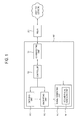
- FIG. 1 is a block diagram illustrating a configuration of an electronic device 100 according to an exemplary embodiment.
- the electronic device 100 includes a communicating unit 110, an encoding unit 120, an encrypting unit 130, a signal generating unit 140, a second signal generating unit 141 and a controller 150.
- the electronic device 100 enables wireless networking through a wireless network. Examples thereof may include a displaying apparatus, a personal video recorder (PVR), a digital versatile disc (DVD) player and/or a blue ray disc (BD) player, an audio component, a mobile phone, a personal computer (PC), a video console, a set top box, a recording and/or reproducing apparatus, and so on.
- examples of the electronic device 100 may also include a variety of electric home appliances capable of performing a wireless home network communication, such as a refrigerator, an air-conditioner, an electric rice cooker, a microwave oven, a video phone, an Internet phone, a heater, a washer and/or drier, a convection or conventional oven, a stove, and so on.
- the communicating unit 110 accesses a wireless network to thereby perform a wireless communication.
- the communicating unit 110 may join the wireless network through a relay 200 relaying communication in the wireless network, thereby performing wireless communication.
- the communicating unit 110 can perform any type of wireless network communication, including a wireless local area network (WLAN) communication.
- WLAN wireless local area network
- the communicating unit 110 may include any type of protocol available for wireless network communication, such as a WLAN communication protocol or a Wi-Fi communication protocol.
- the encoding unit 120 encodes a signal transmitted from or received by the communicating unit 110.
- the encoding unit 120 also encodes unique identification information of the electronic device, for example as a binary code.
- the unique identification information of the electronic device may be numerals, characters or a combination of numerals and characters. Accordingly, the encoding unit 120 encodes the unique identification information of the electronic device 100 including numerals and/or characters as a binary code.
- the unique identification information of the electronic device is information previously set to allow the relay 200 to identify the electronic device 100.
- the encoding unit 120 encodes the identification information based on a coding method selected from among a plurality of coding methods.
- the encoding unit 120 may employ a plurality of coding methods with respect to numerals/characters, and may encode the unique identification information (for example, binary-coded unique identification information) using at least one coding method selected from among the plurality of coding methods.
- unique identification information formed of four numerals and/or characters by applying different coding methods to each numeral and/or each character.
- the encoding unit 120 may repeat selection of a coding method from the plurality of coding methods on a predetermined cycle. For example, by repeating selection of the coding method on a predetermined cycle, network hacking from the outside may be prevented.
- the encoding unit 120 may further include a decoding unit (not shown) to decode the encoded signal received by the communicating unit 110.
- the electronic device 100 may further include an encrypting unit 130 which performs encryption.
- the encrypting unit 130 encrypts the identification information encoded by the encoding unit 120.
- the encrypting unit 130 may apply an encrypted algorithm such as an advanced encryption standard (AES) or a data encryption standard (DES), to encrypt the encoded identification information.
- AES advanced encryption standard
- DES data encryption standard
- the encrypting unit 130 may further include a decrypting unit (not shown) to decrypt the encrypted signal received by the communicating unit 110.
- the electronic device 100 may further include a signal generating unit 140 which generates a signal having a received signal strength identification (RSSI).
- RSSI received signal strength identification
- the generated signal with the RSSI pattern may be transmitted through the communicating unit 110.
- the signal generating unit 140 may generate the unique identification information of the electronic device 100, encoded by the encoding unit 120, as a signal having the RSSI pattern. It may also generate the unique identification information of the electronic device 100, encoded by the encoding unit 120 and encrypted by the encrypting unit 130, as a signal having the RSSI pattern.
- the RSSI identifies the strength of a received signal, and a numerical value of the RSSI varies depending upon wireless technologies. However, a range of the numeral values may be differently set according to the manufacturers of the electronic devices.
- the signal generating unit 140 generates a signal having the RSSI pattern as a signal having a cycle in microseconds.
- the signal generating unit 140 may generate a beacon signal having a RSSI pattern, and the beacon signal may have a cycle in microseconds. This will be described later in more detail with respect to FIGs. 2 and 3 .
- the electronic device 100 may further include a second signal generating unit 141 to generate an association request signal with regard to the relay 200.
- the second signal generating unit 141 may generate the association request signal for requesting a join to the wireless network relayed by the relay 200 after the relay 200 is identified for accessing the wireless network and an integrity of a relay signal received from the relay 200 is ascertained.
- the association request signal may include the identification information encrypted by the encrypting unit 130 for joining the wireless network.
- the identification information for joining the wireless network may include a personal identification number (PIN) for allowing the electronic device 100 to join the wireless network.
- PIN personal identification number
- the association request signal may include integrity information about the encrypted identification information.
- the relay 200 that receives the association request signal ascertains the identification information used in joining the wireless network and the integrity information, and transmits an association response signal to the electronic device 100 in response to the association request signal if the identification information is valid and has sufficient integrity.
- controller 150 controls the communicating unit 110 to initiate an access to the wireless network through the relay 200 when receiving the association response signal from the relay 200.
- the controller 150 confirms whether the electronic device 100 is powered on. If it is confirmed that the electronic device 100 is powered on, the controller 150 may control the communication unit 110 to receive a relay signal from the relay 200 and initiate the access to the wireless network.
- the relay signal may include a beacon signal periodically transmitted from the relay 200.
- the relay signal may include a probe response signal corresponding to a probe request signal requested by the communication unit 110.
- the relay signal may include a data frame that includes recognition information for initiating the access to the wireless network by the electronic device.
- the recognition information may include at least one of information about presence of the recognition information, information about a vendor of the electronic device, product information about the electronic device, and integrity information of the recognition information.
- the relay signal may include a signal having the RSSI pattern.
- the controller 150 determines whether an RSSI strength of the relay signal received from the relay 200 through the communicating unit 110 is equal to or higher than a predetermined threshold value.
- the electronic device 100 may receive a plurality of relay signals from a plurality of relays 200 through the communicating unit 110.
- the controller 150 determines whether each RSSI strength of the plurality of received relay signals is equal to or higher than each predetermined threshold value.
- a user may determine which relay 200 to use for communication.
- the controller 150 controls the encoding unit 120 and the encrypting unit 130 to encode and/or encrypt the unique identification information of the electronic device 100.
- the encoded and/or encrypted identification information is generated as a signal having a predetermined RSSI pattern by the signal generating unit 140, and transmitted to the relay 200 through the communicating unit 110.
- the controller 150 controls the encoding unit 120 and/or the encrypting unit 130 to decode and/or decrypt the signal received from the relay 200, thereby ascertaining the integrity of the signal. Accordingly, if it is determined that the signal has sufficient integrity, the controller 150 controls the second signal generating unit 141 to generate the association request signal and transmit the generated association request signal to the relay 200 through the communicating unit 100.
- the controller 150 controls the communicating unit 110 to initiate the access to the wireless network through the relay 200.
- the controller 150 may ascertain the recognition information for initiating the access to the wireless network by the electronic device, included in the data of the relay signal. As a result of ascertaining the recognition information, if the recognition information is valid and the relay signal has the sufficient integrity, the controller 150 controls the second signal generating unit 141 to generate the association request signal and transmit the generated association request signal to the relay 200 through the communicating unit 100.
- the association request signal may include the encrypted identification information and integrity information used to initiate the access to the wireless network. If the relay 200 transmits the association response signal corresponding to the association request signal through the communicating unit 110 after ascertaining the encrypted identification information and integrity information, the controller 150 controls the communicating unit 110 to initiate the access to the wireless network through the relay 200.
- the electronic device 100 may further include a user input unit (not shown).
- the user input unit is designed to input a power on/off signal, and may be provided as a button type and/or as a touch panel for a touch screen in the electronic device 100.
- the user input unit may be provided in various other or additional forms such as a remote controller, a keyboard, etc. connected to the electronic device 100 by wire or wirelessly.
- the controller can confirm the power on of the electronic device 100 if the electronic device 100 is powered on according to input of the power on signal through the user input unit.
- the electronic device 100 may include a plug and play (PnP) function.
- PnP plug and play
- the controller 150 can confirm the power on of the electronic device 100. If the PnP function is performed through a channel selection input, not a power on/off input by the user input unit, and the electronic device 100 is powered on, the controller 150 can confirm the power on of the electronic device 100.
- FIGs. 2A and 2B illustrate signal cycles according to an exemplary embodiment.
- FIG. 2A shows a cycle of a related art beacon signal.
- the related art beacon signal has a cycle in 100 to 200 milliseconds.
- FIG. 2B shows a cycle of a signal having an RSSI pattern generated by the signal generating unit 140.
- the cycle is in the unit of microseconds.
- FIG. 3 illustrates an example of generating a signal having an RSSI pattern of unique identification information of an electronic device 100 according to an exemplary embodiment.
- the RSSI pattern may be set to 10 (Low) to 127 (High), though it is understood that another exemplary embodiment is not limited thereto.
- the unique identification information of the electronic device 100 may include a mixture of characters and numerals, which may be binary-coded by the encoding unit 120 (i.e., 0 and 1).
- the unique identification information binary-coded by the encoding unit 120 may be generated in the signal generating unit 140 as a signal having an RSSI pattern, in which "0" indicates a signal having an RSSI strength of 10 (Low) and "1" indicates a signal having an RSSI strength of 127 (High).
- unique identification information of the electronic device 100 is "samsung0123," for the sake of convenience.
- a signal which is binary-coded into 8 bits (11010111) and generated having an RSSI strength 127 for "1" of the binary code and 10 for "0" of the binary code may be transmitted through the communicating unit 110.
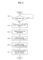
- FIG. 4 is a flow chart illustrating a network access of an electronic device 100 according to a first exemplary embodiment.
- the controller 150 of the electronic device 100 confirms whether the electronic device 100 is powered on (S100).
- a power on signal may be input through the user input unit (not shown), or may be input through a connection by a USB using a PnP function.
- the controller 150 controls the communicating unit 110 to receive a relay signal from the relay 200 (S110).
- the relay signal has an RSSI pattern. Accordingly, the controller 150 determines whether an RSSI strength of the relay signal is equal to or higher than a predetermined threshold value, and selects the relay 200 transmitting the relay signal, which has the RSSI strength equal to or higher than the predetermined threshold value as a result of the determination, as a candidate relay for initiating the access to the wireless network.
- the controller 150 controls the encoding unit 120 to encode unique identification information of the electronic device 100 (S120).
- the encoding unit 120 may binary-code the unique identification information, or may encode the unique identification information using at least one coding method selected from among a plurality of coding methods. Alternatively, the unique identification information may be changed according to a predetermined cycle for selection of a coding method from among the plurality of coding methods.
- the controller 150 may control the encrypting unit 130 to encrypt the encoded identification information according to an encryption algorithm (S130).
- the controller 150 may control the signal generating unit 140 to generate the encoded and encrypted identification information as a signal having a specific RSSI pattern (S140).
- the signal having the specific RSSI pattern has a cycle in microseconds, regardless of the size of the unique identification information.
- the controller 150 may control the communicating unit 110 to transmit the signal generated by the signal generating unit 140 and having the specific RSSI pattern to the relay 200 selected as the candidate relay.
- the controller 150 receives a response signal corresponding to the signal from the relay 200, and selects the relay 200 for initiating the access to the wireless network if it is determined that the response signal has sufficient integrity, thereby transmitting the association request signal to the relay 200.
- the controller 150 controls the communicating unit 110 to initiate the access to the wireless network (S150).
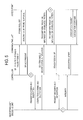
- FIG. 5 illustrates initiation of an access to a wireless network in an electronic device 100 according to a first exemplary embodiment in more detail.
- Wi-Fi protect setup A case where the electronic device 100 performs a wireless network communication using Wi-Fi will be described.
- Wi-Fi protect setup To perform the wireless network communication using Wi-Fi, an easier network join may be performed through Wi-Fi protect setup.
- a user In a related art electronic device, a user must press a Wi-Fi protect setup (WPS) button provided in the electronic device and a Wi-Fi access point, in order to initiate an easier access to the wireless network communication.
- WPS Wi-Fi protect setup
- the electronic device 100 enabling wireless networking through a wireless network, is configured to automatically initiate an access to the wireless network if the electronic device 100 is powered on, without any manipulation by the user.
- the controller 150 of the electronic device 100 actively controls the communicating unit 110 to transmit a probe request signal, so as to probe a Wi-Fi access point.
- the communicating unit 110 may receive a probe response signal from a neighboring Wi-Fi access point.
- a manual probe may be conducted by receiving a beacon signal periodically transmitted from the Wi-Fi access point.
- the controller 150 determines whether the RSSI strength of the probe response signal or the beacon signal received by the communicating unit 110 is greater than a preset specific threshold value. Where it is determined that there is no RSSI greater than the specific threshold value, or there is two or more RSSI greater than the specific threshold value, the user can determine to which access point an access is to be made.
- the controller 150 controls the encoding unit 120 and the encrypting unit 130 to respectively encode and encrypt the unique identification information of the electronic device 100.
- the encoded and encrypted identification information becomes a signal having a specific RSSI pattern by the signal generating unit 140, which is transmitted to the access point through the communicating unit 110.
- the access point having received the encoded and encrypted unique identification information of the electronic device 100, having the specific RSSI pattern, confirms the strength of the RSSI. If the identification information is recognized as being valid, the access point decodes and decrypts the encoded and encrypted identification information, thereby certifying the validity of the unique identification information. The access point also transmits the encoded and encrypted identification information thereof, having the specific RSSI pattern, to the communicating unit 110 of the electronic device 100.
- the controller 150 of the electronic device 100 decodes and decrypts the encoded and encrypted unique identification information of the access point, having the specific RSSI pattern of the access point, at the encoding unit 120 and the encrypting unit 130, respectively, thereby determining the integrity thereof. If the integrity is determined to be sufficient, the controller 150 controls the communicating unit 110 to transmit an association request to the access point. If an association response to the association request is received, the controller 150 controls the communicating unit 110 to initiate the access to the wireless network through the relay 200.
- the controller 150 may control the communicating unit 110 to allow the relay 200 to perform a course of EAPOL-Start, EAPOL-Request/Response (M1-M8), EAP_Request (Done) and EAP-Response (ACK), thereby joining the wireless network through the relay 200.
- an electronic device 100 automatically initiates an access to a wireless network if the electronic device 100 is powered on, without manipulation by the user, thereby increasing the user's convenience.
- FIG. 6 is a flow chart illustrating a network access of an electronic device 100 according to a second exemplary embodiment.
- the controller 150 of the electronic device 100 ascertains whether the electronic device 100 is powered on (S200).
- the controller 150 controls the communicating unit 110 to receive a relay signal from the relay 200 (S210).
- the relay signal includes a beacon signal periodically transmitted by the relay or a probe response signal corresponding to a probe request signal of the communicating unit 110.
- the relay signal is a signal having an RSSI pattern.
- the controller 150 determines whether an RSSI strength of the received relay signal is equal to or higher than a predetermined threshold value, and selects the relay 200 for initiating the access to the wireless network accordingly (S220). If a plurality of relay signals is received from the communicating unit 110, the selection of the candidate relay is the same as described in FIG. 4 , and thus repetitive descriptions thereof will be omitted herein.
- the controller 150 ascertains the recognition information included in the relay signal received through the communicating unit 110 and determines whether the relay signal has sufficient integrity (S230).
- the controller 150 controls the second signal generating unit 141 to generate the association request signal with the identification information used in joining the wireless network, and to transmit the generated association request signal to the relay 200 through the communicating unit 110 (S240).
- the controller 150 controls the communication unit 110 to initiate the access to the wireless network through the relay 200 (S250).
- the controller 150 may control the communicating unit 110 to allow the relay to perform a course of EAPOL-Start, EAPOL-Request/Response (M1-M8), EAP_Request (Done) and EAP-Response (ACK), thereby joining the wireless network through the relay 200.
- FIG. 7 illustrates that the electronic device 100 automatically joins the wireless network by communication with the relay 200, without any user's operation, such as a personal identification number (PIN) input, a push button input, or the like, through wireless protected setup (WPS) between the relay 200 for relaying communication in the wireless network based on the institute of electrical and electronics engineers (IEEE) 802.11 and the electronic device 100 to join the wireless network.
- PIN personal identification number
- WPS wireless protected setup
- a data frame transmitted and received between the electronic device and the relay is configured to depend on a chipset vendor according to vendors. Accordingly, there has been a problem that the electronic device and the relay are not compatible with each other and thus the WPS is not automatically performed.
- the electronic device 100 can automatically perform the WPS without a user's specific operation by ascertaining the communication of the data frame between the electronic device and the relay in an in-band of the WLAN and an integrity of the communication.
- the communication unit 110 receives a relay signal from the relay device 200 under the control of the controller 150.
- the relay signal may include a beacon signal periodically transmitted from the relay 200 or a probe response signal from the relay 200 corresponding to a probe request signal of the communicating unit 110.
- the relay signal is a signal having an RSSI pattern.
- the controller 150 determines whether an RSSI strength of the relay signal received through the communicating unit 110 is equal to or higher than a predetermined threshold value.
- the controller 150 ascertains the recognition information for initiating the access to the wireless network included in the data frame of the relay signal.
- the recognition information may include at least one of information about presence of the recognition information, information about a vendor of the electronic device, product information about the electronic device, and the integrity information of the recognition information.
- a data frame structure showing information about the presence of the recognition information may be as shown in FIG. 8 .
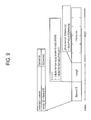
- FIG. 8 shows a frame structure of a capability information field in the data frame of the relay signal according to an exemplary embodiment.
- FIG. 8 shows a frame structure of a related art capability information field
- (B) shows a frame structure of a capability information field included in the relay signal received in the electronic device 100 according to the present exemplary embodiment.
- B5 designated as "SPAC” includes data that can be used to ascertain the presence of the recognition information for initiating the access to the wireless network.
- the "SPAC” may be designated as 0 or 1.
- the “SPAC” is designated as 0 if there exists no recognition information.
- the "SPAC” is designated as 1 if there exists the recognition information.
- the controller 150 ascertains whether the "SPAC" of the B5 of the frame structure of the capability information field is designated as 0 or 1.
- the controller 150 Ascertains whether or not the relay signal includes the information about the vendor of the electronic device 100 and/or the product information of the electronic device 100.
- FIG. 9 shows a data frame structure with regard to the information about a vendor of the electronic device and product information about the electronic device included in the relay signal according to an exemplary embodiment.
- Element ID indicates what information is included
- Length indicates the length of data
- Information includes information of 24 bits about the vendor of the electronic device 100 (Vendor ID) and product information of 8 bits (Product ID).
- the fields of "Element ID,” “Length,” and “Information” shown in FIG. 9 are merely exemplary, and it is understood that another exemplary embodiment is not limited thereto.
- the controller 150 ascertains whether the relay signal includes data such as the information about the vendor of the electronic device 100 and the product information, and ascertains the information about the vendor and the product information if the relay signal includes the information.
- the controller 150 determines whether the relay signal has sufficient integrity through the integrity information.
- FIG. 10 shows a data frame structure regarding the integrity of the relay signal according to an exemplary embodiment.
- Element ID indicates what information is included
- Length indicates the length of data
- Information includes information of 16 bits about the integrity (MIC).
- the sections of “Element ID,” “Length” and “Information” shown in FIG. 10 are merely exemplary, and it is understood that another exemplary embodiment is not limited thereto.
- the controller 150 determines whether the relay signal has sufficient integrity through the integrity information included in the relay signal, and progresses to the following steps if it is determined that relay signal has the sufficient integrity.
- FIG. 11 shows an exemplary embodiment of a data frame structure of the relay signal received from the relay 200 according to an exemplary embodiment.
- the relay signal may include the beacon signal periodically transmitted by the relay 200, or the probe response signal corresponding to the probe request signal of the communicating unit 110.
- the relay signal includes a frame body section following a MAC header.
- a capability information field includes information (SPAC) about presence of recognition information for initiating the access to the wireless network.
- the frame body further includes a data frame for information (VID) about the vendor of the electronic device 100, product information (PID), and integrity information (MIC). The data about the vendor information (VID), the product information (PID), and the integrity information (MIC) are not included in the frame body under the related art WPS network protocol.
- the controller 150 when receiving the relay signal, the controller 150 ascertains the SPAC of the capability information field and determines whether the SPAC is 1 or not. If the SPAC is 1, the controller 150 determines whether the vendor information (VID) of the electronic device 100 and the product information (PID) included in the frame body are correct.
- VID vendor information
- PID product information
- the controller 150 determines whether the relay signal has sufficient integrity through the integrity information (MIC).
- the controller 150 controls the second signal generating unit 141 to generate an association request signal with identification information used in joining the wireless network.
- FIGs. 12 and 13 shows data frame structures of the association request signal generated in the second signal generating unit 141 of the electronic device 100 according to a second exemplary embodiment.
- FIG. 12 shows a data structure of the identification information used in joining the wireless network.
- “Element ID” indicates what information is included
- “Length” indicates the length of data
- “Information” includes identification information (PIN) of 8 bits used in joining the wireless network.
- PIN identification information
- the identification information used in joining the wireless network may be encrypted by the encrypting unit 130 under control of the controller 150.
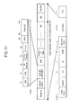
- FIG. 13 shows a data frame structure of the association request signal generated in the second signal generating unit 141.
- the association request signal includes a frame body section following a MAC header.
- a capability information field includes information (SPAC) about presence of recognition information for initiating the access to the wireless network.
- the frame body further includes a data frame for information (VID) about the vendor of the electronic device 100, product information (PID), integrity information (MIC), and identification information (PIN) used in joining the wireless network.
- the association request signal generated in the second signal generating unit 141 under the control of the controller 150 is transmitted to the relay 200 through the communicating unit 110.
- the relay 200 that receives the association request signal can ascertain the recognition information (e.g., the information about the presence of the recognition information, the vendor information of the electronic device, the product information, the integrity information, and the identification information used in joining the wireless network) included in the association request signal by the same or similar process of the controller 150 of the electronic device 100 in ascertaining the relay signal.
- the recognition information e.g., the information about the presence of the recognition information, the vendor information of the electronic device, the product information, the integrity information, and the identification information used in joining the wireless network
- the relay 200 transmits the association response signal corresponding to the association request signal to the electronic device 100.
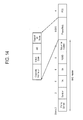
- FIG. 14 shows a data frame structure of the association response signal according to an exemplary embodiment.
- the association response signal includes status code data as a code for showing the status of the association request signal in the frame body section following the MAC header.
- the status code shows whether the association request signal is correct or not.
- the controller 150 When receiving the association response signal from the relay 200 through the communication unit 110 of the electronic device 100, the controller 150 ascertains the status code data included in the association response signal and controls the communicating unit 110 to allow the relay 200 to perform a course of EAPOL-Start, EAPOL-Request/Response (M1-M8), EAP_Request (Done) and EAP-Response (ACK) if all is correct, thereby joining the wireless network through the relay 200.
- the exemplary embodiments can also be embodied as computer-readable code on a computer-readable recording medium.
- the computer-readable recording medium is any data storage device that can store data that can be thereafter read by a computer system. Examples of the computer-readable recording medium include read-only memory (ROM), random-access memory (RAM), CD-ROMs, magnetic tapes, floppy disks, and optical data storage devices.
- the computer-readable recording medium can also be distributed over network-coupled computer systems so that the computer-readable code is stored and executed in a distributed fashion.
- the exemplary embodiments may be written as computer programs transmitted over a computer-readable transmission medium, such as a carrier wave, and received and implemented in general-use digital computers that execute the programs.
- one or more units of the electronic device 100 can include a processor or microprocessor executing a computer program stored in a computer-readable medium, such as a local storage.
- an automatic access to a wireless network can be initiated without any particular operation of a user such as a personal identification number (PIN) input, a button input or the like in order to join the wireless network once the electronic device is powered on, so that it is more convenient for the user to set the wireless network.
- PIN personal identification number
Landscapes
- Engineering & Computer Science (AREA)
- Computer Security & Cryptography (AREA)
- Computer Networks & Wireless Communication (AREA)
- Signal Processing (AREA)
- Mobile Radio Communication Systems (AREA)
Applications Claiming Priority (2)
| Application Number | Priority Date | Filing Date | Title |
|---|---|---|---|
| KR20090108756 | 2009-11-11 | ||
| KR1020100062844A KR20110052434A (ko) | 2009-11-11 | 2010-06-30 | 전자장치 및 그 네트워크 연결방법 |
Publications (1)
| Publication Number | Publication Date |
|---|---|
| EP2323447A2 true EP2323447A2 (fr) | 2011-05-18 |
Family
ID=43569667
Family Applications (1)
| Application Number | Title | Priority Date | Filing Date |
|---|---|---|---|
| EP10189858A Withdrawn EP2323447A2 (fr) | 2009-11-11 | 2010-11-03 | Dispositif électronique et son procédé d'évaluation du réseau |
Country Status (3)
| Country | Link |
|---|---|
| US (1) | US20110110521A1 (fr) |
| EP (1) | EP2323447A2 (fr) |
| JP (1) | JP2011103658A (fr) |
Cited By (1)
| Publication number | Priority date | Publication date | Assignee | Title |
|---|---|---|---|---|
| EP2701451A1 (fr) * | 2012-08-21 | 2014-02-26 | BSH Bosch und Siemens Hausgeräte GmbH | Module de communication pour un appareil ménager |
Families Citing this family (18)
| Publication number | Priority date | Publication date | Assignee | Title |
|---|---|---|---|---|
| JP5645748B2 (ja) | 2010-11-19 | 2014-12-24 | 京セラドキュメントソリューションズ株式会社 | 駆動機構及び画像形成装置 |
| EP2713671B1 (fr) * | 2011-05-27 | 2019-10-30 | Huawei Device Co., Ltd. | Procédé et appareil pour établissement de connexions pour répéteur wi-fi protégée |
| US8831568B2 (en) | 2011-09-27 | 2014-09-09 | Qualcomm Incorporated | Automatic configuration of a wireless device |
| IN2014MN01836A (fr) * | 2012-04-05 | 2015-07-03 | Qualcomm Inc | |
| US9031050B2 (en) | 2012-04-17 | 2015-05-12 | Qualcomm Incorporated | Using a mobile device to enable another device to connect to a wireless network |
| US9144096B2 (en) | 2012-09-07 | 2015-09-22 | Qualcomm Incorporated | Systems, apparatus, and methods for association in multi-hop networks |
| US9301276B2 (en) | 2012-09-07 | 2016-03-29 | Qualcomm Incorporated | Systems, apparatus, and methods for association in multi-hop networks |
| US9426837B2 (en) | 2012-09-07 | 2016-08-23 | Qualcomm Incorporated | Systems, apparatus and methods for association in multi-hop networks |
| KR20140052690A (ko) * | 2012-10-25 | 2014-05-07 | 삼성전자주식회사 | 전자장치 및 시스템의 제어방법 |
| US9301158B2 (en) | 2012-11-30 | 2016-03-29 | Qualcomm Incorporated | Systems and methods for optimization of branch synchronization node determination in a peer-to-peer network |
| US8806209B2 (en) * | 2012-12-22 | 2014-08-12 | Wigwag, Llc | Provisioning of electronic devices |
| CN104144473B (zh) * | 2013-05-09 | 2019-12-20 | 中兴通讯股份有限公司 | 一种选择可用接入网络的方法及用户设备 |
| CN104780589A (zh) * | 2014-01-13 | 2015-07-15 | 中兴通讯股份有限公司 | 一种实现Wifi访问网络的方法、系统及终端 |
| CN105430667B (zh) * | 2015-11-04 | 2019-07-09 | Tcl集团股份有限公司 | 一种增强wifi信号的方法、系统、及无线中继装置 |
| CN109643478B (zh) * | 2016-07-22 | 2019-12-27 | 亚马逊技术有限公司 | 用于无线音频/视频记录和通信装置的无线扬声器装置 |
| KR102414927B1 (ko) * | 2018-03-21 | 2022-06-30 | 삼성전자 주식회사 | 무선랜 서비스를 사용하는 기기의 인증 방법 및 장치 |
| KR102777451B1 (ko) * | 2020-03-23 | 2025-03-10 | 삼성전자주식회사 | 전자 장치 및 전자 장치의 제어 방법 |
| CA3113473A1 (fr) * | 2020-03-24 | 2021-09-24 | Arudi Srinivas Rajagopal | Dispositifs et methodes d`avertissement de trafic et d`enregistrement de donnees |
Family Cites Families (3)
| Publication number | Priority date | Publication date | Assignee | Title |
|---|---|---|---|---|
| US7366144B2 (en) * | 2002-03-25 | 2008-04-29 | Agere Systems Inc. | Method of dynamically setting at least one threshold at an access point in a wireless local area network and the access point |
| US7421075B2 (en) * | 2003-12-15 | 2008-09-02 | Microsoft Corporation | Wireless online cryptographic key generation method |
| US8000276B2 (en) * | 2007-02-05 | 2011-08-16 | Wefi, Inc. | Providing easy access to radio networks |
-
2010
- 2010-11-03 US US12/938,478 patent/US20110110521A1/en not_active Abandoned
- 2010-11-03 EP EP10189858A patent/EP2323447A2/fr not_active Withdrawn
- 2010-11-10 JP JP2010251995A patent/JP2011103658A/ja active Pending
Non-Patent Citations (1)
| Title |
|---|
| None |
Cited By (2)
| Publication number | Priority date | Publication date | Assignee | Title |
|---|---|---|---|---|
| EP2701451A1 (fr) * | 2012-08-21 | 2014-02-26 | BSH Bosch und Siemens Hausgeräte GmbH | Module de communication pour un appareil ménager |
| DE102012214792A1 (de) * | 2012-08-21 | 2014-02-27 | BSH Bosch und Siemens Hausgeräte GmbH | Kommunikationsmodul für ein Hausgerät |
Also Published As
| Publication number | Publication date |
|---|---|
| US20110110521A1 (en) | 2011-05-12 |
| JP2011103658A (ja) | 2011-05-26 |
Similar Documents
| Publication | Publication Date | Title |
|---|---|---|
| EP2323447A2 (fr) | Dispositif électronique et son procédé d'évaluation du réseau | |
| KR101462361B1 (ko) | 프로브를 이용한 2개의 장치 간의 보안 무선 링크 | |
| KR101799311B1 (ko) | 무선통신장치 및 그 제어방법 | |
| EP3777278B1 (fr) | Connexion automatique à un réseau sécurisé | |
| EP3016438B1 (fr) | Appareil de terminal utilisateur, appareil électronique, système et procédé de commande pour etablissement assisté de connection | |
| WO2016004134A2 (fr) | Systèmes et techniques destinés à une configuration de dispositif sans fil | |
| US12149763B2 (en) | Methods, systems, and media for presenting media content items using multiple devices | |
| JP2005318527A (ja) | 無線伝送装置、相互認証方法および相互認証プログラム | |
| KR102109051B1 (ko) | 기능 확장장치, 디스플레이 장치 및 이의 제어 방법 | |
| KR102248755B1 (ko) | 네트워크 시스템, 액세스 포인트 및 그의 연결 방법 | |
| JP7277210B2 (ja) | ネットワークシステム、通信端末、およびプログラム | |
| KR20130043336A (ko) | 디스플레이기기 및 디스플레이기기의 액세스 포인트 접속 방법 | |
| JP4489601B2 (ja) | セキュリティ情報の交換方法およびレコーダ装置ならびにテレビ受像機 | |
| KR20220052115A (ko) | 디스플레이 장치, 전자 장치 및 그 동작 방법 | |
| KR20110052434A (ko) | 전자장치 및 그 네트워크 연결방법 | |
| KR20090058362A (ko) | 홈네트워크에서 이동성을 보장하기 위한 시스템 및 방법 | |
| KR100665329B1 (ko) | 무선랜 av 송수신기간 자동 페어링 방법 | |
| JP7267505B2 (ja) | 機器、ネットワーク機器及びコマンド実行方法 | |
| JP2006279702A (ja) | ネットワークシステムに電子装置を配置する方法およびネットワークシステム | |
| WO2018109850A1 (fr) | Appareil de communication, appareil électrique, terminal, procédé de communication et programme |
Legal Events
| Date | Code | Title | Description |
|---|---|---|---|
| PUAI | Public reference made under article 153(3) epc to a published international application that has entered the european phase |
Free format text: ORIGINAL CODE: 0009012 |
|
| AK | Designated contracting states |
Kind code of ref document: A2 Designated state(s): AL AT BE BG CH CY CZ DE DK EE ES FI FR GB GR HR HU IE IS IT LI LT LU LV MC MK MT NL NO PL PT RO RS SE SI SK SM TR |
|
| AX | Request for extension of the european patent |
Extension state: BA ME |
|
| RAP1 | Party data changed (applicant data changed or rights of an application transferred) |
Owner name: SAMSUNG ELECTRONICS CO., LTD. |
|
| STAA | Information on the status of an ep patent application or granted ep patent |
Free format text: STATUS: THE APPLICATION HAS BEEN WITHDRAWN |
|
| 18W | Application withdrawn |
Effective date: 20130422 |