EP2323574B1 - Ensemble espaceur d'apophyses épineuses - Google Patents
Ensemble espaceur d'apophyses épineuses Download PDFInfo
- Publication number
- EP2323574B1 EP2323574B1 EP09791491A EP09791491A EP2323574B1 EP 2323574 B1 EP2323574 B1 EP 2323574B1 EP 09791491 A EP09791491 A EP 09791491A EP 09791491 A EP09791491 A EP 09791491A EP 2323574 B1 EP2323574 B1 EP 2323574B1
- Authority
- EP
- European Patent Office
- Prior art keywords
- caudal
- cranial
- interspinous
- interspinous spacer
- paddle
- Prior art date
- Legal status (The legal status is an assumption and is not a legal conclusion. Google has not performed a legal analysis and makes no representation as to the accuracy of the status listed.)
- Active
Links
Images



Classifications
-
- A—HUMAN NECESSITIES
- A61—MEDICAL OR VETERINARY SCIENCE; HYGIENE
- A61B—DIAGNOSIS; SURGERY; IDENTIFICATION
- A61B17/00—Surgical instruments, devices or methods
- A61B17/56—Surgical instruments or methods for treatment of bones or joints; Devices specially adapted therefor
- A61B17/58—Surgical instruments or methods for treatment of bones or joints; Devices specially adapted therefor for osteosynthesis, e.g. bone plates, screws or setting implements
- A61B17/68—Internal fixation devices, including fasteners and spinal fixators, even if a part thereof projects from the skin
- A61B17/70—Spinal positioners or stabilisers, e.g. stabilisers comprising fluid filler in an implant
- A61B17/7062—Devices acting on, attached to, or simulating the effect of, vertebral processes, vertebral facets or ribs ; Tools for such devices
- A61B17/7067—Devices bearing against one or more spinous processes and also attached to another part of the spine; Tools therefor
-
- A—HUMAN NECESSITIES
- A61—MEDICAL OR VETERINARY SCIENCE; HYGIENE
- A61B—DIAGNOSIS; SURGERY; IDENTIFICATION
- A61B17/00—Surgical instruments, devices or methods
- A61B17/56—Surgical instruments or methods for treatment of bones or joints; Devices specially adapted therefor
- A61B17/58—Surgical instruments or methods for treatment of bones or joints; Devices specially adapted therefor for osteosynthesis, e.g. bone plates, screws or setting implements
- A61B17/68—Internal fixation devices, including fasteners and spinal fixators, even if a part thereof projects from the skin
- A61B17/70—Spinal positioners or stabilisers, e.g. stabilisers comprising fluid filler in an implant
-
- A—HUMAN NECESSITIES
- A61—MEDICAL OR VETERINARY SCIENCE; HYGIENE
- A61B—DIAGNOSIS; SURGERY; IDENTIFICATION
- A61B17/00—Surgical instruments, devices or methods
- A61B17/56—Surgical instruments or methods for treatment of bones or joints; Devices specially adapted therefor
- A61B17/58—Surgical instruments or methods for treatment of bones or joints; Devices specially adapted therefor for osteosynthesis, e.g. bone plates, screws or setting implements
- A61B17/68—Internal fixation devices, including fasteners and spinal fixators, even if a part thereof projects from the skin
- A61B17/70—Spinal positioners or stabilisers, e.g. stabilisers comprising fluid filler in an implant
- A61B17/7047—Clamps comprising opposed elements which grasp one vertebra between them
-
- A—HUMAN NECESSITIES
- A61—MEDICAL OR VETERINARY SCIENCE; HYGIENE
- A61B—DIAGNOSIS; SURGERY; IDENTIFICATION
- A61B17/00—Surgical instruments, devices or methods
- A61B17/56—Surgical instruments or methods for treatment of bones or joints; Devices specially adapted therefor
- A61B17/58—Surgical instruments or methods for treatment of bones or joints; Devices specially adapted therefor for osteosynthesis, e.g. bone plates, screws or setting implements
- A61B17/68—Internal fixation devices, including fasteners and spinal fixators, even if a part thereof projects from the skin
- A61B17/70—Spinal positioners or stabilisers, e.g. stabilisers comprising fluid filler in an implant
- A61B17/7053—Spinal positioners or stabilisers, e.g. stabilisers comprising fluid filler in an implant with parts attached to bones or to each other by flexible wires, straps, sutures or cables
-
- A—HUMAN NECESSITIES
- A61—MEDICAL OR VETERINARY SCIENCE; HYGIENE
- A61B—DIAGNOSIS; SURGERY; IDENTIFICATION
- A61B17/00—Surgical instruments, devices or methods
- A61B17/56—Surgical instruments or methods for treatment of bones or joints; Devices specially adapted therefor
- A61B17/58—Surgical instruments or methods for treatment of bones or joints; Devices specially adapted therefor for osteosynthesis, e.g. bone plates, screws or setting implements
- A61B17/68—Internal fixation devices, including fasteners and spinal fixators, even if a part thereof projects from the skin
- A61B17/70—Spinal positioners or stabilisers, e.g. stabilisers comprising fluid filler in an implant
- A61B17/7056—Hooks with specially-designed bone-contacting part
-
- A—HUMAN NECESSITIES
- A61—MEDICAL OR VETERINARY SCIENCE; HYGIENE
- A61B—DIAGNOSIS; SURGERY; IDENTIFICATION
- A61B17/00—Surgical instruments, devices or methods
- A61B17/56—Surgical instruments or methods for treatment of bones or joints; Devices specially adapted therefor
- A61B17/58—Surgical instruments or methods for treatment of bones or joints; Devices specially adapted therefor for osteosynthesis, e.g. bone plates, screws or setting implements
- A61B17/68—Internal fixation devices, including fasteners and spinal fixators, even if a part thereof projects from the skin
- A61B17/70—Spinal positioners or stabilisers, e.g. stabilisers comprising fluid filler in an implant
- A61B17/7062—Devices acting on, attached to, or simulating the effect of, vertebral processes, vertebral facets or ribs ; Tools for such devices
- A61B17/7065—Devices with changeable shape, e.g. collapsible or having retractable arms to aid implantation; Tools therefor
-
- A—HUMAN NECESSITIES
- A61—MEDICAL OR VETERINARY SCIENCE; HYGIENE
- A61B—DIAGNOSIS; SURGERY; IDENTIFICATION
- A61B17/00—Surgical instruments, devices or methods
- A61B17/56—Surgical instruments or methods for treatment of bones or joints; Devices specially adapted therefor
- A61B17/58—Surgical instruments or methods for treatment of bones or joints; Devices specially adapted therefor for osteosynthesis, e.g. bone plates, screws or setting implements
- A61B17/68—Internal fixation devices, including fasteners and spinal fixators, even if a part thereof projects from the skin
- A61B17/70—Spinal positioners or stabilisers, e.g. stabilisers comprising fluid filler in an implant
- A61B17/7062—Devices acting on, attached to, or simulating the effect of, vertebral processes, vertebral facets or ribs ; Tools for such devices
- A61B17/7068—Devices comprising separate rigid parts, assembled in situ, to bear on each side of spinous processes; Tools therefor
-
- A—HUMAN NECESSITIES
- A61—MEDICAL OR VETERINARY SCIENCE; HYGIENE
- A61B—DIAGNOSIS; SURGERY; IDENTIFICATION
- A61B17/00—Surgical instruments, devices or methods
- A61B17/56—Surgical instruments or methods for treatment of bones or joints; Devices specially adapted therefor
- A61B17/58—Surgical instruments or methods for treatment of bones or joints; Devices specially adapted therefor for osteosynthesis, e.g. bone plates, screws or setting implements
- A61B17/68—Internal fixation devices, including fasteners and spinal fixators, even if a part thereof projects from the skin
- A61B17/84—Fasteners therefor or fasteners being internal fixation devices
- A61B17/86—Pins or screws or threaded wires; nuts therefor
-
- A—HUMAN NECESSITIES
- A61—MEDICAL OR VETERINARY SCIENCE; HYGIENE
- A61B—DIAGNOSIS; SURGERY; IDENTIFICATION
- A61B17/00—Surgical instruments, devices or methods
- A61B17/56—Surgical instruments or methods for treatment of bones or joints; Devices specially adapted therefor
- A61B17/58—Surgical instruments or methods for treatment of bones or joints; Devices specially adapted therefor for osteosynthesis, e.g. bone plates, screws or setting implements
- A61B17/68—Internal fixation devices, including fasteners and spinal fixators, even if a part thereof projects from the skin
- A61B17/84—Fasteners therefor or fasteners being internal fixation devices
- A61B17/86—Pins or screws or threaded wires; nuts therefor
- A61B17/8665—Nuts
-
- A—HUMAN NECESSITIES
- A61—MEDICAL OR VETERINARY SCIENCE; HYGIENE
- A61B—DIAGNOSIS; SURGERY; IDENTIFICATION
- A61B17/00—Surgical instruments, devices or methods
- A61B17/56—Surgical instruments or methods for treatment of bones or joints; Devices specially adapted therefor
- A61B17/58—Surgical instruments or methods for treatment of bones or joints; Devices specially adapted therefor for osteosynthesis, e.g. bone plates, screws or setting implements
- A61B17/88—Osteosynthesis instruments; Methods or means for implanting or extracting internal or external fixation devices
-
- A—HUMAN NECESSITIES
- A61—MEDICAL OR VETERINARY SCIENCE; HYGIENE
- A61F—FILTERS IMPLANTABLE INTO BLOOD VESSELS; PROSTHESES; DEVICES PROVIDING PATENCY TO, OR PREVENTING COLLAPSING OF, TUBULAR STRUCTURES OF THE BODY, e.g. STENTS; ORTHOPAEDIC, NURSING OR CONTRACEPTIVE DEVICES; FOMENTATION; TREATMENT OR PROTECTION OF EYES OR EARS; BANDAGES, DRESSINGS OR ABSORBENT PADS; FIRST-AID KITS
- A61F2/00—Filters implantable into blood vessels; Prostheses, i.e. artificial substitutes or replacements for parts of the body; Appliances for connecting them with the body; Devices providing patency to, or preventing collapsing of, tubular structures of the body, e.g. stents
- A61F2/02—Prostheses implantable into the body
- A61F2/30—Joints
- A61F2/44—Joints for the spine, e.g. vertebrae, spinal discs
-
- A—HUMAN NECESSITIES
- A61—MEDICAL OR VETERINARY SCIENCE; HYGIENE
- A61B—DIAGNOSIS; SURGERY; IDENTIFICATION
- A61B17/00—Surgical instruments, devices or methods
- A61B17/02—Surgical instruments, devices or methods for holding wounds open, e.g. retractors; Tractors
- A61B17/025—Joint distractors
-
- A—HUMAN NECESSITIES
- A61—MEDICAL OR VETERINARY SCIENCE; HYGIENE
- A61B—DIAGNOSIS; SURGERY; IDENTIFICATION
- A61B17/00—Surgical instruments, devices or methods
- A61B17/56—Surgical instruments or methods for treatment of bones or joints; Devices specially adapted therefor
- A61B17/58—Surgical instruments or methods for treatment of bones or joints; Devices specially adapted therefor for osteosynthesis, e.g. bone plates, screws or setting implements
- A61B17/68—Internal fixation devices, including fasteners and spinal fixators, even if a part thereof projects from the skin
- A61B17/70—Spinal positioners or stabilisers, e.g. stabilisers comprising fluid filler in an implant
- A61B17/7049—Connectors, not bearing on the vertebrae, for linking longitudinal elements together
- A61B17/7052—Connectors, not bearing on the vertebrae, for linking longitudinal elements together of variable angle or length
-
- A—HUMAN NECESSITIES
- A61—MEDICAL OR VETERINARY SCIENCE; HYGIENE
- A61B—DIAGNOSIS; SURGERY; IDENTIFICATION
- A61B17/00—Surgical instruments, devices or methods
- A61B17/56—Surgical instruments or methods for treatment of bones or joints; Devices specially adapted therefor
- A61B17/58—Surgical instruments or methods for treatment of bones or joints; Devices specially adapted therefor for osteosynthesis, e.g. bone plates, screws or setting implements
- A61B17/68—Internal fixation devices, including fasteners and spinal fixators, even if a part thereof projects from the skin
- A61B17/84—Fasteners therefor or fasteners being internal fixation devices
- A61B17/86—Pins or screws or threaded wires; nuts therefor
- A61B17/8605—Heads, i.e. proximal ends projecting from bone
-
- A—HUMAN NECESSITIES
- A61—MEDICAL OR VETERINARY SCIENCE; HYGIENE
- A61B—DIAGNOSIS; SURGERY; IDENTIFICATION
- A61B17/00—Surgical instruments, devices or methods
- A61B17/56—Surgical instruments or methods for treatment of bones or joints; Devices specially adapted therefor
- A61B17/58—Surgical instruments or methods for treatment of bones or joints; Devices specially adapted therefor for osteosynthesis, e.g. bone plates, screws or setting implements
- A61B17/68—Internal fixation devices, including fasteners and spinal fixators, even if a part thereof projects from the skin
- A61B17/84—Fasteners therefor or fasteners being internal fixation devices
- A61B17/86—Pins or screws or threaded wires; nuts therefor
- A61B17/8695—Washers
Definitions
- the present invention relates generally to orthopedics. More specifically, the present invention relates to an interspinous spacer assembly for stabilizing the human spine.
- a human vertebra has a rearwardly projecting portion known as a spinous process. Bending or the natural aging and degeneration of the spine can cause the spinous processes of adjacent vertebrae to be moved toward each other. This constricts the space in the spinal canal and foramina and, thus, may cause pain. Such constriction, known as stenosis, can be treated by the use of an implant in the space between adjacent spinous processes.
- spinal stenosis there are two types of spinal stenosis: (1) hard or rigid spinal stenosis, or (2) soft or dynamic spinal stenosis. In both cases, spinal stenosis may be caused by excessive growth of tissue due to degeneration, loss of disc height, as well as disorders such as spondilolisthesis where the normal relative position and/or orientation of the adjacent vertebrae have been modified.
- the present invention is directed to an interspinous spacer assembly for implantation and/or affixation between spinous processes of adjacent superior and inferior vertebrae.
- the interspinous spacer assembly preferably includes a spacer member sized and configured for insertion into the space between adjacent spinous processes and an engagement mechanism for operatively coupling the spacer member to the adjacent spinous processes and for preventing migration of the assembly once implanted.
- the interspinous spacer assembly is adjustable in height so that the user can conform the interspinous spacer assembly to the individual anatomy of a patient's spine.
- An interspinous spacer assembly with the features as defined in the preamble of claim 1 is known from WO 2006/084444 A2 .
- the present invention relates to an interspinous spacer assembly for insertion into an interspinous space between a spinous process of a superior vertebral body and a spinous process of an inferior vertebral body.
- the interspinous spacer assembly includes at least one interspinous spacer member sized and configured for insertion into the interspinous space.
- Each spacer member includes cranial paddle for contacting an inferior surface of the spinous process of the superior vertebral body and a caudal paddle for contacting a superior surface of the spinous process of the inferior vertebral body.
- the cranial paddle is moveable with respect to the caudal paddle so that an overall height of the spacer member is adjustable.
- the cranial and caudal paddles each include one of first and second lateral projections extending therefrom or first and second lateral bores formed therein.
- the interspinous spacer assembly also includes an engagement mechanism for operatively coupling the spacer member to the spinous processes of the superior and inferior vertebral bodies.
- the engagement mechanism includes a first member, a second member, a third member and a fourth member.
- Each of the first, second, third and fourth members include one of a bore for receiving one of the projections extending from the cranial and caudal paddles or a projection for engaging one of the bores formed in the cranial and caudal paddles.
- the interacting projections and bores enable the cranial and caudal paddles to rotate about an axis.
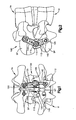
- Fig. 1 illustrates a posterior elevational view of an embodiment of an interspinous spacer assembly, not forming part of the present invention, mounted to superior and inferior vertebrae;
- Fig. 2 illustrates a side elevational view of the interspinous spacer assembly shown in Fig. 1 ;
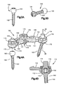
- Fig. 3A illustrates a side perspective view of an exemplary embodiment of a single headed bone screw that may be used in combination with the interspinous spacer assembly shown in Fig. 1 ;
- Fig. 3B illustrates a side perspective view of an exemplary embodiment of a double headed bone screw that may be used in combination with interspinous spacer assembly shown in Fig. 1 ;
- Fig. 4A is a partially exploded side perspective view of the interspinous spacer assembly show in Fig. 1 ;
- Fig. 4B is a cross-sectional view of the interspinous spacer assembly taken along line 4B-4B from Fig. 4A ;
- Fig. 5 illustrates a side perspective view of a first preferred embodiment of an interspinous spacer assembly according to the present invention
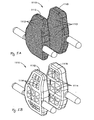
- Fig. 5A illustrates a partial, side perspective view of the interspinous spacer assembly illustrated in Fig. 5 with the interspinous spacer member having pores;
- Fig. 5B illustrates a partial, side perspective view of the interspinous spacer assembly illustrated in Fig. 5 with the interspinous spacer member having cavities
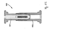
- Fig. 5C illustrates a cross-sectional view of an exemplary linear ratchet mechanism for coupling the interspinous spacer assemblies to the adjacent spinous processes
- Fig. 6 illustrates a partial, side perspective view of a second preferred embodiment of an interspinous spacer assembly according to the present invention, the interspinous spacer assembly including the interspinous spacer member shown in Fig. 5 with an adjustable engagement mechanism for adjustably coupling the spacer member to adjacent spinous processes, the adjustable engagement mechanism being configured as a multilevel construct;
- Fig. 7 illustrates a partial, side perspective view of an embodiment of an interspinous spacer assembly not forming part of the present invention.
- Fig. 8 illustrates a side perspective view of the interspinous spacer assembly shown in Fig.7 coupled to adjacent spinous processes.
- an interspinous spacer assembly for implantation and/or affixation between spinous processes SP of adjacent vertebrae, including a superior vertebra Vs and an inferior vertebra Vi to treat spinal stenosis or any condition wherein spacing between the spinous processes SP of the adjacent vertebrae Vs, Vi is desired.
- the interspinous spacer assembly includes an interspinous spacer member sized and configured for insertion into the space between adjacent spinous processes SP and an engagement mechanism for operatively coupling the spacer member to one or more of the adjacent spinous processes SP.
- the interspinous spacer assembly is adjustable so that the user can configure the interspinous spacer assembly to fit the anatomy of the patient's spine.
- the interspinous spacer assembly may be fully or partially adjustable.
- the height, width and/or angle of the spacer assembly may be adjustable.
- only the height, only the width or only the angle of the spacer member may be adjustable, or the spacer member may be non-adjustable.
- the height, width and/or the angle of the spacer member may be adjustable to only a certain extent or limit.
- the engagement mechanism is preferably adjustable so that the user can adjust the engagement mechanism such as, for example, the orientation, height, width, etc., as necessary to engage the patient's spinous processes SP.
- the adjustability of the engagement mechanism may be limited or non-adjustable.
- the method of implanting the interspinous spacer preferably allows a surgeon to adjust the interspinous spacer and/or the orientation of the interspinous spacer in the patient.
- the interspinous spacer assembly of the present invention may be implanted using a number of different approaches.
- the interspinous spacer assembly may be inserted laterally into the interspinous space or it may be implanted via a range of different posterior approaches, preferably without disruption, damage or removal of the spinal ligaments (e.g. ligaments remain intact), although, the ligaments may be disrupted, damaged, cut and/or removed to facilitate implantation of the interspinous spacer assembly or portions thereof.
- the interspinous spacer assembly of the present invention generally allows for a less invasive implantation procedure, different embodiments of the present invention may require varying degrees of invasiveness during implantation.
- the lateral approach of implanting the interspinous spacer assembly may be less invasive than posterior approaches.
- One less invasive implantation procedure may allow an interspinous spacer member of the interspinous spacer assembly of the present invention to be implanted between adjacent spinous processes SP and be coupled to adjacent spinous processes SP via an engagement mechanism fixed to adjacent spinous processes SP at the interface of the supra spinous ligament and the spinous processes SP, thus preserving the muscles attached to the spinous processes SP.
- the interspinous spacer assembly may be used to treat spinal stenosis in combination with decompression.
- the interspinous spacer assembly may be used to treat spinal stenosis without any additional treatment.
- the interspinous spacer assembly of the present invention may allow for application of distractive force as well as a compressive force to the same spinal level (e.g. distractive force in case of extension of the spine and compressive force in case of flexion of the spine).
- the interspinous spacer assembly includes an interspinous spacer member and an engagement mechanism for engaging one or more of the spinous processes SP.
- the engagement mechanism may include wings, plates, hooks, etc. that prevent migration of the interspinous spacer assembly.
- the engagement mechanism may be adjustable in length, bendable, polyaxial with respect to the spacer member, etc . to enable adaptability to the individual anatomy of a particular patient's spine and prevent migration of the interspinous spacer assembly once implanted into the patient.
- the engagement member may engage the patient's spinous processes SP in a variety of different ways including, for example, via one or more screws, bolts, rivets, spikes, or other protrusions and/or via compression.
- the engagement mechanism may be operatively coupled to the interspinous spacer member or members in a variety of different ways.
- One having ordinary skill in the art will recognize that the various engagement mechanisms described for the preferred embodiments of the interspinous spacer assemblies may be adapted and interchanged between the interspinous spacer assemblies of preferred embodiments, without significantly impacting the structure and operation of the implants.
- the interspinous spacer member of the interspinous spacer assembly is made from several parts, for example, two interspinous spacer paddles function as the spacer member, such that each paddle contacts one of the adjacent spinous processes SP.
- the spacer paddles are adjustable with respect to one another so that the height of the spacer member can be adjusted or the distance between the paddles can be modified.
- the interspinous spacer may be formed by parts that serve multiple functions.
- the interspinous spacer assembly and components thereof may be made from any biocompatible material including but not limited to metals such as, e.g., titanium, titanium alloys, stainless steel, etc., polymers such as, e.g., PEEK, PCU, etc ., and combinations thereof.
- metals such as, e.g., titanium, titanium alloys, stainless steel, etc.
- polymers such as, e.g., PEEK, PCU, etc ., and combinations thereof.
- PEEK polymers
- PCU polymers
- the interspinous spacer assembly may also promote spinal fusion for example, by constructing the spacer member from a mesh or porous type material or structure. Alternatively and/or in addition, perforations or cavities may be formed in the spacer member.
- the method of implanting the interspinous spacer assembly may also promote spinal fusion.
- a surgeon implanting the interspinous spacer assembly between adjacent spinous processes SP may also implant bone chips or other biocompatible implant material that fuses with the adjacent spinal processes through cavities or pores formed in the interspinous spacer assembly.
- an embodiment of an interspinous spacer assembly 100 which does not form part of the invention, includes an interspinous spacer member 110 sized and configured for insertion into an interspinous space between adjacent spinous processes SP and an engagement mechanism 105 for operatively coupling the spacer member 110 to the adjacent spinous process SP.
- the spacer member 110 may be designed as a non-adjustable, rigid body, although it is envisioned that an adjustable spacer member such as those described herein with respect to certain preferred embodiments may be used.
- the spacer member 110 preferably includes a caudal spacer portion 112 for contacting a superior surface of the inferior spinous process SP and a cranial spacer portion 115 for contacting an inferior surface of the superior spinous process SP.
- the bone contacting surfaces of the cranial and caudal spacer portions 115, 112 preferably include seats (e.g., concave or U-shaped recesses, See Fig. 1 ) for receiving the adjacent spinous processes SP.
- the spacer member 110 may be configured such that it is implanted at the posterior ends of the adjacent spinal processes SP or further toward the anterior of the adjacent spinal processes SP.
- the spacer member 110 may also include a projection 120 extending from one or both of the lateral sides thereof for engaging the engagement mechanism 105.
- the engagement mechanism 105 may be implanted on either one (unilateral construct) or both sides (bilateral construct) of the spacer member 110 and adjacent to the spinous processes SP.
- the spacer member 110 includes one or more curvate or spherical projections 120 for engaging a pop-on coupling mechanism 170 operatively associated with the engagement mechanism 105, as will be described in greater detail below, so that the engagement mechanism 105 may polyaxial rotate with respect to the spacer member 110.
- This configuration enables the user to adjust the position of the engagement mechanism 105 with respect to the spacer member 110.
- other types of coupling mechanisms may be used, for examples, interconnecting threads, screws, rivets, bolts, etc.
- the engagement mechanism 105 may be in the form of one or more plates 130, 140 for coupling the spacer member 110 to the adjacent spinous processes SP. As shown, the engagement mechanism 105 is preferably in the form of first and second plate assemblies 130, 140 for coupling the spacer member 110 to the adjacent upper and lower spinous processes SP.
- the plate assemblies 130, 140 preferably have adjustable lengths and can be adjusted to accommodate various fixation angles with respect to the spacer member 110.
- the adjustability of the lengths of the plates 130, 140 is preferably achieved through a telescopic construction of the plates 130, 140.
- each of the plate assemblies 130, 140 of the first preferred embodiment includes a female portion 131, 141 and a male portion 132, 142 whereby the male portion 132, 142 is slidably received within the female portion 131, 141 so that the overall length of the assemblies 130, 140 can be adjusted.
- the plates assemblies 130, 140 are preferably connected to the adjacent spinous processes SP and/or laminae via one or more bone fixation elements, more preferably bone screws 160.
- the bone screws 160 preferably include an enlarged, curvate or semi-spherical head portion 162 and an externally threaded shaft portion 163 for engaging the patient's spinal processes.
- the head portion 162 preferably includes a mechanism for engaging a screwdriver (not shown).
- the head portion 162 preferably includes a plurality of recesses for engaging a plurality of projections formed on a tip of a screwdriver, although other configurations are envisioned, including but not limited to, an internal recess, an external hexagon, a star drive pattern, a Phillips head pattern, a slot for a screw driver, a threading for a correspondingly threaded post, etc.
- the specific features of the shaft 163 including, for example, thread pitch, self drilling configurations, self tapping configurations, shaft diameter, shaft shape, etc. are interchangeable, and it would be apparent to one having ordinary skill in the art that the bone screws 160 are not limited to any particular type of shaft 163 or thread configuration.
- the bone screw 160 may also include a reduced diameter neck portion between the head portion 162 and the shaft portion 163, which accommodates the polyaxial connection of the bone screws 160 to the plate assemblies 130, 140.
- the bone screws 160 may further be cannulated and fenestrated (not shown) such that openings extend outwardly from a central hollow channel in a cannulated screw to urge fluid out of the screws 160 during injection or draw fluid into the central hollow channel from sides of the screw 160 during extraction of material adjacent the screws 160.
- the screws 160 may include a single head portion 162 as is generally known in the art.
- the screws 160 may include dual head portions. That is, a second head portion 164 may be attached to the threaded shaft portion 163 of a first bone screw 160 after the first screw 160 has been inserted into and through the spinous process SP.
- a bilateral construct wherein plates 130, 140 are placed on both lateral sides of the spinous processes SP, may be coupled to the same bone screw 160.
- single head screws may be inserted into the spinous processes SP on both sides of the spinous processes SP.
- the plate assemblies 130, 140 of the first preferred embodiment can be mounted to the curvate head portion 162 of the bone screws 160 and to the curvate projection 120 extending from the spacer member 110 by any coupling means or mechanism now or hereafter known in the art.
- the plate assemblies 130, 140 are mounted to the screws 160 and to the spacer member 110 by a pop-on mechanism 170 so that the plate assemblies 130, 140 can be coupled to the bone screws 160 and the spacer member 110 after the bone screws 160 and the spacer member 110 have been implanted, thus allowing visibility during screw insertion and simplifying the surgical technique.
- the pop-on mechanism 170 of the first preferred embodiment includes a flexible collet 172 having a semi-spherical recess 173 for receiving the curvate or semi-spherical head portion 162 of the bone screws 160 and the curvate projection 120 extending from the spacer member 110.
- the collet 172 includes a threaded second end 174 extending therefrom so that the threaded end 174 of the collet 172 may extend through a hole or slot formed in the plate assemblies 130, 140 before engaging a nut member 176.
- the user may rotate the nut member 176, which in turn causes the collet 172 to move with respect to the hole or slot formed in the plate assemblies 130, 140, thereby causing the collet 172 to compress against the curvate head portion 162 of the bone screw 160 and projection 120 to secure the relative position of the plate assemblies 130, 140 with respect to the spacer member 110 and the bone screws 160.
- the plates 130, 140 are installed on both sides of the interspinous spacer 110 and a second pop-on coupling mechanism 170 is provided to engage the spherical projection 120 extending from the spacer member 110 for coupling the spacer member 110 to the additional set of plates 130, 140 as well as coupling the plates 130, 140 to each other.
- one or more spinal rods can be used in place of the preferred plates 130, 140.
- the bone screws 160 may be secured in the spinous process SP or in the pedicles of the vertebrae Vs, Vi.
- the system may be used without a spacer member 110 implanted between the adjacent vertebrae Vs, Vi.
- a first preferred embodiment of the interspinous spacer assembly 1100 includes an interspinous spacer member 1110 having a cranial spacer paddle 1112 for contacting an inferior surface of the superior spinous process SP and a caudal spacer paddle 1115 for contacting a superior surface of the inferior spinous process.
- the cranial spacer paddle 1112 is moveable with respect to the caudal spacer paddle 1115 so that the overall height of interspinous spacer member 1110 can be adjusted.
- the engagement mechanism 1105 preferably includes first, second, third and fourth telescopic members or plates 1130, 1135, 1140, 1145, similar to previous embodiments described above.
- the interspinous spacer assembly 1100 of the first preferred embodiment is depicted with its ventral (or anterior) side up to illustrate that the width of the cranial spacer paddle 1112 and the caudal spacer paddle 1115 taper toward the ventral edge of the paddles 1112, 1115, wherein such tapered configuration aids implantation and may be used in any embodiment described herein.
- the bone contacting surface of the cranial spacer paddle 1112 may be curved for engaging the inferior surface of the superior spinous process SP while the bone contacting surface of the caudal paddle 1115 may be flat for adapting to the natural curvature of the spinal processes SP. Referring to Fig.
- the cranial spacer paddle 1112 and/or the caudal spacer paddle 1115 may include pores or perforations 1113.
- the pores or perforations 1113 may permit bone growth into the spacer paddles 1112, 1115.
- the cranial spacer paddle 1112 and/or the caudal spacer paddle 1115 may alternatively include cavities 1114.
- the cavities 1114 may permit bone growth and fusion through the spacer paddles 1112, 1115.
- the configurations of interspinous spacer member 1110 of the first preferred embodiment with pores or perforations 1113 or with cavities 1114 may be applied to all the embodiments of the present invention, although it is not shown in the illustrative figures for other embodiments.
- the cranial and caudal spacer paddles 1112, 111 preferably include projections 1120, more preferably cylindrical projections, extending therefrom for engaging the engagement mechanism 1105 so that the orientation ( e.g. , angle) of the cranial and caudal spacer paddles 1112, 1115 can be adjusted. That is, by coupling the cranial and caudal spacer paddles 1112, 1115 to the engagement mechanism 1105 via cylindrical projections 1120, the cranial and caudal spacer paddles 1112, 1115 are allowed to rotate about their axes to thereby allow better adaptation of the interspinous spacer member 1110 within the interspinous space.
- the cylindrical projections 1120 formed on the cranial and caudal spacer paddles 1112, 1115 are preferably received in bores 1125, preferably cylindrical bores, formed in the engagement mechanism 1105 ( i.e ., telescopic members or plates 1130, 1135, 1140, 1145).
- the height of the interspinous spacer member 1110 is adjusted via adjustment of the engagement mechanism 1105 (i.e. , telescopic members or plates 1130, 1135, 1140, 1145). That is, similar to previous embodiments discussed above, by telescopically adjusting the length of the engagement mechanism 1105 (i.e ., telescopic members or plates 1130, 1135, 1140, 1145), the user is able to simultaneously adjust the height of the spacer member 1110, which is coupled thereto.
- the engagement mechanism 1105 i.e., telescopic members or plates 1130, 1135, 1140, 1145
- the engagement mechanism 1105 (i.e., telescopic members or plates 1130, 1135, 1140, 1145) is preferably outfitted with a stopper to limit the maximum extension of the engagement mechanism 1105 (i.e ., telescopic members or plates 1130, 1135, 1140, 1145) and to prevent disassembly of the interspinous spacer assembly 1100.
- the stopper may be achieved in any number of ways known to those in the art.
- one or more of the members or plates may include a radiussed flange 1136.
- the position of the first, second, third and fourth telescopic members or plates 1130, 1135, 1140, 1145 may be fixed by any mechanism known in the art including, for example, via a set screw.
- the position of the first, second, third and fourth telescopic members or plates 1130, 1135, 1140, 1145 is fixed via a bolt assembly, including a bolt 1170, a nut 1171 and an optional spacer 1172. Tightening of the bolt assembly preferably fixes the position of the first, second, third and fourth telescopic members or plates 1130, 1135, 1140, 1145 and fixes the angle of the cranial and caudal paddles 1112, 1115.
- the engagement mechanism 1105 (i.e. , telescopic members or plates 1130,1135,1140,1145) is preferably bendable so that it may be adapted to various spinous process thicknesses.
- One way of making the engagement mechanism 1105 (i.e ., telescopic members or plates 1130, 1135, 1140, 1145) bendable is to taper or form a groove therein so that the telescopic members or plates 1130, 1135, 1140, 1145 bend at a pre-defined location.
- the engagement mechanism 1105 may be coupled to the adjacent spinous processes SP by any means described herein, or any means now known, including, for example, via rivets, screws or other fixation techniques.
- the engagement mechanism 1105 i.e., telescopic members or plates 1130, 1135, 1140, 1145) is fixed to the adjacent interspinous processes SP by a bolt mechanism 1160, as described and illustrated in Fig. 5C (designated with 960).
- the engagement mechanism 1105 may be coupled to the adjacent spinous processes SP by any means described herein, or any means now known or later discovered for such purpose.
- the engagement mechanism 1105 is coupled to the adjacent spinous processes SP by an interlocking linear ratchet mechanism 960 (in Fig. 5 designated with 1160), a cross-sectional view of which is shown in Fig. 5C .
- Each interlocking linear ratchet mechanism 960 includes an externally toothed male portion 961 for ratchetably engaging an internally toothed female portion 962.
- Each of the toothed male and female portions 961, 962 preferably include a sharp, leading edge for cutting into the spinous processes SP during insertion.
- the male portion 961 and the female portion 962 are inserted into the adjacent spinous processes SP from opposite lateral sides until the toothed portions of the male and female portions 961, 962 interlock with one another. Thereafter, the male and female portions 961, 962 may be compressed in a ratcheting manner to compress the engagement mechanism 1105 against the adjacent spinous processes SP.
- the male and female portions 961, 962 may be compressed by any mechanism now or hereafter known for such purpose.
- a compression tool such as compression forceps, can be used to engage the interiocked male and female portions 961, 962.
- the male and female portions 961, 962 may include corresponding threads so that the male and female portions 961, 962 may be threadably coupled to one another.
- the teeth formed on the male and female portions 961, 962 may be sized and configured to be either threadably coupled to one another or linearly actuated.
- one lateral side of a second preferred embodiment of an interspinous spacer assembly 1200 includes a spacer member 1210 (not shown) and an engagement mechanism 1205 that are similar to the spacer member 1110 and the engagement mechanism 1105 of the interspinous spacer assembly 1100 of the second preferred embodiment.
- the interspinous spacer assembly 1200 is constructed as a multilevel construct having a plurality of bores 1225 for receiving two or more interspinous spacer members 1210, each including cranial and caudal spacer paddles 1212, 1215 (not shown), as described above.
- the engagement mechanism 1205 (i.e. , telescopic members or plates 1230, 1235, 1240, 1245) is interconnected via one or more additional members so that the engagement mechanism 1205 (i.e ., telescopic members or plates 1230, 1235, 1240, 1245) can span multiple levels and engage multiple interspinous spacer members 1210.
- telescopic members or plates 1230, 1245 are interconnected by first and second telescopic extension members 1280, 1290 forming a series of plate portions to create one lateral plate that is adjustable in length and capable of spanning multiple levels.
- the first telescopic extension member 1280 is telescopically coupled to the fourth plate 1245.
- the second telescopic extension member 1290 is telescopically coupled to the first plate 1230.
- the second telescopic extension member 1290 is telescopically received in the first extension member 1280.
- the interspinous spacer assembly 1200 of the second preferred embodiment can include any number of extension members including, but not limited to, one, three, four or more.
- the interspinous spacer assembly 1200 may or may not be coupled to one or more intermediate spinous processes SP and the coupling may be accomplished by any means described herein, or any means now known or later discovered for such purpose.
- an embodiment, not forming part of the invention, of the interspinous spacer assembly 1300 is constructed as a multi-level construct so that the interspinous spacer assembly 1300 can engage multiple levels, although a single level construct of the interspinous spacer assembly 1300 is also envisioned.
- the interspinous spacer assembly 1300 includes two interspinous spacer members 1310, each including a cranial spacer paddle 1312 for contacting an inferior surface of the superior spinous process SP and a caudal spacer paddle 1315 for contacting a superior surface of the inferior spinous process SP, wherein the cranial spacer paddle 1312 is moveable with respect to the caudal spacer paddle 1315 so that the overall height of interspinous spacer member 1310 can be adjusted.
- the bone contacting surfaces of the paddles 1312, 1315 may include a plurality of ridges 1325 for contacting the adjacent spinous processes SP.
- the ridges 1325 may also be spikes or teeth.
- the bone contacting surface of the cranial paddle 1312 may be curved while the bone contacting surface of the caudal paddle 1315 may be flat for conforming to the natural curvature of the spinous processes SP.
- the interspinous spacer assembly 1300 may include any number of interspinous spacer members 1310 including one, three, four or more.
- the interspinous spacer assembly 1300 is shown with its ventral or anterior side up to illustrate that the width of the cranial and caudal spacer paddles 1312, 1315 may be tapered toward the ventral or anterior edge of the paddles 1312, 1315.
- This tapered configuration may be applied to all the embodiments of the present invention, although it is not shown in the illustrative figures for certain other embodiments.
- the cranial and caudal paddles 1312, 1315 may be operatively coupled to the engagement mechanism 1305 by any means described herein, or known in the art for such purpose.
- the cranial and caudal paddles 1312, 1315 include cylindrical projections 1320 extending therefrom for being received within cylindrical bores or slots 1325 formed in the engagement mechanism 1305 so that the cranial and caudal paddles 1312, 1315 can rotate with respect to the engagement mechanism 1305 to better conform with the adjacent spinous processes SP.
- the engagement mechanism 1305 is preferably in the form of a plate assembly 1330 including integrated sliding plate assemblies 1350. That is, the engagement mechanism 1305 preferably includes first and second lateral plates 1330, 1340, wherein each lateral plate 1330, 1340 includes a recess formed therein for slidably receiving sliding plate assemblies 1350.
- the sliding plate assemblies 1350 are operatively coupled to at least one of the cranial and caudal spacer paddles 1312, 1315 so that movement of the sliding plate assemblies 1350 with respect to the lateral plates 1330, 1340 moves the cranial and/or caudal spacer members 1312, 1315 and hence adjusts the overall height of the interspinous spacer member 1310.
- the sliding plate assemblies 1350 are preferably coupled to the lateral plate 1330, 1340 via a ratchet-type mechanism so that the position of the sliding plate assemblies 1350, and hence the position of the cranial and caudal spacer members 1312, 1315 can be incrementally adjusted, although it is envisioned that other coupling mechanism may be used including, for example, a tongue and groove type system.
- the sliding plate assemblies 1350 preferably include the bores and/or slots 1325 for accommodating the protrusions 1320 extending from the cranial and caudal spacer member 1312, 1315.
- the sliding plate assemblies 1350 are adjustable with respect to the lateral plate 1330, 1340 so that the position of the cranial spacer paddle 1312 and caudal spacer paddle 1315 can be adjusted relative to one another to thereby adjust the longitudinal location of the interspinous spacer member 1310 as well as the height of the interspinous spacer member 1310.
- the engagement mechanism 1305 of this embodiment may be coupled to the adjacent spinous processes SP by any means described herein, or any means now known or later discovered for such purpose.
- the engagement mechanism 1305 is coupled to the adjacent spinous processes SP via a bolting mechanism 1360 as previous described.
- the interspinous spacer assembly 1300 may or may not be coupled to one or more intermediate spinous processes SP and the coupling may be accomplished by any means described herein, or any means now known or later discovered for such purpose.
Landscapes
- Health & Medical Sciences (AREA)
- Orthopedic Medicine & Surgery (AREA)
- Life Sciences & Earth Sciences (AREA)
- Surgery (AREA)
- Neurology (AREA)
- Engineering & Computer Science (AREA)
- Biomedical Technology (AREA)
- General Health & Medical Sciences (AREA)
- Veterinary Medicine (AREA)
- Heart & Thoracic Surgery (AREA)
- Public Health (AREA)
- Animal Behavior & Ethology (AREA)
- Molecular Biology (AREA)
- Medical Informatics (AREA)
- Nuclear Medicine, Radiotherapy & Molecular Imaging (AREA)
- Cardiology (AREA)
- Oral & Maxillofacial Surgery (AREA)
- Transplantation (AREA)
- Vascular Medicine (AREA)
- Prostheses (AREA)
Claims (9)
- Ensemble espaceur interépineux (1100 ; 1200) destiné à une insertion dans un espace interépineux entre une apophyse épineuse (SP) d'un corps vertébral supérieur et une apophyse épineuse (SP) d'un corps vertébral inférieur, l'ensemble comprenant :au moins un élément espaceur interépineux (1110 ; 1210) dimensionné et configuré pour une insertion dans l'espace interépineux, chaque élément espaceur incluant une palette crânienne (1112 ; 1212) destinée à venir en contact avec une surface inférieure de l'apophyse épineuse du corps vertébral supérieur et une palette caudale (1115 ; 1215) destinée à venir en contact avec une surface supérieure de l'apophyse épineuse du corps vertébral inférieur, la palette crânienne étant mobile par rapport à la palette caudale, de sorte qu'une hauteur globale de l'ensemble espaceur (1110 ; 1210) est réglable, etun mécanisme de prise (1105 ; 1205) destiné à un couplage permettant le fonctionnement de l'ensemble espaceur (1110 ; 1210) avec les apophyses épineuses des corps vertébraux supérieur et inférieur, le mécanisme de prise incluant un premier élément (1130 ; 1230), un deuxième élément (1135 ; 1235) ; un troisième élément (1140 ; 1240), et un quatrième élément (1145 ; 1245),
caractérisé en ce que les palettes crânienne et caudale (1112, 1115 ; 1212, 1215) comprennent chacune un parmi des première et seconde saillies (1120) s'étendant à partir de celles-ci ou des premier et second alésages formés dans celles-ci, et en ce que chacun des premier, deuxième, troisième et quatrième éléments comprend un parmi un alésage (1125 ; 1225) destiné à recevoir une des saillies s'étendant à partir des palettes crânienne et caudale, ou une saillie destinée à venir en prise avec un des alésages formés dans les palettes crânienne et caudale, les saillies et alésages en interaction permettant aux palettes crânienne et caudale de tourner autour d'un axe. - Ensemble espaceur interépineux selon la revendication 1, dans lequel le premier élément (1130 ; 1230) peut être déplacé de manière télescopique par rapport au quatrième élément (1145 ; 1245), et le deuxième élément (1135 ; 1235) peut être déplacé de manière télescopique par rapport au troisième élément (1140 ; 1240).
- Ensemble espaceur interépineux selon la revendication 2, dans lequel les premier et deuxième éléments (1130, 1135 ; 1230, 1235) sont couplés à la palette caudale (1115 ; 1215), et les troisième et quatrième éléments (1140, 1145 ; 1240 ; 1245) sont couplés aux palettes crâniennes (1112 ; 1212), de telle sorte que le déplacement télescopique du premier élément par rapport au deuxième élément et le déplacement télescopique du troisième élément par rapport au quatrième élément déplacent la palette crânienne par rapport à la palette caudale.
- Ensemble espaceur interépineux selon la revendication 3, dans lequel les premier, deuxième, troisième et quatrième éléments sont des éléments formant plaques.
- Ensemble espaceur interépineux selon la revendication 4, dans lequel les premier, deuxième, troisième et quatrième éléments formant plaques sont configurés et formés de manière à correspondre aux corps vertébraux supérieur et inférieur.
- Ensemble espaceur interépineux selon la revendication 4, dans lequel les premier, deuxième, troisième et quatrième éléments formant plaques peuvent être fléchis de manière à correspondre aux corps vertébraux supérieur et inférieur.
- Ensemble espaceur interépineux selon la revendication 1, dans lequel les palettes crânienne et caudale (1112, 1115 ; 1212, 1215) comprennent chacune une largeur présentant un amincissement au niveau du côté ventral de celles-ci.
- Ensemble espaceur interépineux selon la revendication 1, dans lequel les palettes crânienne (1112 ; 1212) et caudale (1115 ; 1215) comprennent chacune une surface de contact d'os, et au moins une des surfaces des palettes crânienne et caudale comprend au moins un des éléments du groupe incluant des saillies, des picots, des dents, des perforations (1113), des cavités (1114) et des pores.
- Ensemble espaceur interépineux selon la revendication 1, dans lequel le mécanisme de prise (1105 ; 1205) vient en prise avec les apophyses épineuses (SP) des corps vertébraux supérieur et inférieur par le biais d'un mécanisme à cliquet linéaire de verrouillage (1160) incluant une partie mâle à dents externes destinée à venir en prise par encliquetage avec une partie femelle à dents interne.
Priority Applications (1)
| Application Number | Priority Date | Filing Date | Title |
|---|---|---|---|
| EP12151976.3A EP2446843B1 (fr) | 2008-08-13 | 2009-08-13 | Ensemble espaceur d'apophyses épineuses |
Applications Claiming Priority (2)
| Application Number | Priority Date | Filing Date | Title |
|---|---|---|---|
| US8857408P | 2008-08-13 | 2008-08-13 | |
| PCT/US2009/053727 WO2010019783A2 (fr) | 2008-08-13 | 2009-08-13 | Ensemble espaceur d'apophyses épineuses |
Related Child Applications (1)
| Application Number | Title | Priority Date | Filing Date |
|---|---|---|---|
| EP12151976.3A Division EP2446843B1 (fr) | 2008-08-13 | 2009-08-13 | Ensemble espaceur d'apophyses épineuses |
Publications (2)
| Publication Number | Publication Date |
|---|---|
| EP2323574A2 EP2323574A2 (fr) | 2011-05-25 |
| EP2323574B1 true EP2323574B1 (fr) | 2012-02-15 |
Family
ID=41415983
Family Applications (2)
| Application Number | Title | Priority Date | Filing Date |
|---|---|---|---|
| EP12151976.3A Active EP2446843B1 (fr) | 2008-08-13 | 2009-08-13 | Ensemble espaceur d'apophyses épineuses |
| EP09791491A Active EP2323574B1 (fr) | 2008-08-13 | 2009-08-13 | Ensemble espaceur d'apophyses épineuses |
Family Applications Before (1)
| Application Number | Title | Priority Date | Filing Date |
|---|---|---|---|
| EP12151976.3A Active EP2446843B1 (fr) | 2008-08-13 | 2009-08-13 | Ensemble espaceur d'apophyses épineuses |
Country Status (9)
| Country | Link |
|---|---|
| US (2) | US9402655B2 (fr) |
| EP (2) | EP2446843B1 (fr) |
| JP (1) | JP2012500057A (fr) |
| KR (1) | KR20110055608A (fr) |
| CN (1) | CN102164552A (fr) |
| AT (1) | ATE545377T1 (fr) |
| BR (1) | BRPI0916906A2 (fr) |
| CA (1) | CA2734090A1 (fr) |
| WO (1) | WO2010019783A2 (fr) |
Cited By (1)
| Publication number | Priority date | Publication date | Assignee | Title |
|---|---|---|---|---|
| US9005247B2 (en) | 2010-01-27 | 2015-04-14 | Aesculap Ag | Surgical apparatus |
Families Citing this family (133)
| Publication number | Priority date | Publication date | Assignee | Title |
|---|---|---|---|---|
| US20080215058A1 (en) | 1997-01-02 | 2008-09-04 | Zucherman James F | Spine distraction implant and method |
| US7549999B2 (en) | 2003-05-22 | 2009-06-23 | Kyphon Sarl | Interspinous process distraction implant and method of implantation |
| US8147548B2 (en) | 2005-03-21 | 2012-04-03 | Kyphon Sarl | Interspinous process implant having a thread-shaped wing and method of implantation |
| US8241330B2 (en) | 2007-01-11 | 2012-08-14 | Lanx, Inc. | Spinous process implants and associated methods |
| US9055981B2 (en) | 2004-10-25 | 2015-06-16 | Lanx, Inc. | Spinal implants and methods |
| ATE524121T1 (de) | 2004-11-24 | 2011-09-15 | Abdou Samy | Vorrichtungen zur platzierung eines orthopädischen intervertebralen implantats |
| US20070276493A1 (en) | 2005-02-17 | 2007-11-29 | Malandain Hugues F | Percutaneous spinal implants and methods |
| US9034041B2 (en) | 2005-03-31 | 2015-05-19 | Life Spine, Inc. | Expandable spinal interbody and intravertebral body devices |
| US9801733B2 (en) | 2005-03-31 | 2017-10-31 | Life Spine, Inc. | Expandable spinal interbody and intravertebral body devices |
| US8940048B2 (en) | 2005-03-31 | 2015-01-27 | Life Spine, Inc. | Expandable spinal interbody and intravertebral body devices |
| US9675385B2 (en) * | 2005-04-12 | 2017-06-13 | Nathan C. Moskowitz | Spinous process staple with interdigitating-interlocking hemi-spacers for adjacent spinous process separation and distraction |
| US9907580B2 (en) * | 2005-11-22 | 2018-03-06 | Bryson Medical Technology Llc | Adjustable spinous process spacer device and method of treating spinal disorders |
| US8435267B2 (en) * | 2006-04-24 | 2013-05-07 | Spinefrontier Inc | Spine fixation method and apparatus |
| EP3045127B1 (fr) * | 2006-09-20 | 2021-02-17 | Woodwelding AG | Dispositif pour implanter dans un tissu humain ou animal |
| US8097019B2 (en) | 2006-10-24 | 2012-01-17 | Kyphon Sarl | Systems and methods for in situ assembly of an interspinous process distraction implant |
| WO2008070863A2 (fr) | 2006-12-07 | 2008-06-12 | Interventional Spine, Inc. | Implant intervertébral |
| US9265532B2 (en) | 2007-01-11 | 2016-02-23 | Lanx, Inc. | Interspinous implants and methods |
| US8568453B2 (en) * | 2007-01-29 | 2013-10-29 | Samy Abdou | Spinal stabilization systems and methods of use |
| US7842074B2 (en) | 2007-02-26 | 2010-11-30 | Abdou M Samy | Spinal stabilization systems and methods of use |
| US8231656B2 (en) | 2007-04-10 | 2012-07-31 | Life Spine, Inc. | Adjustable spine distraction implant |
| US8900307B2 (en) | 2007-06-26 | 2014-12-02 | DePuy Synthes Products, LLC | Highly lordosed fusion cage |
| US9066760B2 (en) * | 2007-11-02 | 2015-06-30 | Lanx, Inc. | Telescoping interspinous fixation device and methods of use |
| WO2009086397A2 (fr) * | 2007-12-28 | 2009-07-09 | Osteomed Spine, Inc. | Dispositif et procédé de fixation à un tissu osseux |
| AU2009205896A1 (en) | 2008-01-17 | 2009-07-23 | Synthes Gmbh | An expandable intervertebral implant and associated method of manufacturing the same |
| US8114136B2 (en) | 2008-03-18 | 2012-02-14 | Warsaw Orthopedic, Inc. | Implants and methods for inter-spinous process dynamic stabilization of a spinal motion segment |
| AU2009231637A1 (en) | 2008-04-05 | 2009-10-08 | Synthes Gmbh | Expandable intervertebral implant |
| US9301788B2 (en) * | 2008-04-10 | 2016-04-05 | Life Spine, Inc. | Adjustable spine distraction implant |
| US20100121381A1 (en) * | 2008-06-09 | 2010-05-13 | Springback, Inc. | Surgical method and apparatus for treating spinal stenosis and stabilization of vertebrae |
| ES2574302T3 (es) * | 2008-08-08 | 2016-06-16 | Alphatec Spine, Inc. | Dispositivo para apófisis espinosa |
| GB0822507D0 (en) * | 2008-12-10 | 2009-01-14 | Karnezis Ioannis | Surgical device for correction of spinal deformities |
| US8236031B2 (en) | 2009-01-26 | 2012-08-07 | Life Spine, Inc. | Flexible and static interspinous/inter-laminar spinal spacers |
| US10052139B2 (en) | 2009-01-26 | 2018-08-21 | Life Spine, Inc. | Flexible and static interspinous/inter-laminar spinal spacers |
| US8945184B2 (en) * | 2009-03-13 | 2015-02-03 | Spinal Simplicity Llc. | Interspinous process implant and fusion cage spacer |
| US9526620B2 (en) | 2009-03-30 | 2016-12-27 | DePuy Synthes Products, Inc. | Zero profile spinal fusion cage |
| MX2011010375A (es) * | 2009-03-31 | 2012-02-23 | Lanx Inc | Implantes de apofisis espinosa y metodos asociados. |
| WO2011005508A2 (fr) | 2009-06-23 | 2011-01-13 | Osteomed | Clamp pour tissu osseux |
| JP5701880B2 (ja) * | 2009-08-10 | 2015-04-15 | オステオメド リミテッド ライアビリティ カンパニー | 棘突起固定移植片 |
| US9179944B2 (en) * | 2009-09-11 | 2015-11-10 | Globus Medical, Inc. | Spinous process fusion devices |
| US9402656B2 (en) * | 2009-09-11 | 2016-08-02 | Globus Medical, Inc. | Spinous process fusion devices |
| US9901455B2 (en) | 2009-11-25 | 2018-02-27 | Nathan C. Moskowitz | Total artificial spino-laminar prosthetic replacement |
| US8764806B2 (en) | 2009-12-07 | 2014-07-01 | Samy Abdou | Devices and methods for minimally invasive spinal stabilization and instrumentation |
| US9393129B2 (en) | 2009-12-10 | 2016-07-19 | DePuy Synthes Products, Inc. | Bellows-like expandable interbody fusion cage |
| US8317831B2 (en) | 2010-01-13 | 2012-11-27 | Kyphon Sarl | Interspinous process spacer diagnostic balloon catheter and methods of use |
| US8114132B2 (en) * | 2010-01-13 | 2012-02-14 | Kyphon Sarl | Dynamic interspinous process device |
| DE102010000231A1 (de) | 2010-01-27 | 2011-07-28 | Aesculap AG, 78532 | Implantat zur gegenseitigen Abstützung der Dornfortsätze benachbarter Wirbelkörper sowie chirurgisches System |
| US8246656B2 (en) * | 2010-02-25 | 2012-08-21 | Depuy Spine, Inc. | Crossover spinous process implant |
| US8147526B2 (en) | 2010-02-26 | 2012-04-03 | Kyphon Sarl | Interspinous process spacer diagnostic parallel balloon catheter and methods of use |
| CN102791210B (zh) * | 2010-03-04 | 2014-11-26 | 斯恩蒂斯有限公司 | 可膨胀的椎板脊椎熔合植入体 |
| WO2011113049A2 (fr) | 2010-03-12 | 2011-09-15 | Southern Spine, Llc | Dispositif d'espacement d'apophyses épineuses et outils de pose |
| US9763678B2 (en) | 2010-06-24 | 2017-09-19 | DePuy Synthes Products, Inc. | Multi-segment lateral cage adapted to flex substantially in the coronal plane |
| US8979860B2 (en) | 2010-06-24 | 2015-03-17 | DePuy Synthes Products. LLC | Enhanced cage insertion device |
| AU2011271465B2 (en) | 2010-06-29 | 2015-03-19 | Synthes Gmbh | Distractible intervertebral implant |
| US9913668B2 (en) * | 2010-07-15 | 2018-03-13 | Spinefrontier, Inc | Interspinous fixation implant |
| US10945858B2 (en) * | 2010-09-03 | 2021-03-16 | Globus Medical, Inc. | Expandable interspinous process fixation device |
| US20120078372A1 (en) | 2010-09-23 | 2012-03-29 | Thomas Gamache | Novel implant inserter having a laterally-extending dovetail engagement feature |
| TWI434666B (zh) * | 2010-10-08 | 2014-04-21 | Paonan Biotech Co Ltd | A spine pedicle fastening device |
| US9402732B2 (en) | 2010-10-11 | 2016-08-02 | DePuy Synthes Products, Inc. | Expandable interspinous process spacer implant |
| US8721687B2 (en) | 2010-11-29 | 2014-05-13 | Life Spine, Inc. | Spinal implant for lumbar vertebra to sacrum fixation |
| US8636771B2 (en) | 2010-11-29 | 2014-01-28 | Life Spine, Inc. | Spinal implants for lumbar vertebra to sacrum fixation |
| US8603143B2 (en) | 2010-12-05 | 2013-12-10 | James C. Robinson | Spinous process fixation apparatus |
| US8876866B2 (en) | 2010-12-13 | 2014-11-04 | Globus Medical, Inc. | Spinous process fusion devices and methods thereof |
| US8496689B2 (en) | 2011-02-23 | 2013-07-30 | Farzad Massoudi | Spinal implant device with fusion cage and fixation plates and method of implanting |
| WO2012145700A1 (fr) | 2011-04-21 | 2012-10-26 | Osteomed Llc. | Plaques à os, vis, et instruments |
| US20120323276A1 (en) | 2011-06-17 | 2012-12-20 | Bryan Okamoto | Expandable interspinous device |
| US9149306B2 (en) | 2011-06-21 | 2015-10-06 | Seaspine, Inc. | Spinous process device |
| USD757943S1 (en) | 2011-07-14 | 2016-05-31 | Nuvasive, Inc. | Spinous process plate |
| US8882805B1 (en) | 2011-08-02 | 2014-11-11 | Lawrence Maccree | Spinal fixation system |
| US8845728B1 (en) | 2011-09-23 | 2014-09-30 | Samy Abdou | Spinal fixation devices and methods of use |
| US11812923B2 (en) | 2011-10-07 | 2023-11-14 | Alan Villavicencio | Spinal fixation device |
| US8657855B2 (en) | 2011-10-17 | 2014-02-25 | Warsaw Orthopedic, Inc. | Spinal fixation implant for mounting to spinous processes and related method |
| KR101121667B1 (ko) * | 2012-01-17 | 2012-03-09 | 김창국 | 척추 극돌기 고정장치 |
| US20130226240A1 (en) | 2012-02-22 | 2013-08-29 | Samy Abdou | Spinous process fixation devices and methods of use |
| US10448977B1 (en) | 2012-03-31 | 2019-10-22 | Ali H. MESIWALA | Interspinous device and related methods |
| TWI466653B (zh) * | 2012-04-10 | 2015-01-01 | Paonan Biotech Co Ltd | A multi - segment spine spinous process |
| WO2013158801A1 (fr) * | 2012-04-17 | 2013-10-24 | Aurora Spine, Llc | Implant de fusion intervertébral dynamique et non dynamique et système de stimulation de croissance osseuse |
| WO2013159097A1 (fr) | 2012-04-20 | 2013-10-24 | Robinson James C | Appareil et procédé de fixation d'apophyse épineuse |
| US8771277B2 (en) | 2012-05-08 | 2014-07-08 | Globus Medical, Inc | Device and a method for implanting a spinous process fixation device |
| WO2013167731A1 (fr) | 2012-05-11 | 2013-11-14 | Aesculap Ag | Implant pour stabiliser des apophyses épineuses |
| US9198767B2 (en) | 2012-08-28 | 2015-12-01 | Samy Abdou | Devices and methods for spinal stabilization and instrumentation |
| US9320617B2 (en) | 2012-10-22 | 2016-04-26 | Cogent Spine, LLC | Devices and methods for spinal stabilization and instrumentation |
| US9668786B2 (en) | 2012-11-16 | 2017-06-06 | Southern Spine, Llc | Linkage systems for interspinous process spacing device |
| US9486251B2 (en) | 2012-12-31 | 2016-11-08 | Globus Medical, Inc. | Spinous process fixation system and methods thereof |
| US9011493B2 (en) * | 2012-12-31 | 2015-04-21 | Globus Medical, Inc. | Spinous process fixation system and methods thereof |
| EP2938295B1 (fr) * | 2012-12-31 | 2019-05-29 | Lanx, Inc. | Implants inter-épineux avec espaceur à hauteur ajustable |
| US9198697B2 (en) | 2013-03-13 | 2015-12-01 | Globus Medical, Inc. | Spinous process fixation system and methods thereof |
| US9717601B2 (en) | 2013-02-28 | 2017-08-01 | DePuy Synthes Products, Inc. | Expandable intervertebral implant, system, kit and method |
| US9522070B2 (en) | 2013-03-07 | 2016-12-20 | Interventional Spine, Inc. | Intervertebral implant |
| US10154911B2 (en) | 2013-03-13 | 2018-12-18 | Life Spine, Inc. | Expandable implant assembly |
| US11304818B2 (en) | 2013-03-13 | 2022-04-19 | Life Spine, Inc. | Expandable spinal interbody assembly |
| US10383741B2 (en) | 2013-03-13 | 2019-08-20 | Life Spine, Inc. | Expandable spinal interbody assembly |
| US12193948B2 (en) | 2013-03-13 | 2025-01-14 | Life Spine, Inc. | Expandable implant assembly |
| US10426632B2 (en) | 2013-03-13 | 2019-10-01 | Life Spine, Inc. | Expandable spinal interbody assembly |
| US9168073B2 (en) * | 2013-03-15 | 2015-10-27 | DePuy Synthes Products, Inc. | Spinous process fixator |
| US9480502B2 (en) * | 2013-05-16 | 2016-11-01 | Smokey Mountain Spine, Llc | Expansion interspinous fixation device and method |
| US9259249B2 (en) * | 2013-11-26 | 2016-02-16 | Globus Medical, Inc. | Spinous process fixation system and methods thereof |
| KR101442674B1 (ko) * | 2014-05-20 | 2014-09-25 | (주) 서한케어 | 극돌기간 유합장치 |
| EP3151788A4 (fr) | 2014-06-04 | 2018-01-17 | Wenzel Spine, Inc. | Dispositif de fusion de corps intervertébral à extension bilatérale |
| US9987052B2 (en) * | 2015-02-24 | 2018-06-05 | X-Spine Systems, Inc. | Modular interspinous fixation system with threaded component |
| US11426290B2 (en) | 2015-03-06 | 2022-08-30 | DePuy Synthes Products, Inc. | Expandable intervertebral implant, system, kit and method |
| US9717541B2 (en) | 2015-04-13 | 2017-08-01 | DePuy Synthes Products, Inc. | Lamina implants and methods for spinal decompression |
| US20160354161A1 (en) | 2015-06-05 | 2016-12-08 | Ortho Kinematics, Inc. | Methods for data processing for intra-operative navigation systems |
| US9913727B2 (en) * | 2015-07-02 | 2018-03-13 | Medos International Sarl | Expandable implant |
| FR3040285B1 (fr) * | 2015-08-31 | 2017-09-15 | Bpath | Implant vertebral, procede de mise en place d'un tel implant et outil pour la mise en place de l'implant |
| US10857003B1 (en) | 2015-10-14 | 2020-12-08 | Samy Abdou | Devices and methods for vertebral stabilization |
| US9974575B2 (en) * | 2016-02-02 | 2018-05-22 | Globus Medical, Inc. | Expandable spinal fixation system |
| US9622793B1 (en) * | 2016-02-02 | 2017-04-18 | Globus Medical, Inc. | Expandable spinal fixation system |
| US11596522B2 (en) | 2016-06-28 | 2023-03-07 | Eit Emerging Implant Technologies Gmbh | Expandable and angularly adjustable intervertebral cages with articulating joint |
| EP4233801B1 (fr) | 2016-06-28 | 2025-11-05 | Eit Emerging Implant Technologies GmbH | Cages intervertébrales à expansion et réglage angulaire |
| US11707203B2 (en) | 2016-10-11 | 2023-07-25 | Wenzel Spine, Inc. | Systems for generating image-based measurements during diagnosis |
| US10744000B1 (en) | 2016-10-25 | 2020-08-18 | Samy Abdou | Devices and methods for vertebral bone realignment |
| US10973648B1 (en) | 2016-10-25 | 2021-04-13 | Samy Abdou | Devices and methods for vertebral bone realignment |
| US10537436B2 (en) | 2016-11-01 | 2020-01-21 | DePuy Synthes Products, Inc. | Curved expandable cage |
| US10888433B2 (en) | 2016-12-14 | 2021-01-12 | DePuy Synthes Products, Inc. | Intervertebral implant inserter and related methods |
| US10398563B2 (en) | 2017-05-08 | 2019-09-03 | Medos International Sarl | Expandable cage |
| US11344424B2 (en) | 2017-06-14 | 2022-05-31 | Medos International Sarl | Expandable intervertebral implant and related methods |
| US10940016B2 (en) | 2017-07-05 | 2021-03-09 | Medos International Sarl | Expandable intervertebral fusion cage |
| US11033403B2 (en) | 2017-07-10 | 2021-06-15 | Life Spine, Inc. | Expandable implant assembly |
| US11896494B2 (en) | 2017-07-10 | 2024-02-13 | Life Spine, Inc. | Expandable implant assembly |
| US11179248B2 (en) | 2018-10-02 | 2021-11-23 | Samy Abdou | Devices and methods for spinal implantation |
| US11446156B2 (en) | 2018-10-25 | 2022-09-20 | Medos International Sarl | Expandable intervertebral implant, inserter instrument, and related methods |
| KR102073750B1 (ko) | 2019-03-18 | 2020-02-05 | 신성진 | 추간체 고정 장치 |
| EP3979951A1 (fr) | 2019-06-10 | 2022-04-13 | Life Spine, Inc. | Ensemble implant expansible présentant des propriétés de compression |
| US12042395B2 (en) | 2019-06-11 | 2024-07-23 | Life Spine, Inc. | Expandable implant assembly |
| US11426286B2 (en) | 2020-03-06 | 2022-08-30 | Eit Emerging Implant Technologies Gmbh | Expandable intervertebral implant |
| US11857432B2 (en) | 2020-04-13 | 2024-01-02 | Life Spine, Inc. | Expandable implant assembly |
| US11602439B2 (en) | 2020-04-16 | 2023-03-14 | Life Spine, Inc. | Expandable implant assembly |
| US12336917B2 (en) | 2020-05-15 | 2025-06-24 | Life Spine, Inc. | Steerable implant assembly |
| US11602440B2 (en) | 2020-06-25 | 2023-03-14 | Life Spine, Inc. | Expandable implant assembly |
| US11554020B2 (en) | 2020-09-08 | 2023-01-17 | Life Spine, Inc. | Expandable implant with pivoting control assembly |
| US11850160B2 (en) | 2021-03-26 | 2023-12-26 | Medos International Sarl | Expandable lordotic intervertebral fusion cage |
| US11752009B2 (en) | 2021-04-06 | 2023-09-12 | Medos International Sarl | Expandable intervertebral fusion cage |
| US12090064B2 (en) | 2022-03-01 | 2024-09-17 | Medos International Sarl | Stabilization members for expandable intervertebral implants, and related systems and methods |
| EP4633496A1 (fr) | 2022-12-13 | 2025-10-22 | Spinal Simplicity, LLC | Implant médical et outil d'insertion |
Family Cites Families (69)
| Publication number | Priority date | Publication date | Assignee | Title |
|---|---|---|---|---|
| US6712819B2 (en) | 1998-10-20 | 2004-03-30 | St. Francis Medical Technologies, Inc. | Mating insertion instruments for spinal implants and methods of use |
| US6902566B2 (en) | 1997-01-02 | 2005-06-07 | St. Francis Medical Technologies, Inc. | Spinal implants, insertion instruments, and methods of use |
| US7201751B2 (en) * | 1997-01-02 | 2007-04-10 | St. Francis Medical Technologies, Inc. | Supplemental spine fixation device |
| US7959652B2 (en) | 2005-04-18 | 2011-06-14 | Kyphon Sarl | Interspinous process implant having deployable wings and method of implantation |
| US6280458B1 (en) | 1997-07-22 | 2001-08-28 | Karl Storz Gmbh & Co. Kg | Surgical grasping and holding forceps |
| DE19731454A1 (de) | 1997-07-22 | 1999-03-04 | Storz Karl Gmbh & Co | Chirurgische Faß- und Haltezange |
| US6099527A (en) | 1998-04-30 | 2000-08-08 | Spinal Concepts, Inc. | Bone protector and method |
| US7189234B2 (en) | 1998-10-20 | 2007-03-13 | St. Francis Medical Technologies, Inc. | Interspinous process implant sizer and distractor with a split head and size indicator and method |
| US6332895B1 (en) * | 2000-03-08 | 2001-12-25 | Loubert Suddaby | Expandable intervertebral fusion implant having improved stability |
| DE10048676C2 (de) | 2000-09-30 | 2002-11-28 | Bredent Dentalgeraete U Materi | Zange für zahntechnische und-medizinische Zwecke |
| FR2816197B1 (fr) | 2000-11-07 | 2003-01-10 | Jean Taylor | Prothese inter-epineuse, outil et procede pour sa preparation |
| WO2003007829A1 (fr) * | 2001-07-20 | 2003-01-30 | Spinal Concepts, Inc. | Systeme et procede de stabilisation des vertebres |
| US7048736B2 (en) | 2002-05-17 | 2006-05-23 | Sdgi Holdings, Inc. | Device for fixation of spinous processes |
| US7081118B2 (en) | 2002-08-22 | 2006-07-25 | Helmut Weber | Medical tool |
| US7909853B2 (en) * | 2004-09-23 | 2011-03-22 | Kyphon Sarl | Interspinous process implant including a binder and method of implantation |
| US6739068B1 (en) | 2003-01-06 | 2004-05-25 | Pilling Weck Incorporated | Pliers with jaw spacing and load measuring readings |
| US7094257B2 (en) * | 2003-02-14 | 2006-08-22 | Zimmer Spine, Inc. | Expandable intervertebral implant cage |
| DE10314072B4 (de) | 2003-03-28 | 2009-01-15 | Aesculap Ag | Chirurgisches Instrument |
| US20050015095A1 (en) | 2003-07-15 | 2005-01-20 | Cervitech, Inc. | Insertion instrument for cervical prostheses |
| EP1677691B1 (fr) | 2003-10-30 | 2010-09-29 | Synthes GmbH | Implant intervertébral |
| US7763073B2 (en) | 2004-03-09 | 2010-07-27 | Depuy Spine, Inc. | Posterior process dynamic spacer |
| US20050228377A1 (en) * | 2004-04-07 | 2005-10-13 | Depuy Spine, Inc. | Spinal cross-connectors |
| US20060052783A1 (en) * | 2004-08-17 | 2006-03-09 | Dant Jack A | Polyaxial device for spine stabilization during osteosynthesis |
| US8409282B2 (en) * | 2004-10-20 | 2013-04-02 | Vertiflex, Inc. | Systems and methods for posterior dynamic stabilization of the spine |
| US8241330B2 (en) * | 2007-01-11 | 2012-08-14 | Lanx, Inc. | Spinous process implants and associated methods |
| DE102005005694A1 (de) | 2005-02-08 | 2006-08-17 | Henning Kloss | Dornfortsatzspreizer |
| US20070276493A1 (en) | 2005-02-17 | 2007-11-29 | Malandain Hugues F | Percutaneous spinal implants and methods |
| CN103479419B (zh) | 2005-04-08 | 2017-04-12 | 帕拉迪格脊骨有限责任公司 | 棘突间脊椎和腰骶稳定装置及使用方法 |
| US20060235386A1 (en) * | 2005-04-14 | 2006-10-19 | Sdgi Holdings, Inc. | Magnetic manipulation of a cable in blind approach |
| US7727233B2 (en) | 2005-04-29 | 2010-06-01 | Warsaw Orthopedic, Inc. | Spinous process stabilization devices and methods |
| US8221462B2 (en) * | 2005-08-01 | 2012-07-17 | Globus Medical, Inc. | Interspinous internal fixation/distraction device |
| US8435295B2 (en) * | 2005-09-26 | 2013-05-07 | Infinity Orthopaedics Company | System and method for intervertebral implant delivery and removal |
| US8357181B2 (en) * | 2005-10-27 | 2013-01-22 | Warsaw Orthopedic, Inc. | Intervertebral prosthetic device for spinal stabilization and method of implanting same |
| US8430911B2 (en) | 2005-12-14 | 2013-04-30 | Spinefrontier Inc | Spinous process fixation implant |
| ATE548000T1 (de) * | 2006-02-01 | 2012-03-15 | Synthes Gmbh | Interspinaler eingriffsabstandhalter |
| US7871426B2 (en) | 2006-03-21 | 2011-01-18 | Spinefrontier, LLS | Spinous process fixation device |
| GB2436292B (en) | 2006-03-24 | 2011-03-16 | Galley Geoffrey H | Expandable spacing means for insertion between spinous processes of adjacent vertebrae |
| US20080114455A1 (en) * | 2006-11-15 | 2008-05-15 | Warsaw Orthopedic, Inc. | Rotating Interspinous Process Devices and Methods of Use |
| AR064013A1 (es) * | 2006-11-30 | 2009-03-04 | Paradigm Spine Llc | Sistema de estabilizacion vertebral, interlaminar, interespinoso |
| US8974496B2 (en) | 2007-08-30 | 2015-03-10 | Jeffrey Chun Wang | Interspinous implant, tools and methods of implanting |
| US8382801B2 (en) | 2007-01-11 | 2013-02-26 | Lanx, Inc. | Spinous process implants, instruments, and methods |
| US8034081B2 (en) * | 2007-02-06 | 2011-10-11 | CollabComl, LLC | Interspinous dynamic stabilization implant and method of implanting |
| US8187306B2 (en) * | 2007-04-10 | 2012-05-29 | Medicine Ledge Inc | Interspinous process spacers |
| US9173686B2 (en) | 2007-05-09 | 2015-11-03 | Ebi, Llc | Interspinous implant |
| EP2016915B1 (fr) | 2007-07-20 | 2010-06-23 | Christian Röbling | Implant pour processus spinosus |
| US8202299B2 (en) | 2008-03-19 | 2012-06-19 | Collabcom II, LLC | Interspinous implant, tools and methods of implanting |
| EP2268219B1 (fr) * | 2008-03-28 | 2016-11-09 | K2M, Inc. | Cage expansible |
| JP2011517595A (ja) | 2008-04-14 | 2011-06-16 | ジョセフ ギンズバーグ,ハワード | 棘状突起の安定化装置および方法 |
| ES2574302T3 (es) | 2008-08-08 | 2016-06-16 | Alphatec Spine, Inc. | Dispositivo para apófisis espinosa |
| US8021393B2 (en) | 2008-12-12 | 2011-09-20 | Globus Medical, Inc. | Lateral spinous process spacer with deployable wings |
| WO2010068829A2 (fr) | 2008-12-12 | 2010-06-17 | Spinefrontier, Inc. | Modèle amélioré d'implant pour fixation de l'apophyse épineuse |
| MX2011010375A (es) | 2009-03-31 | 2012-02-23 | Lanx Inc | Implantes de apofisis espinosa y metodos asociados. |
| US8157842B2 (en) | 2009-06-12 | 2012-04-17 | Kyphon Sarl | Interspinous implant and methods of use |
| US8721686B2 (en) | 2009-06-23 | 2014-05-13 | Osteomed Llc | Spinous process fusion implants and insertion, compression, and locking instrumentation |
| WO2011005508A2 (fr) | 2009-06-23 | 2011-01-13 | Osteomed | Clamp pour tissu osseux |
| JP5701880B2 (ja) | 2009-08-10 | 2015-04-15 | オステオメド リミテッド ライアビリティ カンパニー | 棘突起固定移植片 |
| US8262697B2 (en) | 2010-01-14 | 2012-09-11 | X-Spine Systems, Inc. | Modular interspinous fixation system and method |
| WO2011113049A2 (fr) | 2010-03-12 | 2011-09-15 | Southern Spine, Llc | Dispositif d'espacement d'apophyses épineuses et outils de pose |
| TWI434666B (zh) | 2010-10-08 | 2014-04-21 | Paonan Biotech Co Ltd | A spine pedicle fastening device |
| US20120109203A1 (en) | 2010-11-01 | 2012-05-03 | Warsaw Orthopedic, Inc. | Spinous process implant with extended post |
| US20130331890A1 (en) | 2010-11-23 | 2013-12-12 | Giuseppe Calvosa | Interspinous vertebral distractor |
| US8603143B2 (en) | 2010-12-05 | 2013-12-10 | James C. Robinson | Spinous process fixation apparatus |
| US20120239089A1 (en) | 2011-03-17 | 2012-09-20 | Kyphon Sarl | Interspinous process implant and method of implantation |
| US20120323276A1 (en) | 2011-06-17 | 2012-12-20 | Bryan Okamoto | Expandable interspinous device |
| EP2763614B1 (fr) | 2011-10-03 | 2017-04-26 | In Queue Innovations, LLC | Dispositif de fusion des apophyses épineuses |
| US20130184752A1 (en) | 2011-12-27 | 2013-07-18 | Binder Biomedical, Inc. | Spinous process fusion device |
| US8906065B2 (en) | 2012-10-22 | 2014-12-09 | Spectrum Spine Ip Holdings, Llc | Inter-spinous process device and method |
| US9011493B2 (en) | 2012-12-31 | 2015-04-21 | Globus Medical, Inc. | Spinous process fixation system and methods thereof |
| US9168073B2 (en) | 2013-03-15 | 2015-10-27 | DePuy Synthes Products, Inc. | Spinous process fixator |
-
2009
- 2009-08-13 KR KR1020117005520A patent/KR20110055608A/ko not_active Withdrawn
- 2009-08-13 CN CN2009801375223A patent/CN102164552A/zh active Pending
- 2009-08-13 EP EP12151976.3A patent/EP2446843B1/fr active Active
- 2009-08-13 JP JP2011523171A patent/JP2012500057A/ja active Pending
- 2009-08-13 EP EP09791491A patent/EP2323574B1/fr active Active
- 2009-08-13 AT AT09791491T patent/ATE545377T1/de active
- 2009-08-13 CA CA2734090A patent/CA2734090A1/fr not_active Abandoned
- 2009-08-13 BR BRPI0916906A patent/BRPI0916906A2/pt not_active IP Right Cessation
- 2009-08-13 WO PCT/US2009/053727 patent/WO2010019783A2/fr not_active Ceased
- 2009-08-13 US US13/058,553 patent/US9402655B2/en active Active
-
2016
- 2016-07-27 US US15/220,913 patent/US9907579B2/en active Active
Cited By (1)
| Publication number | Priority date | Publication date | Assignee | Title |
|---|---|---|---|---|
| US9005247B2 (en) | 2010-01-27 | 2015-04-14 | Aesculap Ag | Surgical apparatus |
Also Published As
| Publication number | Publication date |
|---|---|
| BRPI0916906A2 (pt) | 2019-09-24 |
| ATE545377T1 (de) | 2012-03-15 |
| EP2446843B1 (fr) | 2014-04-23 |
| WO2010019783A3 (fr) | 2010-05-06 |
| US20110144692A1 (en) | 2011-06-16 |
| EP2446843A3 (fr) | 2012-06-06 |
| US20160331416A1 (en) | 2016-11-17 |
| US9402655B2 (en) | 2016-08-02 |
| US9907579B2 (en) | 2018-03-06 |
| CA2734090A1 (fr) | 2010-02-18 |
| WO2010019783A2 (fr) | 2010-02-18 |
| JP2012500057A (ja) | 2012-01-05 |
| CN102164552A (zh) | 2011-08-24 |
| EP2323574A2 (fr) | 2011-05-25 |
| EP2446843A2 (fr) | 2012-05-02 |
| KR20110055608A (ko) | 2011-05-25 |
Similar Documents
| Publication | Publication Date | Title |
|---|---|---|
| EP2323574B1 (fr) | Ensemble espaceur d'apophyses épineuses | |
| US10080590B2 (en) | Spinal stabilization system and methods of use | |
| US8685065B1 (en) | Tools for implantation of interspinous implants and methods thereof | |
| EP1778110B1 (fr) | Appareil destine a la correction de l'appareil squelettique | |
| US9138264B2 (en) | Laminoplasty rod system | |
| US20120035667A1 (en) | Locking mechanisms for pivoting bone anchors | |
| AU2017220554B2 (en) | Dynamically stabilizing vertebral implant, and surgical kit comprising same | |
| WO2006138500A2 (fr) | Systeme de retenue de vis osseuse | |
| WO2008048783A2 (fr) | Implant orthopédique | |
| US9801662B2 (en) | Spinal stabilization system | |
| WO2008051745A2 (fr) | Implant ajustable a reglage d'espacement | |
| US20180368889A1 (en) | Spinal fixation device | |
| KR20090018679A (ko) | 뼈 안정화 시스템용 잠금장치 | |
| US20120116458A1 (en) | Modular pivotable screw assembly and method | |
| WO2010036949A2 (fr) | Système modulaire de tige à déflexion et d'élément d'ancrage osseux en ligne, et procédé de stabilisation dynamique de la colonne vertébrale | |
| CN101166478A (zh) | 用于脊柱植入物的多轴向锚定组件及方法 |
Legal Events
| Date | Code | Title | Description |
|---|---|---|---|
| PUAI | Public reference made under article 153(3) epc to a published international application that has entered the european phase |
Free format text: ORIGINAL CODE: 0009012 |
|
| 17P | Request for examination filed |
Effective date: 20110311 |
|
| AK | Designated contracting states |
Kind code of ref document: A2 Designated state(s): AT BE BG CH CY CZ DE DK EE ES FI FR GB GR HR HU IE IS IT LI LT LU LV MC MK MT NL NO PL PT RO SE SI SK SM TR |
|
| AX | Request for extension of the european patent |
Extension state: AL BA RS |
|
| GRAP | Despatch of communication of intention to grant a patent |
Free format text: ORIGINAL CODE: EPIDOSNIGR1 |
|
| DAX | Request for extension of the european patent (deleted) | ||
| GRAS | Grant fee paid |
Free format text: ORIGINAL CODE: EPIDOSNIGR3 |
|
| GRAA | (expected) grant |
Free format text: ORIGINAL CODE: 0009210 |
|
| AK | Designated contracting states |
Kind code of ref document: B1 Designated state(s): AT BE BG CH CY CZ DE DK EE ES FI FR GB GR HR HU IE IS IT LI LT LU LV MC MK MT NL NO PL PT RO SE SI SK SM TR |
|
| REG | Reference to a national code |
Ref country code: GB Ref legal event code: FG4D Ref country code: CH Ref legal event code: EP Ref country code: CH Ref legal event code: NV Representative=s name: DR. LUSUARDI AG |
|
| REG | Reference to a national code |
Ref country code: IE Ref legal event code: FG4D |
|
| REG | Reference to a national code |
Ref country code: AT Ref legal event code: REF Ref document number: 545377 Country of ref document: AT Kind code of ref document: T Effective date: 20120315 |
|
| REG | Reference to a national code |
Ref country code: DE Ref legal event code: R096 Ref document number: 602009005391 Country of ref document: DE Effective date: 20120419 |
|
| REG | Reference to a national code |
Ref country code: NL Ref legal event code: VDEP Effective date: 20120215 |
|
| LTIE | Lt: invalidation of european patent or patent extension |
Effective date: 20120215 |
|
| PG25 | Lapsed in a contracting state [announced via postgrant information from national office to epo] |
Ref country code: NL Free format text: LAPSE BECAUSE OF FAILURE TO SUBMIT A TRANSLATION OF THE DESCRIPTION OR TO PAY THE FEE WITHIN THE PRESCRIBED TIME-LIMIT Effective date: 20120215 Ref country code: IS Free format text: LAPSE BECAUSE OF FAILURE TO SUBMIT A TRANSLATION OF THE DESCRIPTION OR TO PAY THE FEE WITHIN THE PRESCRIBED TIME-LIMIT Effective date: 20120615 Ref country code: NO Free format text: LAPSE BECAUSE OF FAILURE TO SUBMIT A TRANSLATION OF THE DESCRIPTION OR TO PAY THE FEE WITHIN THE PRESCRIBED TIME-LIMIT Effective date: 20120515 Ref country code: HR Free format text: LAPSE BECAUSE OF FAILURE TO SUBMIT A TRANSLATION OF THE DESCRIPTION OR TO PAY THE FEE WITHIN THE PRESCRIBED TIME-LIMIT Effective date: 20120215 Ref country code: LT Free format text: LAPSE BECAUSE OF FAILURE TO SUBMIT A TRANSLATION OF THE DESCRIPTION OR TO PAY THE FEE WITHIN THE PRESCRIBED TIME-LIMIT Effective date: 20120215 |
|
| PG25 | Lapsed in a contracting state [announced via postgrant information from national office to epo] |
Ref country code: LV Free format text: LAPSE BECAUSE OF FAILURE TO SUBMIT A TRANSLATION OF THE DESCRIPTION OR TO PAY THE FEE WITHIN THE PRESCRIBED TIME-LIMIT Effective date: 20120215 Ref country code: FI Free format text: LAPSE BECAUSE OF FAILURE TO SUBMIT A TRANSLATION OF THE DESCRIPTION OR TO PAY THE FEE WITHIN THE PRESCRIBED TIME-LIMIT Effective date: 20120215 Ref country code: PT Free format text: LAPSE BECAUSE OF FAILURE TO SUBMIT A TRANSLATION OF THE DESCRIPTION OR TO PAY THE FEE WITHIN THE PRESCRIBED TIME-LIMIT Effective date: 20120615 Ref country code: PL Free format text: LAPSE BECAUSE OF FAILURE TO SUBMIT A TRANSLATION OF THE DESCRIPTION OR TO PAY THE FEE WITHIN THE PRESCRIBED TIME-LIMIT Effective date: 20120215 Ref country code: BE Free format text: LAPSE BECAUSE OF FAILURE TO SUBMIT A TRANSLATION OF THE DESCRIPTION OR TO PAY THE FEE WITHIN THE PRESCRIBED TIME-LIMIT Effective date: 20120215 Ref country code: GR Free format text: LAPSE BECAUSE OF FAILURE TO SUBMIT A TRANSLATION OF THE DESCRIPTION OR TO PAY THE FEE WITHIN THE PRESCRIBED TIME-LIMIT Effective date: 20120516 |
|
| REG | Reference to a national code |
Ref country code: AT Ref legal event code: MK05 Ref document number: 545377 Country of ref document: AT Kind code of ref document: T Effective date: 20120215 |
|
| PG25 | Lapsed in a contracting state [announced via postgrant information from national office to epo] |
Ref country code: CY Free format text: LAPSE BECAUSE OF FAILURE TO SUBMIT A TRANSLATION OF THE DESCRIPTION OR TO PAY THE FEE WITHIN THE PRESCRIBED TIME-LIMIT Effective date: 20120215 |
|
| PG25 | Lapsed in a contracting state [announced via postgrant information from national office to epo] |
Ref country code: RO Free format text: LAPSE BECAUSE OF FAILURE TO SUBMIT A TRANSLATION OF THE DESCRIPTION OR TO PAY THE FEE WITHIN THE PRESCRIBED TIME-LIMIT Effective date: 20120215 Ref country code: DK Free format text: LAPSE BECAUSE OF FAILURE TO SUBMIT A TRANSLATION OF THE DESCRIPTION OR TO PAY THE FEE WITHIN THE PRESCRIBED TIME-LIMIT Effective date: 20120215 Ref country code: EE Free format text: LAPSE BECAUSE OF FAILURE TO SUBMIT A TRANSLATION OF THE DESCRIPTION OR TO PAY THE FEE WITHIN THE PRESCRIBED TIME-LIMIT Effective date: 20120215 Ref country code: SI Free format text: LAPSE BECAUSE OF FAILURE TO SUBMIT A TRANSLATION OF THE DESCRIPTION OR TO PAY THE FEE WITHIN THE PRESCRIBED TIME-LIMIT Effective date: 20120215 Ref country code: SE Free format text: LAPSE BECAUSE OF FAILURE TO SUBMIT A TRANSLATION OF THE DESCRIPTION OR TO PAY THE FEE WITHIN THE PRESCRIBED TIME-LIMIT Effective date: 20120215 Ref country code: CZ Free format text: LAPSE BECAUSE OF FAILURE TO SUBMIT A TRANSLATION OF THE DESCRIPTION OR TO PAY THE FEE WITHIN THE PRESCRIBED TIME-LIMIT Effective date: 20120215 |
|
| PG25 | Lapsed in a contracting state [announced via postgrant information from national office to epo] |
Ref country code: SK Free format text: LAPSE BECAUSE OF FAILURE TO SUBMIT A TRANSLATION OF THE DESCRIPTION OR TO PAY THE FEE WITHIN THE PRESCRIBED TIME-LIMIT Effective date: 20120215 |
|
| PLBE | No opposition filed within time limit |
Free format text: ORIGINAL CODE: 0009261 |
|
| STAA | Information on the status of an ep patent application or granted ep patent |
Free format text: STATUS: NO OPPOSITION FILED WITHIN TIME LIMIT |
|
| 26N | No opposition filed |
Effective date: 20121116 |
|
| PG25 | Lapsed in a contracting state [announced via postgrant information from national office to epo] |
Ref country code: AT Free format text: LAPSE BECAUSE OF FAILURE TO SUBMIT A TRANSLATION OF THE DESCRIPTION OR TO PAY THE FEE WITHIN THE PRESCRIBED TIME-LIMIT Effective date: 20120215 |
|
| REG | Reference to a national code |
Ref country code: DE Ref legal event code: R097 Ref document number: 602009005391 Country of ref document: DE Effective date: 20121116 |
|
| PG25 | Lapsed in a contracting state [announced via postgrant information from national office to epo] |
Ref country code: MC Free format text: LAPSE BECAUSE OF NON-PAYMENT OF DUE FEES Effective date: 20120831 |
|
| PG25 | Lapsed in a contracting state [announced via postgrant information from national office to epo] |
Ref country code: ES Free format text: LAPSE BECAUSE OF FAILURE TO SUBMIT A TRANSLATION OF THE DESCRIPTION OR TO PAY THE FEE WITHIN THE PRESCRIBED TIME-LIMIT Effective date: 20120526 |
|
| REG | Reference to a national code |
Ref country code: IE Ref legal event code: MM4A |
|
| PG25 | Lapsed in a contracting state [announced via postgrant information from national office to epo] |
Ref country code: BG Free format text: LAPSE BECAUSE OF FAILURE TO SUBMIT A TRANSLATION OF THE DESCRIPTION OR TO PAY THE FEE WITHIN THE PRESCRIBED TIME-LIMIT Effective date: 20120515 Ref country code: IE Free format text: LAPSE BECAUSE OF NON-PAYMENT OF DUE FEES Effective date: 20120813 |
|
| PG25 | Lapsed in a contracting state [announced via postgrant information from national office to epo] |
Ref country code: MT Free format text: LAPSE BECAUSE OF FAILURE TO SUBMIT A TRANSLATION OF THE DESCRIPTION OR TO PAY THE FEE WITHIN THE PRESCRIBED TIME-LIMIT Effective date: 20120215 |
|
| PG25 | Lapsed in a contracting state [announced via postgrant information from national office to epo] |
Ref country code: TR Free format text: LAPSE BECAUSE OF FAILURE TO SUBMIT A TRANSLATION OF THE DESCRIPTION OR TO PAY THE FEE WITHIN THE PRESCRIBED TIME-LIMIT Effective date: 20120215 |
|
| PG25 | Lapsed in a contracting state [announced via postgrant information from national office to epo] |
Ref country code: LU Free format text: LAPSE BECAUSE OF NON-PAYMENT OF DUE FEES Effective date: 20120813 Ref country code: SM Free format text: LAPSE BECAUSE OF FAILURE TO SUBMIT A TRANSLATION OF THE DESCRIPTION OR TO PAY THE FEE WITHIN THE PRESCRIBED TIME-LIMIT Effective date: 20120215 |
|
| PG25 | Lapsed in a contracting state [announced via postgrant information from national office to epo] |
Ref country code: HU Free format text: LAPSE BECAUSE OF FAILURE TO SUBMIT A TRANSLATION OF THE DESCRIPTION OR TO PAY THE FEE WITHIN THE PRESCRIBED TIME-LIMIT Effective date: 20090813 |
|
| REG | Reference to a national code |
Ref country code: FR Ref legal event code: PLFP Year of fee payment: 7 |
|
| PG25 | Lapsed in a contracting state [announced via postgrant information from national office to epo] |
Ref country code: MK Free format text: LAPSE BECAUSE OF FAILURE TO SUBMIT A TRANSLATION OF THE DESCRIPTION OR TO PAY THE FEE WITHIN THE PRESCRIBED TIME-LIMIT Effective date: 20120215 |
|
| REG | Reference to a national code |
Ref country code: FR Ref legal event code: PLFP Year of fee payment: 8 |
|
| REG | Reference to a national code |
Ref country code: FR Ref legal event code: PLFP Year of fee payment: 9 |
|
| REG | Reference to a national code |
Ref country code: DE Ref legal event code: R082 Ref document number: 602009005391 Country of ref document: DE Representative=s name: KLUNKER IP PATENTANWAELTE PARTG MBB, DE |
|
| REG | Reference to a national code |
Ref country code: CH Ref legal event code: NV Representative=s name: E. BLUM AND CO. AG PATENT- UND MARKENANWAELTE , CH |
|
| REG | Reference to a national code |
Ref country code: FR Ref legal event code: PLFP Year of fee payment: 10 |
|
| PGFP | Annual fee paid to national office [announced via postgrant information from national office to epo] |
Ref country code: DE Payment date: 20240702 Year of fee payment: 16 |
|
| PGFP | Annual fee paid to national office [announced via postgrant information from national office to epo] |
Ref country code: GB Payment date: 20240701 Year of fee payment: 16 |
|
| PGFP | Annual fee paid to national office [announced via postgrant information from national office to epo] |
Ref country code: FR Payment date: 20240702 Year of fee payment: 16 |
|
| PGFP | Annual fee paid to national office [announced via postgrant information from national office to epo] |
Ref country code: CH Payment date: 20240901 Year of fee payment: 16 |
|
| PGFP | Annual fee paid to national office [announced via postgrant information from national office to epo] |
Ref country code: IT Payment date: 20240710 Year of fee payment: 16 |
|
| REG | Reference to a national code |
Ref country code: DE Ref legal event code: R119 Ref document number: 602009005391 Country of ref document: DE |
|
| REG | Reference to a national code |
Ref country code: CH Ref legal event code: H13 Free format text: ST27 STATUS EVENT CODE: U-0-0-H10-H13 (AS PROVIDED BY THE NATIONAL OFFICE) Effective date: 20260324 |
|
| PG25 | Lapsed in a contracting state [announced via postgrant information from national office to epo] |
Ref country code: CH Free format text: LAPSE BECAUSE OF NON-PAYMENT OF DUE FEES Effective date: 20250831 |