EP2323732B1 - Bewegungsbahnoptimierungsvorrichtung - Google Patents
Bewegungsbahnoptimierungsvorrichtung Download PDFInfo
- Publication number
- EP2323732B1 EP2323732B1 EP09810493.8A EP09810493A EP2323732B1 EP 2323732 B1 EP2323732 B1 EP 2323732B1 EP 09810493 A EP09810493 A EP 09810493A EP 2323732 B1 EP2323732 B1 EP 2323732B1
- Authority
- EP
- European Patent Office
- Prior art keywords
- dose
- dose calculation
- fluence
- points
- radiation
- Prior art date
- Legal status (The legal status is an assumption and is not a legal conclusion. Google has not performed a legal analysis and makes no representation as to the accuracy of the status listed.)
- Active
Links
Images








Classifications
-
- A—HUMAN NECESSITIES
- A61—MEDICAL OR VETERINARY SCIENCE; HYGIENE
- A61N—ELECTROTHERAPY; MAGNETOTHERAPY; RADIATION THERAPY; ULTRASOUND THERAPY
- A61N5/00—Radiation therapy
- A61N5/10—X-ray therapy; Gamma-ray therapy; Particle-irradiation therapy
- A61N5/103—Treatment planning systems
- A61N5/1031—Treatment planning systems using a specific method of dose optimization
-
- A—HUMAN NECESSITIES
- A61—MEDICAL OR VETERINARY SCIENCE; HYGIENE
- A61N—ELECTROTHERAPY; MAGNETOTHERAPY; RADIATION THERAPY; ULTRASOUND THERAPY
- A61N5/00—Radiation therapy
- A61N5/10—X-ray therapy; Gamma-ray therapy; Particle-irradiation therapy
- A61N5/1042—X-ray therapy; Gamma-ray therapy; Particle-irradiation therapy with spatial modulation of the radiation beam within the treatment head
- A61N5/1045—X-ray therapy; Gamma-ray therapy; Particle-irradiation therapy with spatial modulation of the radiation beam within the treatment head using a multi-leaf collimator, e.g. for intensity modulated radiation therapy or IMRT
- A61N5/1047—X-ray therapy; Gamma-ray therapy; Particle-irradiation therapy with spatial modulation of the radiation beam within the treatment head using a multi-leaf collimator, e.g. for intensity modulated radiation therapy or IMRT with movement of the radiation head during application of radiation, e.g. for intensity modulated arc therapy or IMAT
-
- G—PHYSICS
- G16—INFORMATION AND COMMUNICATION TECHNOLOGY [ICT] SPECIALLY ADAPTED FOR SPECIFIC APPLICATION FIELDS
- G16H—HEALTHCARE INFORMATICS, i.e. INFORMATION AND COMMUNICATION TECHNOLOGY [ICT] SPECIALLY ADAPTED FOR THE HANDLING OR PROCESSING OF MEDICAL OR HEALTHCARE DATA
- G16H20/00—ICT specially adapted for therapies or health-improving plans, e.g. for handling prescriptions, for steering therapy or for monitoring patient compliance
- G16H20/40—ICT specially adapted for therapies or health-improving plans, e.g. for handling prescriptions, for steering therapy or for monitoring patient compliance relating to mechanical, radiation or invasive therapies, e.g. surgery, laser therapy, dialysis or acupuncture
Definitions
- This application relates generally to radiation therapy, and more specifically, to systems for determining a radiation treatment plan.
- Radiation therapy has been employed to treat tumorous tissue.
- a high energy beam is applied from an external source towards the patient.
- the external source which may be rotating (as in the case for arc therapy), produces a collimated beam of radiation that is directed into the patient to the target site.
- the dose and placement of the dose must be accurately controlled to ensure that the tumor receives sufficient radiation, and that damage to the surrounding healthy tissue is minimized.
- a radiation treatment plan is determined before the radiation therapy is performed.
- radiation treatment planning is performed before treatment radiation is delivered to a patient. This allows an accurate and precise dosage of radiation to be delivered to a patient.
- Embodiments of systems for determining treatment plans effectively and accurately are described herein.
- Document W02007/012185 describes an apparatus and a method for planning and delivering a radiation treatment wherein a number of dose calculation points can be changed.
- the present invention provides a system for determining a radiation treatment plan as defined in claim 1.
- FIG. 1 illustrates a radiation treatment system 10 for delivering radiation in accordance with a treatment plan that is determined using techniques described herein.
- the system 10 includes a gantry 12 (in the form of an arm), a patient support 14 for supporting a patient, and a control system 18 for controlling an operation of the gantry 12.
- the system 10 also includes a radiation source 20 that projects a beam 26 of radiation towards a patient 28 while the patient 28 is supported on support 14, and a collimator system 22 for controlling a delivery of the radiation beam 26.
- the radiation source 20 can be configured to generate a cone beam, a fan beam, or other types of radiation beams in different embodiments.
- the radiation source 20 is a treatment radiation source for providing treatment energy.
- the radiation source 20 in addition to being a treatment radiation source, can also be a diagnostic radiation source for providing diagnostic energy.
- the system 10 will include an imager, such as the imager 100, located at an operative position relative to the source 20 (e.g., under the support 14).
- the treatment energy is generally those energies of 160 kiloelectron-volts (keV) or greater, and more typically 1 mega-electron-volts (MeV) or greater
- diagnostic energy is generally those energies below the high energy range, and more typically below 160 keV.
- the treatment energy and the diagnostic energy can have other energy levels, and refer to energies that are used for treatment and diagnostic purposes, respectively.
- the radiation source 20 is able to generate X-ray radiation at a plurality of photon energy levels within a range anywhere between approximately 10 keV and approximately 20 MeV. Radiation sources capable of generating X-ray radiation at different energy levels are described in U.S. Patents US 2004024300 and US 2005084073 , and U.S. Patent Application Serial.
- the radiation source 20 can be a diagnostic radiation source.
- the radiation source 20 is coupled to the arm gantry 12. Alternatively, the radiation source 20 may be located within a bore.
- the control system 18 includes a processor 54, such as a computer processor, coupled to a control 40.
- the control system 18 may also include a monitor 56 for displaying data and an input device 58, such as a keyboard or a mouse, for inputting data.
- the gantry 12 is rotatable about the patient 16, and during a treatment procedure, the gantry 12 rotates about the patient 16 (as in an archtherapy). In other embodiments, the gantry 12 does not rotate about the patient 16 during a treatment procedure. In such case, the gantry 12 may be fixed, and the patient support 14 is rotatable.
- the operation of the radiation source 20, the collimator system 22, and the gantry 12 are controlled by the control 40, which provides power and timing signals to the radiation source 20 and the collimator system 22, and controls a rotational speed and position of the gantry 12, based on signals received from the processor 54.
- the control 40 is shown as a separate component from the gantry 12 and the processor 54, in alternative embodiments, the control 40 can be a part of the gantry 12 or the processor 54.
- the system 10 is not limited to the configuration described above, and that the system 10 may have other configurations in other embodiments.
- the system 10 may have a different shape.
- the radiation source 20 of the system 10 may have different ranges of motions and/or degrees of freedom.
- the radiation source 20 may be rotatable about the patient 28 completely through a 360° range, or partially through a range that is less than 360°.
- the radiation source 20 is translatable relative to the patient 28.
- the radiation source 20 is not limited to delivering treatment energy in the form of x-ray, and may deliver other types of radiation energy.
- the radiation source 20 may be a proton source for delivering protons to treat patient, or other types of particle source for delivering other types of particles for treating patient.
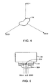
- FIGS. 2 and 3 illustrate a method 200 of determining a radiation treatment plan that may be used by the system 10.
- the method 200 will be described with reference to treating a target region TR using a radiation source 20 that rotates about the target region TR (e.g., 360° about the target region TR), as in an arc therapy ( FIG. 4 ).
- the method 200 is not limited to the example illustrated in FIG. 4 , and that the method 200 may be used to determine other treatment plans with a different setup.
- the method 200 may be used to determine a treatment plan in which the radiation source 20 does not rotate completely about the TR, but only partially (e.g., less than 360° about the patient 28).
- a dose calculation point is used to represent a component that is a part of a divided treatment.
- the total dose of a treatment may be divided into components.
- a broadly defined dose calculation point contains the dose delivered during some part of the treatment. The sum of doses from all dose calculation points is the total dose of the treatment.
- the division of the treatment into components may be done with respect to various parameters in different embodiments. In the illustrated example, the treatment is initially divided into three components represented by dose calculation points DC1, DC2, DC3, wherein the division is done with respect to the gantry angles such that DC1, DC2, DC3 represent respective 120° gantry ranges ( FIG. 4 ).
- Division of a treatment based on gantry angles may be useful in determining treatment plans for arc treatments.
- the number of dose calculation points may be different from three. For example a 360° treatment can be divided into 10° components, in which case, the number of dose calculation points would be 36. Each component would cover the dose delivered in different 10° gantry angle intervals.
- the dose calculation points instead of having each dose calculation point representing an interval with a same range, the dose calculation points may represent respective intervals with different ranges (e.g., DC1 may represent gantry angles from 0°-180°, DC2 may represent gantry angles from 180°-300°, and DC3 may represent gantry angles from 300°-360°).
- the radiation can be modeled by assuming radiation coming from one fixed gantry angle.
- the dose can be calculated by assuming that all radiation in this 0° to 120° interval is coming from 60° angle. It is easier and faster to calculate the dose from a single fixed ganty angle than from a curved path from °0 to 120°.
- Fluence is the amount of radiation passing through a spatial region, and may be represented by a fluence map.
- a fluence map is a matrix that covers a spatial region (e.g., a plane). For each point in the plane, the fluence map defines the amount of radiation passing through that element.
- FIG. 5 illustrates an example of a fluence map.
- the radiation source sends radiation with strength 2.
- There is a block 502 (which may be, for example, a leaf of a collimator) in the middle of radiation beam blocking half of the radiation passing through that block.
- the 502 block may be extended half way to allow radiation to pass through half of a prescribed region.
- the block 502 may be retracted to let radiation pass through the region half the time, and may be closed completely to prevent radiation from passing through the region the other half the time.
- the fluence in the fluence plane is 0 in parts where the collimator leaves 504 block the radiation to prevent the radiation from passing through.
- the fluence is 2 where all the radiation from source reaches (and passes through) fluence plane.
- the fluence is 1 where half of the radiation was blocked by the 502 block.
- the matrix of fluence elements form a fluence map 00002120000.
- a computer user interface such as a screen and an input device, may be provided for allowing a user to input data for defining dose calculation points.
- the screen may display one or more input fields for allowing the user to input the data, such as number of dose calculation points, and treatment division parameters.
- the screen may also display input fields for allowing user to input target region size, target region shape, maximum allowable dose, minimum required dose, etc.
- the displaying of the input fields may be done in response to a processor (which may be the same processor 54, or a separate processor) and/or software executing a set of instruction. In such cases, the processor and/or the software determines the dose calculation points by receiving input by the user.
- the processor and/or the software performs optimization using the three defined dose calculation points DC1, DC2, DC3 (Step 204).
- the regions represented by respective dose calculation points DC1, DC2, DC3 are modeled with respective fluence maps.
- the processor and/or software runs the fluence optimization for some number of iterations (e.g., 100).
- the objective of the optimization is to get fluence maps that produce best dose in patient 28 by optimizing the individual components in the fluence maps.
- the optimization objective may be defined using DVH (dose volume histogram) constraints in patient dose.
- Dose volume histogram is a graph (function) DVH(x) that tells which fraction of a defined volume receives less than x dose
- DVH constraint is a constraint that describes which shapes of DVH are preferred.
- a user may specify (e.g., using a user interface) not to put more than 30 Gy dose to spine, but to keep the dose in target between 60 and 70 Gy.
- the objective is to find out the best fluence map configuration at the various dose points that will give the desired dose at the target, while minimizing dose to healthy tissue outside the target.
- DVH function and constraints are well known in the art.
- Step 206 the method moves to dose calculation point level 2, in which the interval for each dose calculation point is halved such that the treatment is modeled in six intervals.
- the division can be done by assuming that two adjacent dose calculation points at level 2 have the same fluence as the parent fluence map at level 1. So the dose calculation points DC1 and DC2 at level 2 would have a fluence map that is equal to the fluence map of dose calculation point DC1 at level 1 times 0.5.
- Step 206 six dose calculation points are modeled with six fluence maps.
- the processor and/or the software runs a number (e.g., 100) of iterations of fluence optimization again, this time using the dose calculation points DC1 - DC6 at level 2 (Step 208).
- the objective of the optimization is to get fluence maps that produce best dose in patient 28 by optimizing the individual components in the fluence maps for the six dose calculation points DC1-DC6.
- the technique for performing the optimization in step 208 may be the same as that described with reference to step 204.
- the complexity of all fluences at level 2 is then evaluated (Step 210).
- Various techniques may be used to evaluate the complexity of a fluence at any given level.
- the complexity of a fluence is represented by the complexity of its corresponding fluence map.
- the complexity of the fluence map is calculated by converting the fluence map to machine parameters, and calculating the time required to move the leaves based on the machine parameters. The more the time that is required to move the leaves to achieve a fluence profile, the more complex is the fluence.
- other parameters may also be used.
- the number of leaves that need to be moved in order to achieve a fluence may also be used to determine the complexity of the fluence.
- the more the number of leaves that need to be moved the more the complex the fluence.
- the distance that the leaf(s) need to travel may also be used to determine the complixity of the fluence. In such cases, the more the distance, the more the complex the fluence.
- any combination of the above parameters and/or other parameters not described herein may be used to determine a complexity of a fluence.
- FIG. 6 illustrates an example of converting a fluence map 600 to machine parameters using a leaf sequencing technique.
- the leaves would first be closed 602a at time step 1. Then the leaves would be open in the regions shown in the leaf configuration 602b at time step 2. Then the leaves would be open in the regions shown in the leaf configuration 602c at time step 3. Then the leaves would be closed again 602d (time step 6).
- the fluence components 604a-604d for the respective leaf positions 602a-602d are also shown. As shown in the figure, the sum of the fluence components 604a-604d equals the fluence map 600. In the illustrated example, the most complex region is in the dose calculation point 5 at level 2 ( FIG. 3 ). Thus, the processor and/or software converts all of the fluence to machine parameters, except that for dose calculation point 5. In some cases, the processor and/or software determines whether a level of complexity of a fluence is below a prescribed threshold, and converts the corresponding fluence map to one or more machine parameters for the dose calculation point when it determines that the level of complexity is below the prescribed threshold.
- the processor and/or software determines whether a level of complexity of a fluence is above a prescribed threshold, and converts the corresponding fluence map to one or more machine parameters for the dose calculation point when it determines that the level of complexity is above the prescribed threshold.
- each of the leaf positions 602a-602d is a machine parameter that corresponds with a machine control point.
- the term "machine control point” or “control point” refers to a component of a treatment plan that includes one or more machine parameters for prescribing a part of the treatment plan.
- a treatment plan may be prescribed using N number of machine control points, each of which contains machine parameter(s) (such as any or a combination of: gantry speed, gantry angle, beam-on/activation signal, beam-off/deactivation signal, collimator position, leaves' positions, couch position, beam energy, beam type, dose (or monitor units), and dose rate (or beam intensity)) for defining a part of the treatment plan.
- machine parameter(s) such as any or a combination of: gantry speed, gantry angle, beam-on/activation signal, beam-off/deactivation signal, collimator position, leaves' positions, couch position, beam energy, beam type, dose (or monitor units), and dose rate (or beam intensity)
- the number of machine control points that correspond with a fluence map may vary. For example, a complex fluence map may be converted into a higher number of leaves' positions (machine control points), while a simpler fluence map may only require fewer machine control points to achieve the desired fluence. In some cases, the total number of machine control points in a complete treatment plan may be in the range of hundreds or even thousands. The number of machine control points are higher than the number of dose calculation points. However, the dose at the dose calculation point is used to evaluate the machine parameters, thereby obviating the need to calculate dose for each of the machine control points, which in some cases, may take up a significant amount of computation time and resources. It has been discovered that determining dose at dose calculation points without doing the same at all of the machine control points can achieve a treatment plan that is sufficiently accurate.
- FIG. 7 illustrates an example of converting a fluence map 700 to machine parameters using a leaf sequencing technique.
- the fluence represented by the fluence map 700 can be converted to radiation source positions (another example of machine parameters), which in the example, has four radiation source positions 702a-702d at respective four time points.
- the radiation source would first be placed at positions 702a-702d at respective time steps 1-4.
- the fluence components 704a-704d for the respective radiation source positions 702a-702d are also shown.
- the sum of the fluence components 704a-704d equals the fluence map 700.
- each of the radiation source positions 702a-702d corresponds with a machine control point.
- the number of machine control points that correspond with a fluence map may vary.
- a complex fluence map may be converted into a higher number of radiation source positions (machine control points), while a simpler fluence map may only require fewer machine control points to achieve the desired fluence.
- the radiation source is illustrated as translating. However, the same principle can be used with a radiation source 20 that rotates, with each time step corresponding to one machine control point.
- the number of machine control points for each dose calculation point is constant. In other embodiment, the number of machine control points may be different for different dose calculation points, depending on the complexity of the fluence for the particular dose calculation point. Regardless of the number of machine control points, the dose calculation is always performed at the dose calculation points. There will be some error because the angle changes during rotation, but the error could be acceptable if the separation of final dose calculation points is small enough. For example there could be one dose calculation points every 1 or 2 degrees, but within that 1 or 2 degree range, there could be 1, 2, 3, 10, or 100 machine control points. It would be a waste of computation time to calculate the dose with 1/100 degree interval, because that level of accuracy is not required. The change in fluence may be significant due to leaf movement, but the change due to angular rotation may be too small to justify calculating dose at every machine control point.
- Step 214 the optimization is continued (Step 214).
- gradient back projection technique is used in the optimization for fluence maps
- direct aperture method is used in the optimization for regions modeled with machine control points.
- the derivatives of the objective function with respect to change in fluence are calculated in gradient map. It is called gradient back projection because the gradients are calculated in some volume elements, and the derivatives of the objective function at those volume elements are projected back and summed to fluence plane to form a gradient plane.
- the fluence is modified by adding the gradient plane to fluence plane (first the gradient plane values are multiplied by some scalar, because the scale is different).
- Direct aperture methods refer to directly modeling the treatment in machine parameters, wherein the gradient of objective function is calculated with respect to machine parameters and the machine parameters are changed according to the gradients.
- the objective function gradient is calculated with respect to the fluence sum elements
- the objective function gradient is calculated with respect to leaf positions ( FIG. 6 ).
- the dose is still calculated at dose calculation points.
- the average fluence from machine control points is accumulated at dose calculation point, and the dose is assumed to come from the dose calculation point.
- the optimization objective of the optimization in step 214 is the same as that described previously.
- the machine control points are modified so that they produce a desired fluence in the corresponding dose calculation point (which may represents a range of gantry angles for positions of the radiation source). The goal is to produce an optimal radiation fluence.
- the optimization in step 214 utilizes an iterative technique in which more and more dose calculation points are progressively converted into machine parameters as the number of iterations increases.
- the process 200 may repeat the step of converting fluence to machine parameters (Step 212) and the step of optimization (Step 214) until all of the dose calculation points (except the ones with the most complex fluence) modeled with fluence maps are converted to machine parameters at machine control points.
- the determined machine parameters are based on the complexity of fluence from other directions. Therefore the more demanding leaf movements have been considered, except for the range 240 - 300 corresponding with dose calculation point 5 at level 2 ( FIG. 3 ). For this range, because there is limited time to move leaves to achieve a complex fluence, the resulting fluence may only be partially accomplished.
- the processor and/or software uses a slower gantry rotation to determine the portion of the treatment that corresponds with this gantry range. With slower gantry rotation, there is more time to move the leaves and the more complex fluence can be converted to machine parameters more accurately (Step 216).
- the processor and/or software can also use more control points (e.g., more machine control points and/or more dose calculation points) for the complex region(s). Such technique will also allow the more complex fluence to be accomplished more accurately.
- different maximum speeds of gantry rotation may be prescribed for different gantry ranges / intervals. In such cases, the machine parameters are determined for the corresponding control points based on the prescribed maximum speed for the corresponding gantry range / interval.
- the processor and/or software performs optimization again using the machine parameters for all of the dose calculation points (Step 218).
- the objective of this optimization is to fine tune the previously determined machine parameters such that they produce the desired fluence at the various dose calculation points.
- the resulting machine parameters for the machine control points are then stored as a treatment plan in a medium for later use (Step 220).
- the method 200 may go one level further, e.g., to level 3, where dose calculation points are increased such that the dose calculation points and machine control points could coincide, but this is not always necessary. This is because the treatment is modeled using final accuracy of machine control points inside the dose calculation point and keeping the machine control points valid (so that the machine would be able to deliver the treatment as presented in machine control points). However, the dose is not calculated from the direction of all machine control points. The total radiation fluence from all of the machine control points belonging to one dose calculation points is first calculated (this is a fast step). Then the dose in patient is calculated from the fluence map in control point. Therefore the part of the treatment modeled as machine control points is a valid treatment. The division to even more dose calculation points is done to decrease another source of error in dose calculation.
- the processor and/or software evaluates the complexity of fluence in order to determine which control points to change in an iteration, and the conversion starts from most simple interval.
- the conversion may be based on a different technique. For example, in other embodiments, the conversion may start from most complex interval. Such technique would allow the optimizer to determine the most difficult conversion problems early on in the optimization process.
- the processor and/or software may use spatial order. For example, control points in first range of angles 0° - 10° may be converted, then control points for angles 10° - 20° are converted, and then the control points for angles 20° - 30° are converted. This technique removes the connectivity problem of machine parameters.
- the initial number of dose calculation points is small, and is then increased progressively (e.g., from dose calculation level 1 to dose calculation level 2) as the treatment plan is refined.
- the optimization may be accomplished faster because the total dose can be evaluated more quickly using fewer number of dose calculation points.
- the leaf sequencing may be accomplished easier because there is more time (the treatment time modeled in a dose calculation interval is longer) for the leaves to move to produce the desired fluence.
- the fluence maps are desired to be converted to machine parameters. The conversion is not perfect - i.e., because of machine limitation, some parts of the resulting fluence may be different from that calculated at the dose calculation points.
- the process could first model all intervals of the treatment using fluence maps. Then one or more of the fluence maps are converted to machine parameters. Optimization is continued, in which fluence optimization is used for intervals modeled by fluence maps, and direct machine parameter optimization is used for intervals that are modeled by machine parameters. The errors resulting from the conversion are decreased very efficiently by other intervals modeled by fluence maps. In such technique, more and more intervals are converted to machine parameters as the optimization progresses. Finally the treatment is modeled by machine parameters.
- the method 200 may include additional dose calculation point level(s).
- the dose calculation points may increase at any part of the method 200.
- the method 200 can repeat steps 206, 208 to increase dose calculation points and perform optimization at any time during the method 200 (See arrows 230, 240, 250 in FIG. 2 ).
- the method 200 may include only one dose calculation point level. In such cases, steps 206, 208 may be omitted.
- the optimization used by the method 200 is an iterative technique, in which cases, the number of dose calculation points may be increased at any one of the iterations.
- the process 200 initially models parts of a treatment (e.g., an arc treatment) in 120° intervals of gantry angles with fluence maps.
- the treatment may be modeled in other intervals (e.g., 1°, 5°, 10°, etc.) of gantry angles.
- the treatment may be modeled initially using fluence maps for some intervals, and machine parameters (e.g., leaf positions) for other intervals.
- the treatment may be divided into components, for example in 10 degree intervals in gantry angle, in which the first three intervals may be modeled by fluence maps and the rest of 33 intervals with direct machine parameters. Both modeling techniques to present part(s) of treatment have their advantages.
- a fluence map can very efficiently represent radiation from some direction and there are very efficient optimization methods to find good fluence maps. However, in some cases, it may be difficult to model machine limitations with fluence map optimization. On the other hand, if a part of the treatment in an interval is modeled using machine parameters, it is easier to apply machine limitations in optimization. However, these optimization methods may be slower, more constrained, and may be more easily trapping into a local minima.
- the division of the treatment into components is done with respect to the gantry angles. In other examples, the division of the treatment into components may be done with respect to other parameters.
- the dose calculation points may be defined so that they correspond with respective time. For example a 60 second treatment can be divided into 6 dose calculation points. First dose calculation point would cover the dose delivered from 0 second to 10 second, second dose calculation point from 10 second to 20 second, and so on.
- the dose calculation points may be defined so that they correspond with monitor units.
- Monitor units is the amount of radiation units produced by the machine 10.
- a 600 MU treatment may be divided into 3 dose calculation points. First dose calculation point would cover the dose delivered from 0 to 200 MU, second dose calculation point would cover the dose delivered from 200 to 400 MU, and third dose calculation point would cover the dose delivered from 400 to 600 MU.
- the dose calculation points may be defined so that they correspond with respective regions of the patient 28 (e.g., different parts of a target region).
- the dose calculation points may be defined such that they correspond to some other geometric parameters.
- the dose calculation points may be defined such that they correspond with respective positions of the support 14 (e.g., couch) along its longitudinal axis, with respective angles of the support 14, or respective collimator angles.
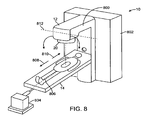
- FIG. 8 illustrates another embodiment of a radiation system 10 in which the patient support 14 is translatable.
- the system 10 includes a gantry 12 having an arm 800, a support structure 802 to which the gantry is rotatably coupled, and a radiation source 20.
- the patient support 14 is coupled to a positioner 804, which is for translating the patient support 14 in a back and forth manner.
- the radiation source 20 rotates at least partially around the patient 28 so that radiation can be delivered to target region from a plurality of gantry angles.
- the positioner 804 moves the patient support 14 along the longitudinal axis 806 (the Z-axis) forward 808 and backward 810, so that different parts of the target region along the axis 806 may receive radiation from a plurality of gantry angles.
- the system 10 of FIG. 8 is advantageous for treating target that cannot be irradiated with one gantry rotation using existing systems.
- the system 10 may be used to perform whole body irradiation or irradiation of long tumor near spine with one continuous radiation trajectory.
- providing back and forth trajectories is desirable in that it results in control points that represent independent degrees of freedom in the optimization that have independent constraints.
- translating the patient support 14 in a back and forth manner during a treatment saves time.
- the trajectory is simple and easy to understand spatially, and saves treatment planning time. This allows the trajectory to be evaluated easily, and used for many purposes.
- the radiation source 20 may be stationary while the patient support 14 is translated back and forth. This allows radiation to be modulated along the axis 806 such that different parts of the target region along the axis 806 receives different amount of radiation (i.e., for a given gantry angle).
- the above described trajectory also allows collision between radiation device and patient 28 / support 14 to prevented more easily. This is because in the above described trajectory, the radiation source moves relative to the patient 28 and support 14 in paths that form a cylinder. Cylinder is relatively easy to understand spatially, and therefore, a user may more easily evaluate a risk of collision for such trajectory than for a more complex trajectory.
- the system 10 uses a collision prevention mechanism that involves comparing an image of the patient 28 and the support 14 with a cylinder / ring with a specific radius, and checking to see if the cylinder / ring collides with the patient 28 or support 14. Because the support 14 moves back and forth along the same route, the collision detection cylinder will be the same for all passes. This simplifies the collision detection.
- the radiation source 20 may be translatable in the Z-axis direction. In either case, the patient support 14 and the radiation source 20 may be considered as moveable or translatable relative to each other.
- the radiation source 20 may be configured to tilt about an axis (e.g., axis 812) that forms an angle (e.g., 90°) relative to the longitudinal axis 806. During use, the radiation source 20 tilts about the axis 812 so that radiation may be delivered to different parts of the target region along the axis 806. The radiation source 20 also rotates at least partially around the patient 28 so that it can deliver radiation to the target region from a plurality of gantry angles.
- FIG. 9 illustrates another embodiment of a radiation system 10 in which the patient support 14 is configured to rotate in correspondence with the rotation of the radiation source 20.
- the patient 28 with the support 14 is shifted away from the isocenter 900.
- the radiation source 20 rotates at least partially along path 902 to deliver radiation to the patient 28 from a plurality of gantry angles.
- the patient support 14 is configure (e.g., using a positioner) to rotate at least partially along path 904.
- the radiation source is moved to another gantry position (represented by reference numeral 20'), and accordingly, the support and the patient are moved around spatial region 908 such that the support and the patient is at operative positions (represented by reference numerals 14', 28') opposite from the radiation source.
- Such configuration is beneficial in that it provides relatively more room between the patient 28 and the radiation source 20, thereby allowing bigger and heavier patient (which may otherwise be impossible if the support 14 is closer to the isocenter) to be treated.
- Such feature is also advantageous in that it allows the patient 28 who is being treated to feel more comfortable (especially if the patient 28 is claustrophobic), and reduces the risk of having the patient 28 / support 14 collide with the radiation source 20.
- the radiation source 20 and the patient support 14 both rotates at least partially around a spatial region 908, and about an axis (which may coincide with, or locate next to, isocenter 900).
- the term “around” e.g., as in "around a spatial region” is not limited to movement by the support 14 or source 20 that is in an arc or circular path, and that the term “around” may refer to movement by the support 14 or source 20 that is in other path shapes in different embodiments, as long as the trajectory of the support 14 or source 20 forms a loop that surrounds the spatial region, or a partial loop (e.g., an arc that is less than 360°) that partially surrounds a part of the spatial region.
- the radiation source 20 and the patient support 14 may rotate about different respective axes that are parallel to, and spaced apart from, each other.
- FIG. 10 illustrates a patient support system 1000 that may be used to move the patient support 14 in the manner described in the embodiment of FIG. 9 .
- the patient support system 1000 includes a base 1002, an arm 1004, and the patient support 14.
- the arm 1004 has a first end 1006 that is rotatably coupled to the base 1002, and a second end 1008 that is rotatably coupled to the support 14.
- the arm 1004 is rotable about an axis 1010 relative to the base 1002, and is also rotatable about another axis 1012 relative to the support 14.
- a positioning device e.g., a motor
- the support 14 is rotated relative to the arm 1004 about the axis 1012 such that the support surface of the support 14 always faces upward while the support 14 is rotated about the axis 1010.
- the patient support system 1000 may further include a positioning device coupled between the support 14 and the arm 1004 for translating the support 14 back and forth along axis 1014. This allows the patient support system 1000 to be used in a similar manner as that described with reference to FIG. 8 .
- the patient support system 1000 is not limited to the configuration described previously, and that the patient support system 1000 may have other configurations (e.g., may have different degrees of freedom) in other embodiments, as long as the patient support 14 can move at least partially around the patient 16.
- any of the trajectories described herein may be used in the treatment planning method 200 described with reference to FIG. 2 .
- the method 200 may involve defining a parameter that corresponds with rotation of the patient support 14.
- the rotation parameter may be optimized during the method 200 (e.g., in step 204, 208, 214, and/or 218).
- the method 200 may involve defining a parameter that corresponds with a translation of the patient support 14.
- the translation parameter may be optimized during the method 200 (e.g., in step 204, 208, 214, and/or 218).
- providing back and forth trajectories is desirable in that it results in control points that represent independent degrees of freedom in the optimization that have independent constraints.
- the term "optimization" refers to the act of making something better, which may involve changing a value of a parameter, wherein the changing of the value may be performed manually by a user, or automatically using an optimization software.
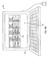
- FIG. 11A illustrates an example of a user interface 1100 that may allow a user to determine a treatment plan in accordance with some embodiments.
- the term "user” may refer to a single person, or a plurality of persons.
- the user interface 1100 may be used in the method 200 to determine a treatment plan.
- the user interface 1100 includes a screen 1102 displaying an input interface 1104.
- the input interface 1104 may be generated by a processor that executes a set of instruction programmed to provide the image of the input interface 1104.
- the input interface 1104 includes a table 1106 having fields that allow the user to input parameters and/or values.
- control points 1108 parameter 1110 for the allowable starting point of support 14, parameter 1112 for allowable ending point of support 14, parameter 1114 for allowable gantry starting angle, and parameter 1116 for allowable gantry ending angle.
- a control point may represent a single point (e.g., "0,” “1,” "2"), or an interval between two points (e.g., "0-1 interval,” "1-2 interval”).
- the table 1106 includes various input fields for allowing the user to input values for the parameters at different control points.
- a value may be a numerical value, or an instruction (e.g., "interpolate" - which specifies that values for the corresponding control point are to be calculated in accordance with a prescribed scheme).
- the user needs not enter all or any value for the input fields.
- the processor / software for determining the treatment plan is configured to determine the values for the various fields in the table 1106.
- the trajectory is defined by the control points 108, wherein each control point 108 defines a region in parameter space.
- the optimized trajectory has to pass through the defined region before proceeding to the next control point 108.
- the allowed region (range of parameters) between the control points is also defined.
- the control points define the region where the machine control points must be placed.
- the processor / software for determining the treatment plan is configured to generate machine control points based on these rules and the defined parameters. For example, as similarly discussed with reference to FIG. 2 , the processor / software may perform optimization based on geometric properties of target region(s) and healthy region(s). The processor / software may then continue with the optimization using dose based method(s), e.g., direct aperture method, or fluence based method.
- dose based method(s) e.g., direct aperture method, or fluence based method.
- the user interface 1100 allows the user to input initial values for some or all of the parameters.
- the processor / software optimizes the values based on certain user-defined constraints (e.g., size, shape, and location of target, path of source, etc.).
- the processor / software may be configured to determine the values for the parameters without any initial input values from the user.
- the trajectory would move the support 14 from 0 cm to 40 cm in the Z direction (from control point 0 to control point 1), and back to 0 cm (from control point 1 to control point 2).
- the gantry 12 would rotate° from somewhere between 0° and 45° to between 315° and 360°, and back to between 0° and 45°.
- the Z-positions of the support 14 would be interpolated (e.g., linearly, or using some other interpolation scheme) between the control points.
- the optimizer of the processor / software that is used to perform method 200 is configured to determine the route between the control points for gantry angles in the 0° to 360° interval.
- the user interface 1100 also allows the user to perform simple operations on defined trajectory.
- the trajectory of FIG. 11A may be stretched in the Z-direction by applying a multiplication of 2 in the Z-direction of the support 14. After the multiplication operation, the trajectory would be that shown in FIG. 11 B. In other embodiments, at least part of the trajectory may be shifted.
- the support 14 may be translated in the Z-direction by -20 cm from the trajectory of FIG. 11B , which will result in the trajectory of FIG. 11C .
- the range of relative motion between the support 14 and the radiation source can be a value that is between 5 cm and 50 cm. This range is adequate if the target is one connected region. In other embodiments, if the target includes multiple regions (e.g., which may be separated from each other) desired to be treated, then the range of relative motion between the patient support 14 and the radiation source could be anywhere between 5 cm and 2m.
- the user interface 1100 allows the user to save the designed trajectory in a medium.
- the trajectory may be saved as a part of a treatment plan, which will be used later in a treatment procedure.
- the trajectory may be saved as a trajectory class.
- the trajectory classes may be organized based on specific machines (e.g., different machines may have different classes of trajectories), patient anatomy, location of target regions, sizes of target regions, shapes of target regions, and/or other disease specific factors. In such cases, a user may retrieve a trajectory from one of the available trajectory classes, based on the specific machine, target region's shape, size, and location, and type of disease.
- the user may then revise the retrieved trajectory to fine-tune it so that is can be better used for a specific treatment for a specific patient.
- the user may perform a multiplication and/or an adding procedure for any part (e.g., a parameter type) of the trajectory, such as those discussed with reference to FIGS. 11B and 11C , to thereby fit the dimensions and/or positions of a target in a specific patient.
- the type of parameters that may be defined using the user interface 1100 is not limited to the example discussed, and that the user interface 1100 may allow the user to define other parameters, such as gantry angle, positions (e.g., x, y, z) of support 14, orientations ( ⁇ x , ⁇ y , ⁇ z ) of support 14, dose (e.g., user may specify whether dose is to be delivered for a control point), dose rate, leaves' positions, and speed limits (e.g., of gantry rotation, leaves movements, support 14 movements, etc.).
- positions e.g., x, y, z
- orientations ⁇ x , ⁇ y , ⁇ z
- dose e.g., user may specify whether dose is to be delivered for a control point
- dose rate e.g., user may specify whether dose is to be delivered for a control point
- leaves' positions e.g., gantry rotation, leaves movements, support 14 movements, etc.
- the user interface 1100 provides a flexible method for a planner to communicate to the optimizer which class of trajectories is considered for a specific case.
- the trajectory is defined as a set of control points, in which some parameters are to be optimized, and other parameters are to be interpolated. In some embodiments, parameters that are not optimized are interpolated using an interpolation scheme.
- the user interface 1100 also allows ranges to be defined, and provides tools for a user to manipulate the trajectory class. In some cases, the parameters to be optimized may be different for different intervals of the treatment.
- the user interface 1100 provides a tool for allowing a user to define a trajectory that is flexible enough for different applications, and is easy to converge to a good solution (because not all of the parameters need to be optimized - some of the parameters may be interpolated).
- the system and technique described herein may be used for other types of treatment energy.
- the radiation source 20 may be a proton source for delivering protons to treat a patient, or an electron source for delivering electrons.
- embodiments of the treatment planning technique described herein may be used to determine treatment plan for other types of treatment, such as proton treatment.
- the term "collimator" is not limited to a device having leaves for blocking radiation, and may refer to a device having one or more jaws or jaw blocks.
- a position of a collimator may refer to position of leaves of a collimator, position of collimator jaws, or a global position of the collimator itself relative to some coordinate system (e.g., a position of the collimator relative to a gantry or relative to a radiation machine, etc.).
- FIG. 12 is a block diagram that illustrates an embodiment of a computer system 1200 upon which an embodiment of the invention may be implemented.
- Computer system 1200 includes a bus 1202 or other communication mechanism for communicating information, and a processor 1204 coupled with the bus 1202 for processing information.
- the processor 1204 may be an example of the processor 54 of FIG. 1 , or another processor that is used to perform various functions described herein. In some cases, the computer system 1200 may be used to implement the processor 54.
- the computer system 1200 also includes a main memory 1206, such as a random access memory (RAM) or other dynamic storage device, coupled to the bus 1202 for storing information and instructions to be executed by the processor 1204.
- main memory 1206 such as a random access memory (RAM) or other dynamic storage device
- the main memory 1206 also may be used for storing temporary variables or other intermediate information during execution of instructions to be executed by the processor 1204.
- the computer system 1200 further includes a read only memory (ROM) 1208 or other static storage device coupled to the bus 1202 for storing static information and instructions for the processor 1204.
- ROM read only memory
- a data storage device 1210 such as a magnetic disk or optical disk, is provided and coupled to the bus 1202 for storing information and instructions.
- the computer system 1200 may be coupled via the bus 1202 to a display 1212, such as a cathode ray tube (CRT), for displaying information to a user.
- a display 1212 such as a cathode ray tube (CRT)
- An input device 1214 is coupled to the bus 1202 for communicating information and command selections to processor 1204.
- cursor control 1216 is Another type of user input device
- cursor control 1216 such as a mouse, a trackball, or cursor direction keys for communicating direction information and command selections to processor 1204 and for controlling cursor movement on display 1212.
- This input device typically has two degrees of freedom in two axes, a first axis (e.g., x) and a second axis (e.g., y), that allows the device to specify positions in a plane.
- the computer system 1200 may be used for performing various functions (e.g., calculation) in accordance with the embodiments described herein. According to one embodiment, such use is provided by computer system 1200 in response to processor 1204 executing one or more sequences of one or more instructions contained in the main memory 1206. Such instructions may be read into the main memory 1206 from another computer-readable medium, such as storage device 1210. Execution of the sequences of instructions contained in the main memory 1206 causes the processor 1204 to perform the process steps described herein. One or more processors in a multi-processing arrangement may also be employed to execute the sequences of instructions contained in the main memory 1206. In alternative embodiments, hard-wired circuitry may be used in place of or in combination with software instructions to implement the invention. Thus, embodiments of the invention are not limited to any specific combination of hardware circuitry and software.
- Non-volatile media includes, for example, optical or magnetic disks, such as the storage device 1210.
- Volatile media includes dynamic memory, such as the main memory 1206.
- Transmission media includes coaxial cables, copper wire and fiber optics, including the wires that comprise the bus 1202. Transmission media can also take the form of acoustic or light waves, such as those generated during radio wave and infrared data communications.
- Computer-readable media include, for example, a floppy disk, a flexible disk, hard disk, magnetic tape, or any other magnetic medium, a CD-ROM, any other optical medium, punch cards, paper tape, any other physical medium with patterns of holes, a RAM, a PROM, and EPROM, a FLASH-EPROM, any other memory chip or cartridge, a carrier wave as described hereinafter, or any other medium from which a computer can read.
- Various forms of computer-readable media may be involved in carrying one or more sequences of one or more instructions to the processor 1204 for execution.
- the instructions may initially be carried on a magnetic disk of a remote computer.
- the remote computer can load the instructions into its dynamic memory and send the instructions over a telephone line using a modem.
- a modem local to the computer system 1200 can receive the data on the telephone line and use an infrared transmitter to convert the data to an infrared signal.
- An infrared detector coupled to the bus 1202 can receive the data carried in the infrared signal and place the data on the bus 1202.
- the bus 1202 carries the data to the main memory 1206, from which the processor 1204 retrieves and executes the instructions.
- the instructions received by the main memory 1206 may optionally be stored on the storage device 1210 either before or after execution by the processor 1204.
- the computer system 1200 also includes a communication interface 1218 coupled to the bus 1202.
- the communication interface 1218 provides a two-way data communication coupling to a network link 1220 that is connected to a local network 1222.
- the communication interface 1218 may be an integrated services digital network (ISDN) card or a modem to provide a data communication connection to a corresponding type of telephone line.
- ISDN integrated services digital network
- the communication interface 1218 may be a local area network (LAN) card to provide a data communication connection to a compatible LAN.
- LAN local area network
- Wireless links may also be implemented.
- the communication interface 1218 sends and receives electrical, electromagnetic or optical signals that carry data streams representing various types of information.
- the network link 1220 typically provides data communication through one or more networks to other devices.
- the network link 1220 may provide a connection through local network 1222 to a host computer 1224 or to equipment 1226 such as a radiation beam source or a switch operatively coupled to a radiation beam source.
- the data streams transported over the network link 1220 can comprise electrical, electromagnetic or optical signals.
- the signals through the various networks and the signals on the network link 1220 and through the communication interface 1218, which carry data to and from the computer system 1200, are exemplary forms of carrier waves transporting the information.
- the computer system 1200 can send messages and receive data, including program code, through the network(s), the network link 1220, and the communication interface 1218.
Landscapes
- Health & Medical Sciences (AREA)
- Engineering & Computer Science (AREA)
- Biomedical Technology (AREA)
- General Health & Medical Sciences (AREA)
- Public Health (AREA)
- Nuclear Medicine, Radiotherapy & Molecular Imaging (AREA)
- Veterinary Medicine (AREA)
- Animal Behavior & Ethology (AREA)
- Pathology (AREA)
- Life Sciences & Earth Sciences (AREA)
- Radiology & Medical Imaging (AREA)
- Surgery (AREA)
- Urology & Nephrology (AREA)
- Epidemiology (AREA)
- Medical Informatics (AREA)
- Primary Health Care (AREA)
- Radiation-Therapy Devices (AREA)
Claims (15)
- System zur Erstellung eines durch einen oder mehrere Parameter definierten Bestrahlungsplans, das eine Verarbeitungseinheit (54) umfasst, die für Folgendes konfiguriert ist:Erlangen von Dosisberechnungspunkten (DC1-DC6), wobei jeder der Dosisberechnungspunkte ein Parameterintervall darstellt;Berechnen der Dosis an den Dosisberechnungspunkten (DC1-DC6), wobei mindestens einer der Dosisberechnungspunkte einer Vielzahl von entsprechenden Kontrollpunkten zugeordnet ist, und eine Gesamtzahl von Dosisberechnungspunkten unter einer Gesamtzahl von Kontrollpunkten liegt, wobei mindestens einer der Kontrollpunkte einer Fluenz des Bestrahlungsplans zugeordnet ist; undDurchführen einer Optimierung, die das Ändern einer Anzahl von Dosisberechnungspunkten (DC1-DC6) einschließt.
- System nach Anspruch 1, wobei die Verarbeitungseinheit (54) ferner zum Ändern einer Anzahl der Kontrollpunkte konfiguriert ist.
- System nach Anspruch 1 oder 2, wobei der eine oder die mehreren Parameter Lamellensequenz, Kollimatorstellung, Gantry-Rotationsgeschwindigkeit, Gantrystellung, Liegestellung, Strahlaktivierungssignal, Strahldeaktivierungssignal, Dosis, Dosisrate, Strahlenergie und Strahlenart umfasst bzw. umfassen.
- System nach einem der Ansprüchen 1 bis 3, wobei die Verarbeitungseinheit (54) zum Durchführen eines iterativen Optimierungsprozesses konfiguriert ist.
- System nach Anspruch 4, wobei die Verarbeitungseinheit (54) dazu konfiguriert ist, die Anzahl der Dosisberechnungspunkte (DC1-DC6) in einer Iteration zu ändern.
- System nach einem der Ansprüche 1 bis 5, wobei Kontrollpunktbereiche unterschiedliche maximale Gantry-Rotationsgeschwindigkeiten aufweisen.
- System nach einem der Ansprüche 1 bis 6, wobei das Parameterintervall für jeden Dosisberechnungspunkt (DC1-DC6) jeweiligen Gantrybereichen, Zeiträumen oder Überwachungseinheiten entspricht.
- System nach einem der Ansprüche 1 bis 7, wobei das Parameterintervall für jeden Dosisberechnungspunkt (DC1-DC6) einer jeweiligen Region eines Patienten, einem jeweiligen Kollimatorwinkel, einer jeweiligen Lagerungshilfestellung oder einem jeweiligen Lagerungshilfewinkel entspricht.
- System nach einem der Ansprüche 1 bis 8, wobei die Verarbeitungseinheit (54) zum Modellieren eines ersten Teils des Bestrahlungsplans mithilfe einer Fluenzverteilung und zum Modellieren eines zweiten Teils des Bestrahlungsplans mithilfe eines ersten Parameters konfiguriert ist.
- System nach Anspruch 9, wobei die Fluenzverteilung eine Matrix umfasst, die ein einen räumlichen Bereich durchlaufendes Strahlungsvolumen darstellt.
- System nach Anspruch 9 oder 10, wobei der erste Parameter aus der Gruppe ausgewählt ist, die Lamellensequenz, Kollimatorstellung, Gantry-Rotationsgeschwindigkeit, Gantrystellung, Liegestellung, Strahlaktivierungssignal, Strahldeaktivierungssignal, Dosis, Dosisrate, Strahlenergie und Strahlenart umfasst.
- System nach Anspruch 9, 10 oder 11, wobei die Verarbeitungseinheit (54) ferner zur Konvertierung von mindestens einem Teil der Fluenzverteilung in einen zweiten Parameter konfiguriert ist.
- System nach einem der Ansprüche 9 bis 12, wobei die Verarbeitungseinheit (54) ferner zur Berechnung der Dosis anhand der Fluenzverteilung konfiguriert ist.
- System nach einem der Ansprüche 1 bis 13, wobei die Verarbeitungseinheit (54) Software oder einen Prozessor umfasst.
- System nach einem der Ansprüche 1 bis 14, wobei die Anzahl der Dosisberechnungspunkte (DC1-DC6) geringer ist als die Gesamtzahl der Kontrollpunkte vor dem Ändern der Anzahl der Dosisberechnungspunkte.
Applications Claiming Priority (2)
| Application Number | Priority Date | Filing Date | Title |
|---|---|---|---|
| US12/200,639 US7835494B2 (en) | 2008-08-28 | 2008-08-28 | Trajectory optimization method |
| PCT/US2009/054807 WO2010025115A1 (en) | 2008-08-28 | 2009-08-24 | Trajectory optimization method |
Publications (3)
| Publication Number | Publication Date |
|---|---|
| EP2323732A1 EP2323732A1 (de) | 2011-05-25 |
| EP2323732A4 EP2323732A4 (de) | 2011-12-28 |
| EP2323732B1 true EP2323732B1 (de) | 2014-06-04 |
Family
ID=41721855
Family Applications (1)
| Application Number | Title | Priority Date | Filing Date |
|---|---|---|---|
| EP09810493.8A Active EP2323732B1 (de) | 2008-08-28 | 2009-08-24 | Bewegungsbahnoptimierungsvorrichtung |
Country Status (3)
| Country | Link |
|---|---|
| US (2) | US7835494B2 (de) |
| EP (1) | EP2323732B1 (de) |
| WO (1) | WO2010025115A1 (de) |
Cited By (1)
| Publication number | Priority date | Publication date | Assignee | Title |
|---|---|---|---|---|
| CN111417435A (zh) * | 2017-09-13 | 2020-07-14 | 医科达有限公司 | 放射疗法治疗计划优化工作流程 |
Families Citing this family (88)
| Publication number | Priority date | Publication date | Assignee | Title |
|---|---|---|---|---|
| EP3557956A1 (de) | 2004-07-21 | 2019-10-23 | Mevion Medical Systems, Inc. | Programmierbarer funkfrequenzwellenformgenerator für ein synchrozyklotron |
| ES2730108T3 (es) | 2005-11-18 | 2019-11-08 | Mevion Medical Systems Inc | Radioterapia de partículas cargadas |
| US8983024B2 (en) | 2006-04-14 | 2015-03-17 | William Beaumont Hospital | Tetrahedron beam computed tomography with multiple detectors and/or source arrays |
| US9339243B2 (en) | 2006-04-14 | 2016-05-17 | William Beaumont Hospital | Image guided radiotherapy with dual source and dual detector arrays tetrahedron beam computed tomography |
| CA2905989C (en) * | 2006-05-25 | 2017-01-24 | Di Yan | Real-time, on-line and offline treatment dose tracking and feedback process for volumetric image guided adaptive radiotherapy |
| US8014494B2 (en) * | 2009-10-20 | 2011-09-06 | University Of Maryland, Baltimore | Single-arc dose painting for precision radiation therapy |
| USRE46953E1 (en) * | 2007-04-20 | 2018-07-17 | University Of Maryland, Baltimore | Single-arc dose painting for precision radiation therapy |
| US8933650B2 (en) | 2007-11-30 | 2015-01-13 | Mevion Medical Systems, Inc. | Matching a resonant frequency of a resonant cavity to a frequency of an input voltage |
| US8581523B2 (en) | 2007-11-30 | 2013-11-12 | Mevion Medical Systems, Inc. | Interrupted particle source |
| US8588369B2 (en) | 2008-08-28 | 2013-11-19 | Varian Medical Systems, Inc. | Radiation system with rotating patient support |
| US8321179B2 (en) * | 2009-07-23 | 2012-11-27 | Sun Nuclear Corporation | Multiple axes scanning system and method for measuring radiation from a radiation source |
| US8009804B2 (en) | 2009-10-20 | 2011-08-30 | Varian Medical Systems International Ag | Dose calculation method for multiple fields |
| WO2011084878A1 (en) | 2010-01-05 | 2011-07-14 | William Beaumont Hospital | Intensity modulated arc therapy with continuous couch rotation/shift and simultaneous cone beam imaging |
| US8331532B2 (en) * | 2010-02-18 | 2012-12-11 | Varian Medical Systems International Ag | Method and system for treating moving target |
| US20130142310A1 (en) * | 2011-06-06 | 2013-06-06 | The Board Of Trustees Of The Leland Stanford Junior University | Dynamic multi-axes trajectory optimization and delivery method for radiation treatment |
| US10398912B2 (en) * | 2012-01-31 | 2019-09-03 | Varian Medical Systems International Ag | Method and apparatus pertaining to configuring a radiation-delivery treatment plan |
| US9192782B1 (en) * | 2012-02-15 | 2015-11-24 | Jimm Grimm | System and method for evaluating acceptable dosage ranges for radiation treatments of body tissue |
| US9586060B2 (en) | 2012-05-29 | 2017-03-07 | The Royal Institution For The Advancement Of Learning/Mcgill University | Method and system for calorimetry probe |
| EP2900326B1 (de) | 2012-09-28 | 2019-05-01 | Mevion Medical Systems, Inc. | Steuerung einer partikeltherapie |
| JP6121545B2 (ja) | 2012-09-28 | 2017-04-26 | メビオン・メディカル・システムズ・インコーポレーテッド | 粒子ビームのエネルギーの調整 |
| TW201422278A (zh) | 2012-09-28 | 2014-06-16 | Mevion Medical Systems Inc | 粒子加速器之控制系統 |
| TW201422279A (zh) | 2012-09-28 | 2014-06-16 | Mevion Medical Systems Inc | 聚焦粒子束 |
| EP2901821B1 (de) | 2012-09-28 | 2020-07-08 | Mevion Medical Systems, Inc. | Magnetfeldregenerator |
| US10254739B2 (en) | 2012-09-28 | 2019-04-09 | Mevion Medical Systems, Inc. | Coil positioning system |
| EP2901823B1 (de) | 2012-09-28 | 2021-12-08 | Mevion Medical Systems, Inc. | Steuerung der intensität eines partikelstrahls |
| CN104813747B (zh) | 2012-09-28 | 2018-02-02 | 梅维昂医疗系统股份有限公司 | 使用磁场颤振聚焦粒子束 |
| EP2901824B1 (de) | 2012-09-28 | 2020-04-15 | Mevion Medical Systems, Inc. | Magnetischer ausgleichskörper zur einstellung einer position einer hauptspule und entsprechendes verfahren |
| US20140270077A1 (en) * | 2013-03-15 | 2014-09-18 | Varian Medical Systems, Inc. | Method and apparatus pertaining to irradiating a treatment volume while maintaining the treatment volume a predetermined offset distance from the radiation-treatment isocenter |
| US8791656B1 (en) | 2013-05-31 | 2014-07-29 | Mevion Medical Systems, Inc. | Active return system |
| US9730308B2 (en) | 2013-06-12 | 2017-08-08 | Mevion Medical Systems, Inc. | Particle accelerator that produces charged particles having variable energies |
| US10692240B2 (en) | 2013-06-25 | 2020-06-23 | Varian Medical Systems, Inc. | Systems and methods for detecting a possible collision between an object and a patient in a medical procedure |
| WO2015017639A1 (en) * | 2013-07-31 | 2015-02-05 | The Uab Research Foundation | Assessing machine trajectories for collision avoidance |
| US10493298B2 (en) | 2013-08-02 | 2019-12-03 | Varian Medical Systems, Inc. | Camera systems and methods for use in one or more areas in a medical facility |
| EP3049151B1 (de) | 2013-09-27 | 2019-12-25 | Mevion Medical Systems, Inc. | Teilchenstrahlabtastung |
| US10675487B2 (en) | 2013-12-20 | 2020-06-09 | Mevion Medical Systems, Inc. | Energy degrader enabling high-speed energy switching |
| US9962560B2 (en) | 2013-12-20 | 2018-05-08 | Mevion Medical Systems, Inc. | Collimator and energy degrader |
| US9661736B2 (en) | 2014-02-20 | 2017-05-23 | Mevion Medical Systems, Inc. | Scanning system for a particle therapy system |
| US9950194B2 (en) | 2014-09-09 | 2018-04-24 | Mevion Medical Systems, Inc. | Patient positioning system |
| EP3427796A1 (de) * | 2014-09-22 | 2019-01-16 | Koninklijke Philips N.V. | Planungsoptimierung und visualisierung einer strahlentherapie |
| US10099067B2 (en) | 2014-12-19 | 2018-10-16 | Sun Nuclear Corporation | Radiation therapy dose calculation |
| EP3075416B1 (de) | 2015-04-02 | 2017-06-07 | RaySearch Laboratories AB | System und verfahren zur festlegung eines strahlenbehandlungsplans |
| US10617891B2 (en) | 2015-04-23 | 2020-04-14 | Sun Nuclear Corporation | Radiation detector calibration |
| US10786689B2 (en) | 2015-11-10 | 2020-09-29 | Mevion Medical Systems, Inc. | Adaptive aperture |
| US9886534B2 (en) | 2016-02-03 | 2018-02-06 | Varian Medical Systems, Inc. | System and method for collision avoidance in medical systems |
| WO2017152286A1 (en) | 2016-03-09 | 2017-09-14 | Dalhousie University | Systems and methods for planning and controlling the rotation of a multileaf collimator for arc therapy |
| EP3426345B1 (de) | 2016-03-09 | 2021-06-23 | RefleXion Medical, Inc. | Fluenzkartenerzeugungsverfahren für strahlentherapie |
| US11027151B2 (en) | 2016-03-10 | 2021-06-08 | William Beaumont Hospital | Particle arc therapy |
| US10279197B2 (en) * | 2016-03-30 | 2019-05-07 | Varian Medical Systems International Ag | Method and apparatus pertaining to radiation-treatment plan optimization |
| US10272265B2 (en) | 2016-04-01 | 2019-04-30 | Varian Medical Systems International Ag | Collision avoidance for radiation therapy |
| US10456103B2 (en) | 2016-06-14 | 2019-10-29 | Shanghai United Imaging Healthcare Co., Ltd. | Unified trajectory generation process and system |
| US10925147B2 (en) | 2016-07-08 | 2021-02-16 | Mevion Medical Systems, Inc. | Treatment planning |
| WO2018023049A1 (en) | 2016-07-28 | 2018-02-01 | Sun Nuclear Corporation | Beam angle direction determination |
| WO2018031365A1 (en) * | 2016-08-09 | 2018-02-15 | University Of Maryland, Baltimore | System and method for optimizing a treatment plan for irradiation therapy |
| US11623107B2 (en) | 2016-10-20 | 2023-04-11 | William Beaumont Hospital | Particle arc therapy |
| US11179129B2 (en) | 2016-12-14 | 2021-11-23 | Varian Medical Systems, Inc. | Systems and methods for planning and executing automated multi-axis motion in treatment |
| WO2018115022A1 (en) * | 2016-12-23 | 2018-06-28 | Koninklijke Philips N.V. | Ray tracing for the detection and avoidance of collisions between radiotherapy devices and patient |
| US10850120B2 (en) | 2016-12-27 | 2020-12-01 | Varian Medical Systems International Ag | Selecting a dose prediction model based on clinical goals |
| US10512790B2 (en) | 2017-01-11 | 2019-12-24 | Varian Medical Systems International Ag. | Systems and methods for generating radiation treatment plans |
| US11103730B2 (en) | 2017-02-23 | 2021-08-31 | Mevion Medical Systems, Inc. | Automated treatment in particle therapy |
| US10166406B2 (en) * | 2017-02-24 | 2019-01-01 | Varian Medical Systems International Ag | Radiation treatment planning and delivery using collision free regions |
| US10918888B2 (en) | 2017-02-28 | 2021-02-16 | Sun Nuclear Corporation | Radiation therapy treatment verification with electronic portal imaging device transit images |
| US10188873B2 (en) * | 2017-03-22 | 2019-01-29 | Varian Medical Systems International Ag | Systems and methods for dose calculation in generating radiation treatment plans |
| JP6940676B2 (ja) | 2017-06-30 | 2021-09-29 | メビオン・メディカル・システムズ・インコーポレーテッド | リニアモーターを使用して制御される構成可能コリメータ |
| US11403198B2 (en) | 2017-07-27 | 2022-08-02 | EMC IP Holding Company LLC | Managing data within solid state drive storage based on recurring write quotas |
| WO2019127443A1 (en) | 2017-12-29 | 2019-07-04 | Shenzhen United Imaging Healthcare Co., Ltd. | System and method for synchronous motion optimization of device with moving components |
| CN109496160B (zh) * | 2018-01-06 | 2021-07-09 | 上海联影医疗科技股份有限公司 | 一种用于多平面放疗的系统和方法 |
| US12020822B2 (en) * | 2018-08-26 | 2024-06-25 | Siemens Healthineers International Ag | Imaging waypoints for radiation treatment |
| US11278744B2 (en) | 2018-09-28 | 2022-03-22 | Sun Nuclear Corporation | Systems and methods to account for tilt of a radiation measurement system |
| US10946216B2 (en) * | 2018-12-28 | 2021-03-16 | Varian Medical Systems International Ag | Incorporating multiple targets in trajectory optimization for radiotherapy treatment planning |
| EP3934751B1 (de) | 2019-03-08 | 2024-07-17 | Mevion Medical Systems, Inc. | Kollimator und energieabbau für ein teilchentherapiesystem |
| US12011616B2 (en) | 2019-07-10 | 2024-06-18 | Sun Nuclear Corporation | Image-based radiation therapy quality assurance |
| WO2021007459A1 (en) | 2019-07-10 | 2021-01-14 | Sun Nuclear Corporation | Scintillator-based radiation therapy quality assurance |
| US11600004B2 (en) | 2019-07-10 | 2023-03-07 | Sun Nuclear Corporation | Image-based radiation therapy quality assurance |
| US11478661B2 (en) * | 2020-09-29 | 2022-10-25 | Varian Medical Systems International Ag | Trajectory optimization using dose estimation and conflict detection |
| US11759656B2 (en) | 2020-12-30 | 2023-09-19 | Varian Medical Systems, Inc. | Radiotherapy methods, systems, and workflow-oriented graphical user interfaces |
| US11604564B2 (en) | 2020-12-30 | 2023-03-14 | Varian Medical Systems, Inc. | Radiotherapy methods, systems, and workflow-oriented graphical user interfaces |
| US11607563B2 (en) | 2020-12-30 | 2023-03-21 | Varian Medical Systems, Inc. | Radiotherapy methods, systems, and workflow-oriented graphical user interfaces |
| US11817210B2 (en) | 2020-12-30 | 2023-11-14 | Varian Medical Systems, Inc. | Radiotherapy methods, systems, and workflow-oriented graphical user interfaces |
| US11660473B2 (en) | 2020-12-30 | 2023-05-30 | Varian Medical Systems, Inc. | Radiotherapy methods, systems, and workflow-oriented graphical user interfaces |
| US11786756B2 (en) | 2020-12-30 | 2023-10-17 | Varian Medical Systems, Inc. | Radiotherapy methods, systems, and workflow-oriented graphical user interfaces |
| US11786757B2 (en) | 2020-12-30 | 2023-10-17 | Varian Medical Systems, Inc. | Radiotherapy methods, systems, and workflow-oriented graphical user interfaces |
| US11712587B2 (en) | 2020-12-30 | 2023-08-01 | Varian Medical Systems, Inc. | Radiotherapy methods, systems, and workflow-oriented graphical user interfaces |
| US11844962B2 (en) | 2020-12-30 | 2023-12-19 | Varian Medical Systems, Inc. | Radiotherapy methods, systems, and workflow-oriented graphical user interfaces |
| US11654303B2 (en) | 2020-12-30 | 2023-05-23 | Varian Medical Systems, Inc. | Radiotherapy methods, systems, and workflow-oriented graphical user interfaces |
| US11638840B2 (en) | 2020-12-30 | 2023-05-02 | Varian Medical Systems, Inc. | Radiotherapy methods, systems, and workflow-oriented graphical user interfaces |
| US12201850B2 (en) | 2022-06-16 | 2025-01-21 | Sun Nuclear Corporation | High dose rate radiation therapy systems and dosimetry |
| US12544596B2 (en) | 2023-03-30 | 2026-02-10 | Sun Nuclear Corporation | Adjustable radiation detector support |
| US12521569B2 (en) | 2023-03-30 | 2026-01-13 | Siemens Healthineers International Ag | Radiation treatment apparatus and method |
Family Cites Families (11)
| Publication number | Priority date | Publication date | Assignee | Title |
|---|---|---|---|---|
| US5027818A (en) * | 1987-12-03 | 1991-07-02 | University Of Florida | Dosimetric technique for stereotactic radiosurgery same |
| US7046762B2 (en) * | 1999-11-05 | 2006-05-16 | Georgia Tech Research Corporation | Systems and methods for global optimization of treatment planning for external beam radiation therapy |
| US6697452B2 (en) * | 2001-02-16 | 2004-02-24 | The Board Of Trustees Of The Leland Stanford Junior University | Verification method of monitor units and fluence map in intensity modulated radiation therapy |
| US6661870B2 (en) * | 2001-03-09 | 2003-12-09 | Tomotherapy Incorporated | Fluence adjustment for improving delivery to voxels without reoptimization |
| CA2427541C (en) * | 2001-08-24 | 2013-04-16 | Mitsubishi Heavy Industries, Ltd. | Radiotherapy apparatus |
| EP2305350A1 (de) * | 2001-08-24 | 2011-04-06 | Mitsubishi Heavy Industries, Ltd. | Strahlenbehandlungsvorrichtung |
| US20060039533A1 (en) * | 2003-12-12 | 2006-02-23 | Weil Michael D | Management system for combination treatment |
| US7298819B2 (en) * | 2004-09-30 | 2007-11-20 | Accuray Incorporated | Flexible treatment planning |
| US7880154B2 (en) * | 2005-07-25 | 2011-02-01 | Karl Otto | Methods and apparatus for the planning and delivery of radiation treatments |
| CN101247852B (zh) | 2005-07-25 | 2011-12-07 | 卡尔·奥托 | 用于计划和供给放射治疗的方法和装置 |
| US7693257B2 (en) * | 2006-06-29 | 2010-04-06 | Accuray Incorporated | Treatment delivery optimization |
-
2008
- 2008-08-28 US US12/200,639 patent/US7835494B2/en active Active
- 2008-08-29 US US12/201,271 patent/US7773723B2/en active Active
-
2009
- 2009-08-24 WO PCT/US2009/054807 patent/WO2010025115A1/en not_active Ceased
- 2009-08-24 EP EP09810493.8A patent/EP2323732B1/de active Active
Cited By (2)
| Publication number | Priority date | Publication date | Assignee | Title |
|---|---|---|---|---|
| CN111417435A (zh) * | 2017-09-13 | 2020-07-14 | 医科达有限公司 | 放射疗法治疗计划优化工作流程 |
| CN111417435B (zh) * | 2017-09-13 | 2021-11-19 | 医科达有限公司 | 放射疗法治疗计划优化工作流程 |
Also Published As
| Publication number | Publication date |
|---|---|
| EP2323732A1 (de) | 2011-05-25 |
| US7835494B2 (en) | 2010-11-16 |
| WO2010025115A1 (en) | 2010-03-04 |
| US7773723B2 (en) | 2010-08-10 |
| US20100054410A1 (en) | 2010-03-04 |
| WO2010025115A8 (en) | 2010-10-21 |
| US20100051824A1 (en) | 2010-03-04 |
| EP2323732A4 (de) | 2011-12-28 |
Similar Documents
| Publication | Publication Date | Title |
|---|---|---|
| EP2323732B1 (de) | Bewegungsbahnoptimierungsvorrichtung | |
| US9901749B2 (en) | Radiation system with rotating patient support | |
| US8836697B2 (en) | Real-time 3D dose visualization system | |
| EP3655101B1 (de) | Ausgelöste behandlungssysteme | |
| EP2038010B1 (de) | Räumlich variabler normalgewebe-zielbereich für die strahlentherapie | |
| US10363437B2 (en) | Real time treatment parameter algorithm for moving targets | |
| EP4101502A1 (de) | Merkmalsraum-clustering für physiologische zyklusklassifizierung | |
| US7839973B2 (en) | Treatment planning using modulability and visibility factors | |
| EP3157626B1 (de) | System und computerprogrammprodukt für inverse bestrahlungsbehandlungsplanung | |
| WO2022120487A1 (en) | Automatic contour adaptation using neural networks | |
| AU2018380026B2 (en) | Radiation treatment planning or administration electron modeling | |
| US8411819B2 (en) | Radiation treatment planning and execution that consider the type of critical organ | |
| EP4230261A1 (de) | Dosisvolumenhistogrammoptimierung auf der basis von quantiler regression | |
| US11364393B2 (en) | Radiation treatment planning and execution | |
| WO2022261742A1 (en) | Image quality relative to machine learning data | |
| US12239848B2 (en) | Bed calculation with isotoxic planning |
Legal Events
| Date | Code | Title | Description |
|---|---|---|---|
| PUAI | Public reference made under article 153(3) epc to a published international application that has entered the european phase |
Free format text: ORIGINAL CODE: 0009012 |
|
| 17P | Request for examination filed |
Effective date: 20110228 |
|
| AK | Designated contracting states |
Kind code of ref document: A1 Designated state(s): AT BE BG CH CY CZ DE DK EE ES FI FR GB GR HR HU IE IS IT LI LT LU LV MC MK MT NL NO PL PT RO SE SI SK SM TR |
|
| AX | Request for extension of the european patent |
Extension state: AL BA RS |
|
| RAP1 | Party data changed (applicant data changed or rights of an application transferred) |
Owner name: VARIAN MEDICAL SYSTEMS INTERNATIONAL AG |
|
| DAX | Request for extension of the european patent (deleted) | ||
| A4 | Supplementary search report drawn up and despatched |
Effective date: 20111130 |
|
| RIC1 | Information provided on ipc code assigned before grant |
Ipc: H05G 1/42 20060101ALI20111124BHEP Ipc: A61N 5/10 20060101AFI20111124BHEP |
|
| 17Q | First examination report despatched |
Effective date: 20120730 |
|
| RIC1 | Information provided on ipc code assigned before grant |
Ipc: A61N 5/10 20060101AFI20121205BHEP Ipc: H05G 1/42 20060101ALI20121205BHEP Ipc: G06Q 50/22 20120101ALN20121205BHEP |
|
| RIC1 | Information provided on ipc code assigned before grant |
Ipc: A61N 5/10 20060101AFI20130924BHEP Ipc: H05G 1/42 20060101ALI20130924BHEP Ipc: G06Q 50/22 20120101ALN20130924BHEP |
|
| GRAP | Despatch of communication of intention to grant a patent |
Free format text: ORIGINAL CODE: EPIDOSNIGR1 |
|
| RIC1 | Information provided on ipc code assigned before grant |
Ipc: G06Q 50/22 20120101ALN20131023BHEP Ipc: H05G 1/42 20060101ALI20131023BHEP Ipc: A61N 5/10 20060101AFI20131023BHEP |
|
| INTG | Intention to grant announced |
Effective date: 20131112 |
|
| GRAP | Despatch of communication of intention to grant a patent |
Free format text: ORIGINAL CODE: EPIDOSNIGR1 |
|
| RIC1 | Information provided on ipc code assigned before grant |
Ipc: A61N 5/10 20060101AFI20140311BHEP Ipc: G06Q 50/22 20120101ALN20140311BHEP Ipc: H05G 1/42 20060101ALI20140311BHEP |
|
| INTG | Intention to grant announced |
Effective date: 20140324 |
|
| GRAS | Grant fee paid |
Free format text: ORIGINAL CODE: EPIDOSNIGR3 |
|
| GRAA | (expected) grant |
Free format text: ORIGINAL CODE: 0009210 |
|
| AK | Designated contracting states |
Kind code of ref document: B1 Designated state(s): AT BE BG CH CY CZ DE DK EE ES FI FR GB GR HR HU IE IS IT LI LT LU LV MC MK MT NL NO PL PT RO SE SI SK SM TR |
|
| REG | Reference to a national code |
Ref country code: GB Ref legal event code: FG4D |
|
| REG | Reference to a national code |
Ref country code: CH Ref legal event code: EP |
|
| REG | Reference to a national code |
Ref country code: AT Ref legal event code: REF Ref document number: 670698 Country of ref document: AT Kind code of ref document: T Effective date: 20140615 |
|
| REG | Reference to a national code |
Ref country code: IE Ref legal event code: FG4D |
|
| REG | Reference to a national code |
Ref country code: DE Ref legal event code: R096 Ref document number: 602009024513 Country of ref document: DE Effective date: 20140717 |
|
| REG | Reference to a national code |
Ref country code: AT Ref legal event code: MK05 Ref document number: 670698 Country of ref document: AT Kind code of ref document: T Effective date: 20140604 |
|
| REG | Reference to a national code |
Ref country code: NL Ref legal event code: VDEP Effective date: 20140604 |
|
| PG25 | Lapsed in a contracting state [announced via postgrant information from national office to epo] |
Ref country code: NO Free format text: LAPSE BECAUSE OF FAILURE TO SUBMIT A TRANSLATION OF THE DESCRIPTION OR TO PAY THE FEE WITHIN THE PRESCRIBED TIME-LIMIT Effective date: 20140904 Ref country code: LT Free format text: LAPSE BECAUSE OF FAILURE TO SUBMIT A TRANSLATION OF THE DESCRIPTION OR TO PAY THE FEE WITHIN THE PRESCRIBED TIME-LIMIT Effective date: 20140604 Ref country code: CY Free format text: LAPSE BECAUSE OF FAILURE TO SUBMIT A TRANSLATION OF THE DESCRIPTION OR TO PAY THE FEE WITHIN THE PRESCRIBED TIME-LIMIT Effective date: 20140604 Ref country code: FI Free format text: LAPSE BECAUSE OF FAILURE TO SUBMIT A TRANSLATION OF THE DESCRIPTION OR TO PAY THE FEE WITHIN THE PRESCRIBED TIME-LIMIT Effective date: 20140604 Ref country code: GR Free format text: LAPSE BECAUSE OF FAILURE TO SUBMIT A TRANSLATION OF THE DESCRIPTION OR TO PAY THE FEE WITHIN THE PRESCRIBED TIME-LIMIT Effective date: 20140905 |
|
| REG | Reference to a national code |
Ref country code: LT Ref legal event code: MG4D |
|
| PG25 | Lapsed in a contracting state [announced via postgrant information from national office to epo] |
Ref country code: HR Free format text: LAPSE BECAUSE OF FAILURE TO SUBMIT A TRANSLATION OF THE DESCRIPTION OR TO PAY THE FEE WITHIN THE PRESCRIBED TIME-LIMIT Effective date: 20140604 Ref country code: LV Free format text: LAPSE BECAUSE OF FAILURE TO SUBMIT A TRANSLATION OF THE DESCRIPTION OR TO PAY THE FEE WITHIN THE PRESCRIBED TIME-LIMIT Effective date: 20140604 Ref country code: AT Free format text: LAPSE BECAUSE OF FAILURE TO SUBMIT A TRANSLATION OF THE DESCRIPTION OR TO PAY THE FEE WITHIN THE PRESCRIBED TIME-LIMIT Effective date: 20140604 Ref country code: SE Free format text: LAPSE BECAUSE OF FAILURE TO SUBMIT A TRANSLATION OF THE DESCRIPTION OR TO PAY THE FEE WITHIN THE PRESCRIBED TIME-LIMIT Effective date: 20140604 |
|
| PG25 | Lapsed in a contracting state [announced via postgrant information from national office to epo] |
Ref country code: CZ Free format text: LAPSE BECAUSE OF FAILURE TO SUBMIT A TRANSLATION OF THE DESCRIPTION OR TO PAY THE FEE WITHIN THE PRESCRIBED TIME-LIMIT Effective date: 20140604 Ref country code: SK Free format text: LAPSE BECAUSE OF FAILURE TO SUBMIT A TRANSLATION OF THE DESCRIPTION OR TO PAY THE FEE WITHIN THE PRESCRIBED TIME-LIMIT Effective date: 20140604 Ref country code: EE Free format text: LAPSE BECAUSE OF FAILURE TO SUBMIT A TRANSLATION OF THE DESCRIPTION OR TO PAY THE FEE WITHIN THE PRESCRIBED TIME-LIMIT Effective date: 20140604 Ref country code: RO Free format text: LAPSE BECAUSE OF FAILURE TO SUBMIT A TRANSLATION OF THE DESCRIPTION OR TO PAY THE FEE WITHIN THE PRESCRIBED TIME-LIMIT Effective date: 20140604 Ref country code: PT Free format text: LAPSE BECAUSE OF FAILURE TO SUBMIT A TRANSLATION OF THE DESCRIPTION OR TO PAY THE FEE WITHIN THE PRESCRIBED TIME-LIMIT Effective date: 20141006 Ref country code: ES Free format text: LAPSE BECAUSE OF FAILURE TO SUBMIT A TRANSLATION OF THE DESCRIPTION OR TO PAY THE FEE WITHIN THE PRESCRIBED TIME-LIMIT Effective date: 20140604 |
|
| PG25 | Lapsed in a contracting state [announced via postgrant information from national office to epo] |
Ref country code: IS Free format text: LAPSE BECAUSE OF FAILURE TO SUBMIT A TRANSLATION OF THE DESCRIPTION OR TO PAY THE FEE WITHIN THE PRESCRIBED TIME-LIMIT Effective date: 20141004 Ref country code: NL Free format text: LAPSE BECAUSE OF FAILURE TO SUBMIT A TRANSLATION OF THE DESCRIPTION OR TO PAY THE FEE WITHIN THE PRESCRIBED TIME-LIMIT Effective date: 20140604 Ref country code: PL Free format text: LAPSE BECAUSE OF FAILURE TO SUBMIT A TRANSLATION OF THE DESCRIPTION OR TO PAY THE FEE WITHIN THE PRESCRIBED TIME-LIMIT Effective date: 20140604 |
|
| REG | Reference to a national code |
Ref country code: DE Ref legal event code: R097 Ref document number: 602009024513 Country of ref document: DE |
|
| REG | Reference to a national code |
Ref country code: DE Ref legal event code: R081 Ref document number: 602009024513 Country of ref document: DE Owner name: VARIAN MEDICAL SYSTEMS INTERNATIONAL AG, CH Free format text: FORMER OWNER: VARIAN MEDICAL SYSTEMS INTERNATIONAL AG, ZUG, CH Effective date: 20150202 |
|
| PG25 | Lapsed in a contracting state [announced via postgrant information from national office to epo] |
Ref country code: MC Free format text: LAPSE BECAUSE OF FAILURE TO SUBMIT A TRANSLATION OF THE DESCRIPTION OR TO PAY THE FEE WITHIN THE PRESCRIBED TIME-LIMIT Effective date: 20140604 Ref country code: LU Free format text: LAPSE BECAUSE OF FAILURE TO SUBMIT A TRANSLATION OF THE DESCRIPTION OR TO PAY THE FEE WITHIN THE PRESCRIBED TIME-LIMIT Effective date: 20140824 |
|
| REG | Reference to a national code |
Ref country code: CH Ref legal event code: PL |
|
| PLBE | No opposition filed within time limit |
Free format text: ORIGINAL CODE: 0009261 |
|
| STAA | Information on the status of an ep patent application or granted ep patent |
Free format text: STATUS: NO OPPOSITION FILED WITHIN TIME LIMIT |
|
| PG25 | Lapsed in a contracting state [announced via postgrant information from national office to epo] |
Ref country code: DK Free format text: LAPSE BECAUSE OF FAILURE TO SUBMIT A TRANSLATION OF THE DESCRIPTION OR TO PAY THE FEE WITHIN THE PRESCRIBED TIME-LIMIT Effective date: 20140604 Ref country code: LI Free format text: LAPSE BECAUSE OF NON-PAYMENT OF DUE FEES Effective date: 20140831 Ref country code: BE Free format text: LAPSE BECAUSE OF NON-PAYMENT OF DUE FEES Effective date: 20140831 Ref country code: IT Free format text: LAPSE BECAUSE OF FAILURE TO SUBMIT A TRANSLATION OF THE DESCRIPTION OR TO PAY THE FEE WITHIN THE PRESCRIBED TIME-LIMIT Effective date: 20140604 Ref country code: CH Free format text: LAPSE BECAUSE OF NON-PAYMENT OF DUE FEES Effective date: 20140831 |
|
| 26N | No opposition filed |
Effective date: 20150305 |
|
| REG | Reference to a national code |
Ref country code: IE Ref legal event code: MM4A |
|
| REG | Reference to a national code |
Ref country code: FR Ref legal event code: ST Effective date: 20150430 |
|
| REG | Reference to a national code |
Ref country code: DE Ref legal event code: R097 Ref document number: 602009024513 Country of ref document: DE Effective date: 20150305 |
|
| PG25 | Lapsed in a contracting state [announced via postgrant information from national office to epo] |
Ref country code: BE Free format text: LAPSE BECAUSE OF FAILURE TO SUBMIT A TRANSLATION OF THE DESCRIPTION OR TO PAY THE FEE WITHIN THE PRESCRIBED TIME-LIMIT Effective date: 20140604 |
|
| PG25 | Lapsed in a contracting state [announced via postgrant information from national office to epo] |
Ref country code: SI Free format text: LAPSE BECAUSE OF FAILURE TO SUBMIT A TRANSLATION OF THE DESCRIPTION OR TO PAY THE FEE WITHIN THE PRESCRIBED TIME-LIMIT Effective date: 20140604 |
|
| PG25 | Lapsed in a contracting state [announced via postgrant information from national office to epo] |
Ref country code: IE Free format text: LAPSE BECAUSE OF NON-PAYMENT OF DUE FEES Effective date: 20140824 Ref country code: FR Free format text: LAPSE BECAUSE OF NON-PAYMENT OF DUE FEES Effective date: 20140901 |
|
| PG25 | Lapsed in a contracting state [announced via postgrant information from national office to epo] |
Ref country code: SM Free format text: LAPSE BECAUSE OF FAILURE TO SUBMIT A TRANSLATION OF THE DESCRIPTION OR TO PAY THE FEE WITHIN THE PRESCRIBED TIME-LIMIT Effective date: 20140604 |
|
| PG25 | Lapsed in a contracting state [announced via postgrant information from national office to epo] |
Ref country code: MT Free format text: LAPSE BECAUSE OF FAILURE TO SUBMIT A TRANSLATION OF THE DESCRIPTION OR TO PAY THE FEE WITHIN THE PRESCRIBED TIME-LIMIT Effective date: 20140604 Ref country code: BG Free format text: LAPSE BECAUSE OF FAILURE TO SUBMIT A TRANSLATION OF THE DESCRIPTION OR TO PAY THE FEE WITHIN THE PRESCRIBED TIME-LIMIT Effective date: 20140604 |
|
| PG25 | Lapsed in a contracting state [announced via postgrant information from national office to epo] |
Ref country code: TR Free format text: LAPSE BECAUSE OF FAILURE TO SUBMIT A TRANSLATION OF THE DESCRIPTION OR TO PAY THE FEE WITHIN THE PRESCRIBED TIME-LIMIT Effective date: 20140604 Ref country code: HU Free format text: LAPSE BECAUSE OF FAILURE TO SUBMIT A TRANSLATION OF THE DESCRIPTION OR TO PAY THE FEE WITHIN THE PRESCRIBED TIME-LIMIT; INVALID AB INITIO Effective date: 20090824 |
|
| PG25 | Lapsed in a contracting state [announced via postgrant information from national office to epo] |
Ref country code: MK Free format text: LAPSE BECAUSE OF FAILURE TO SUBMIT A TRANSLATION OF THE DESCRIPTION OR TO PAY THE FEE WITHIN THE PRESCRIBED TIME-LIMIT Effective date: 20140604 |
|
| REG | Reference to a national code |
Ref country code: DE Ref legal event code: R081 Ref document number: 602009024513 Country of ref document: DE Owner name: SIEMENS HEALTHINEERS INTERNATIONAL AG, CH Free format text: FORMER OWNER: VARIAN MEDICAL SYSTEMS INTERNATIONAL AG, CHAM, CH |
|
| REG | Reference to a national code |
Ref country code: DE Ref legal event code: R082 Ref document number: 602009024513 Country of ref document: DE |
|
| PGFP | Annual fee paid to national office [announced via postgrant information from national office to epo] |
Ref country code: GB Payment date: 20250902 Year of fee payment: 17 |
|
| PGFP | Annual fee paid to national office [announced via postgrant information from national office to epo] |
Ref country code: DE Payment date: 20251020 Year of fee payment: 17 |