EP2323780B1 - Vorrichtung zum entfernen einer flüssigkeit oder fester partikel von einer flachen fläche eines metallprodukts - Google Patents
Vorrichtung zum entfernen einer flüssigkeit oder fester partikel von einer flachen fläche eines metallprodukts Download PDFInfo
- Publication number
- EP2323780B1 EP2323780B1 EP09769764.3A EP09769764A EP2323780B1 EP 2323780 B1 EP2323780 B1 EP 2323780B1 EP 09769764 A EP09769764 A EP 09769764A EP 2323780 B1 EP2323780 B1 EP 2323780B1
- Authority
- EP
- European Patent Office
- Prior art keywords
- strip
- flat surface
- metal product
- feeding
- flow
- Prior art date
- Legal status (The legal status is an assumption and is not a legal conclusion. Google has not performed a legal analysis and makes no representation as to the accuracy of the status listed.)
- Active
Links
Images


Classifications
-
- B—PERFORMING OPERATIONS; TRANSPORTING
- B21—MECHANICAL METAL-WORKING WITHOUT ESSENTIALLY REMOVING MATERIAL; PUNCHING METAL
- B21B—ROLLING OF METAL
- B21B45/00—Devices for surface or other treatment of work, specially combined with or arranged in, or specially adapted for use in connection with, metal-rolling mills
- B21B45/02—Devices for surface or other treatment of work, specially combined with or arranged in, or specially adapted for use in connection with, metal-rolling mills for lubricating, cooling, or cleaning
- B21B45/0269—Cleaning
- B21B45/0275—Cleaning devices
- B21B45/0278—Cleaning devices removing liquids
-
- B—PERFORMING OPERATIONS; TRANSPORTING
- B21—MECHANICAL METAL-WORKING WITHOUT ESSENTIALLY REMOVING MATERIAL; PUNCHING METAL
- B21B—ROLLING OF METAL
- B21B45/00—Devices for surface or other treatment of work, specially combined with or arranged in, or specially adapted for use in connection with, metal-rolling mills
- B21B45/02—Devices for surface or other treatment of work, specially combined with or arranged in, or specially adapted for use in connection with, metal-rolling mills for lubricating, cooling, or cleaning
- B21B45/0269—Cleaning
- B21B45/0275—Cleaning devices
- B21B45/0287—Cleaning devices removing solid particles, e.g. dust, rust
Definitions
- the present invention relates to a device for removing a liquid or solid particles from flat metal surfaces, particularly used for removing oil emulsion and/or pure oil and/or dust and/or scales and for drying and cleaning flat surfaces of metal products, such as strips, sheets, blooms, billets, in a rolling process, e.g. in reversible rolling mill stands for cold rolling said products.
- An oil emulsion or pure oil is commonly used in rolling plants to lubricate the working zone of the rollers and ensure the adequate cooling thereof.
- the emulsion introduction temperature is of 50-60°C; while crossing the contact surface of the working rollers (roll bite), the temperature exceeds the value of 100°C, even if the rolling process is cold, with a consequent atomization.
- the solution commonly used in the state of the art includes a series of rows of nozzles fed by high-pressure compressed air, 5 bars and more, possibly followed by an air blade fed by a dedicated fan to create a flat jet on the strip.
- the nozzles used may be of various types, with flat or cylindrical jet, single jet or multiple jet, injector effect nozzles, etc.
- the first rows of nozzles serve the function of blocking the feeding of the most consistent part of the emulsion, while the last rows and the air blade serve the function of performing the final drying of the strip.
- the high dispersion and the turbulent atomization of the drop emulsion operated by all the known devices, make this configuration not fully efficient, despite the use of globally high flow rates of compressed air.
- the dispersion of the emulsion inside and outside the mill stand, with a subsequent condensation and falling back onto the strip itself causes the formation of stains which invalidate the quality of the finished product with at least a 4% rejection rate.
- the fume suction hood placed over the mill stand indeed is not able to aspirate the atomized emulsion.
- a known cleaning device is disclosed in DE 195 19 544 A1 .
- the present invention thus suggests to achieve the aforesaid object by providing a device for removing a liquid and solid particles from a flat surface of a metal product, in accordance with claim 1.
- the device, object of the present invention may be advantageously applied in any process in which the continuous removal of a liquid previously deposited on a translating surface is required, or in which the continuous removal of dust or scales previously deposited or formed on said surface is required.
- the operation of the device includes two flat jets or blades of compressed air or other suitable gas, such as for example nitrogen in the case of special processes, generated by respective nozzles which, seen in vertical cross section, are appropriately angled with respect to the surface of the strip.
- a first nozzle is oriented in a sense opposite to that of the strip feed and a second nozzle is oriented in the same sense of the strip feed.
- the jet of the first nozzle produces a concentrated viscous shear action on the strip, which represents the main mechanism for atomizing and removing the liquid film from the surface of the strip and the main mechanism for lifting and removing the solid particles.
- the jet of the second nozzle opposite to that of the first nozzle, in addition to contributing to the aforesaid mechanisms, allows to contain the totality of the atomized liquid and the raised solid particles inside the device.
- the jet resulting from the meeting of said first and second jets is locally evacuated by an integrated suction system in order to ensure that the liquid atomized or the dust or scale raised by the delivery jets is removed from the zone of the product and cannot fall back thereon.
- the suction means in a cross section view along a plane containing the median longitudinal line of the strip, are arranged in a central position with respect to nozzles of the delivery jets.
- Another major advantage is found in reversible rolling processes where the strip has a thickness ranging from 3 mm to 0,1 mm, in which the same "neutral configuration" of the system may be applied and kept over the whole duration of the rolling process, during which the thickness of the strip is reduced, regardless of the strip thickness values and the traction force to which the strip is subjected.
- a further advantage of the device of the invention is that its geometric symmetry makes it particularly applicable on a "reversible" strip, i.e. suitable for moving in both senses of feed, from left to right and from right to left.
- the symmetry condition is not however strictly binding for the purposes of reversibility; in other words the delivery jet nozzles do not need to have the same geometric configurations (blade opening, angle with respect to the feed plane of the strip, distance from the strip, etc.) and the same feeding conditions (flow rate and pressure).
- the impact between the delivery jets generates an overpressure which minimizes the vacuum to be created in the suction step, with a considerable reduction of the required suction power.
- a further advantage of this variant consists in that the repulsion force, caused by the delivery jets, prevails on the attraction force, caused by the suction, thus the device is able to provide a stabilizing action on the strip with respect to possible oscillations caused by the traction decrease.
- the aforesaid device may be applied to only one part or either over or under the strip.
- the distance between the two devices, the lower one and the upper one, varies in the range from 5 to 200 mm.
- a further advantage which may be provided by the device according to the invention fitted on both sides or surfaces of the strip is represented by the fact that the net resultant of the attractive forces is averagely balanced.
- Rows of nozzles arranged close to the working rollers may possibly cooperate with the device of the invention.
- the device for removing a liquid or solid particles from metal strips object of the present invention, comprises:
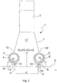
- Figures 1 and 2 show a first embodiment of the device, indicated by reference numeral 1 as a whole.
- the feeding means comprise two feeding or delivery collectors 2, 2' provided with a delivery pipe 4, 4' placed on a side of the device, respectively.
- the feeding collectors 2, 2' are provided with two respective members 14, 15, 14', 15' appropriately machined and joined so as to define respective delivery nozzles or slots 5, 5' for delivering an air jet or blade.
- An air flow enters the feeding collectors 2, 2' through the delivery pipes 4, 4', and the jets exit from the nozzles 5, 5'.
- the jets are fed by the delivery pipes 4, 4' which are engaged onto the collectors 2, 2' of larger diameter, as shown in Fig. 2 .
- the delivery pipes 4, 4' may be inserted into the collectors 2, 2', along the longitudinal extension of the device, and communicate with the latter by means of delivery equalization holes (not shown), so as to ensure feeding uniformity along the longitudinal extension of the nozzles 5, 5'.
- the jets may be fed from both sides of the device or from only one side.
- the delivery nozzles are fed from only one side.
- the configuration of the collectors 2, 2' provided on the ends 18, 18' of the bell 7 close to the feed plane of the strip, and the configuration of the corresponding nozzles 5, 5' are such that the flat air jets emitted by said nozzles are appropriately angled with respect to the surface of the strip and oriented in a reciprocally opposite sense.
- the jet of the first nozzle 5' produces a concentrated viscous shearing action on the strip being fed, by atomizing and removing the liquid film from the surface of the strip and/or by lifting and removing the solid particles existing thereon.
- the "holding jet” has a flow rate Q 1 lower than flow rate Q 2 of the "removing jet", therefore the higher shearing strength is the one produced by the jet properly named removing jet.
- the resulting jet produced by the impact of the two delivery jets i.e. the removing jet and the holding jet, is locally evacuated by the suction means in order to ensure that the atomized liquid and/or the raised particles are removed from the zone of the product being fed.
- the suction means comprise a suction hood 3 communicating with the tubular bell 7.
- the hood 3 creates a vacuum in the inner volume or collection chamber 17 of the tubular bell 7. Due to this vacuum, an air flow rate Q x is advantageously drawn from the external environment through the free section existing between the device 1 and the strip 6, thus ensuring a further tightness of the flows Q 1 and Q 2 generated within the bell 7 by means of the delivery jets.
- the distance "d" between the two nozzles 5, 5' is advantageously variable in the range from 5 to 2000 mm, preferably from 200 to 300 mm, according to some parameters such as air pressure and flow rate, impact angle of the jets on the strip surface, type of substance to be removed.
- the distance d 1 , d 2 between the nozzles 5, 5' and the strip feed plane varies from 5 to 100 mm.
- the shearing strength action of the jets on the strip may be modulated and up to three times higher than that of the jets emitted by the nozzles installed in the known devices, especially due to the close distance.
- the geometric configuration of the air jets or blades includes a nozzle opening of 1-5 mm and an impact angle of the delivery jets, i.e. an inclination angle of the nozzles with respect to the feed plane of the strip, variable in the range from 30 to 85°.
- the delivery jets form a 60° angle with respect to the strip surface; the opening of the nozzles is of 1,5 mm and the distance d 1 , d 2 of the nozzles 5, 5' from the feed plane of the strip is of 20 mm.
- the distance d 1 of the nozzle 5 may be different from the distance d 2 of the nozzle 5' from the feed plane of strip 6.
- the inclination angle ⁇ of nozzle 5 with respect to the strip feed plane may also be different from the inclination angle ⁇ of nozzle 5'.
- the distance d 1 of the delivery nozzle 5 from the feed plane of strip 6 is of about 20-30 mm, with an angle ⁇ of 45°
- the distance d 2 of the delivery nozzle 5' from said feed plane is of about 10-20 mm, with an angle ⁇ of 60 °.
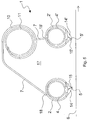
- Figures 9 and 10 show some results of the theoretical calculations which have preceded the experimental tests. In particular, these figures refer to the case with removing jet pressure of 100 mbar, holding jet pressure of 50 mbar and vacuum at the pipe of the hood of -20 mbar.
- Fig. 9 shows a pressure profile 2D on the strip, with indication of the attraction zones 23, 24 and repulsion zones 20, 21, 22 of the strip.
- the repulsion is determined by impacting the jets on the strip 6 at the zones 20 and 21 and by stopping the holding and removing jets at the zone 22; the attraction is caused by the suction, which affects the zones 23 and 24 intermediate with respect to the repulsion zones. Balancing these zones advantageously ensures the neutrality of the forces acting on the strip, i.e. the repulsion forces balance the attraction forces.
- the "reciprocal" extension of the attraction and repulsion areas depends on the geometric repulsion of the device and on the feeding and suction conditions.
- Fig. 10 is a diagram of the device in Fig. 1 with indication of the vectors of forces acting in the various attraction and repulsion zones.
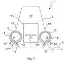
- FIG. 7 and 8 A second embodiment of the device of the invention is shown in Figures 7 and 8 .
- This embodiment comprises all components and variants thereof described for the first embodiment of the device of the invention with a main difference, as compared to the device in Fig. 1 , represented by the fact that the suction means do not include the suction hood 3 in a distal position from the strip feed plane or path, said hood communicating with the tubular bell 7 which is arranged in a position proximal to said feed plane.
- the suction means comprise two suction pipes 11', each arranged at a side end 60 of the device 1, i.e. arranged at the sides of the longitudinal feed path of the strip 6, and substantially at the feeding collectors 2, 2'.
- the suction collectors 11' laterally communicate with the inner volume 17 of the tubular bell 7, in a substantially central position with respect to the feeding collectors 2, 2', and thus also to the delivery pipes 4, 4', and can be provided on only one side or both sides of device 1.
- the suction pipes 11' at least one dedicated fan, arranged for suction, returns flow from the tubular bell 7 forming a vacuum inside the inner volume 17 thereof.
- an air flow rate Q x is advantageously returned from the external environment through the free section existing between device 1 and strip 6, thus ensuring a further tightness of the flows Q 1 and Q 2 generated within the bell 7 by means of the delivery jets.
- This resulting flow Q TOT is advantageously laterally aspirated by the two suction pipes 11', each of the two pipes 11' aspirating an air flow rate of about Q TOT /2.
- the main advantage of this embodiment of the invention is that the lateral configuration of the suction pipes 11', engaged in the collection chamber 17 substantially at the height of the feeding collectors 2, 2', prevents any attraction force from being exerted on the surface of the strip because the suction flow is split into two currents of equal flow rate, in a parallel direction with respect to the strip surface and in an opposite sense, whereby their effect is neutralized.
- the drying and cleaning device of the invention may be nearly entirely formed by pipes made of stainless steel, for example DIN 2462. However, it may also be made by using different methods and shapes without therefore departing from the scope of the invention.
- the feeding collectors 2, 2' are preferably but not necessarily circular tubes.
- the delivery collectors 4, 4' are preferably but not necessarily circular tubes.
- the suction pipes 11' are preferably but not necessary square-section tubes, e.g. rectangular tubes ( Fig. 7 ).
- the nozzles or slots 5, 5' may have a longitudinal extension equal to that of the feeding collectors 2, 2' or a plurality of nozzles of smaller extension along a same feeding collector may be provided.
- the nozzles 5, 5' may be either parallel to one another or arranged along reciprocally incident lines.
- a single side suction pipe 11' may be provided, applied to the side end 60 of the device 1 to which a greater volume of tubular bell corresponds.
- At least one nozzle 5, in section along a plane parallel to the strip feed plane, has a broken-line shape comprising three parts: a central part of the broken line is parallel to the other rectilinear nozzle 5', while the two side parts of the broken line are either converging or diverging with respect to the other rectilinear nozzle 5'.
- the pneumatic dimensioning of the device includes using fans and feeding air at ambient temperature.
- the pressures for feeding air to the nozzles 5, 5' are advantageously in the range from 50 to 400 mbar.
- a small- or medium-sized delivery fan is able to ensure this lift.
- the suction vacuums or overpressures which determine the suction flow rate may vary from 0 to 600 mbar, preferably between 250 and 500 mbar, and between 0 and 100 mbar, respectively.
- the suction pressure in the pipes 11' is produced by means of a medium-sized extraction fan.
- the extraction fan is connected to both sides, and thus to all pipes 11', while during the step of feeding, the delivery fan is connected at only one side to the pipe 4, 4'.
- the rectilinear-shaped drying device defines a longitudinal axis and may be installed with said longitudinal axis preferably but not necessarily orthogonal to the feed direction of the strip 6.
- the device may advantageously be connected both for delivery and for suction to higher efficiency aeraulic machines, such as compressors, without any restriction.
- the delivery pressures may be in the range from 0,4 to 2 bars and more, the suction vacuums may reach 0,8 bar.
- the opening of nozzle 5 may also be larger, up to a value of 10 mm.
- the device may be mounted so as to be fixed with respect to the strip feed path or may be provided with degrees of freedom. In this second case, it may be spaced from said path to allow specific steps of the process, such as for example the insertion of the first length of the strip, or may be continuously adjusted, for example to manage the distance of the device from the strip or to track the exact positioning of the strip by means of transversal movements.
- the device being either fixed or provided with degrees of freedom, may be advantageously used also for drying and cleaning static flat surfaces of metal products, such as strips, sheets, blooms and billets, the device being motorized and being possible to establish a relative motion with respect to said flat surfaces.
- Both feeding and suction may be connected at both ends of the device or at one end only.
- suction it is preferable to connect the extraction fan at both sides, then to all the pipes 11', but if this configuration is not feasible due to layout constraints, the device is able to ensure high performance even with the connection at only one side.
- a heater may advantageously be included between the delivery fan and the drying and cleaning device serving the function of increasing the air temperature, e.g. up to temperatures from 100 to 400°C.
- the hot air allows to engage a mechanism for evaporating the emulsion which is added to the atomization induced by the viscous shearing.
- a heater of power proportioned to the enthalpy of the air to be fed is needed in the delivery branch.
- a filter for the delivery air in order to avoid impurities from being carried through the jet onto the strip.
- a further filter may be also included on the suction system of the device, which filter removes the emulsion or dust from the aspirated air flow rate and thus prevents the introduction thereof into the environment.
- the suction system may be split in two parts, with respect to the two ends of the device, by means of an appropriate set of valves controlled by the corresponding pressure transducers. Adjusting the device may globally allow to control and minimize the involved powers and flow rates depending on the real conditions of the strip, considering the degree of contamination by emulsion, the speed, etc.
- the device of the invention may be installed either at only one side of the strip, for example on the upper side, or on both sides.
- the two devices may either be placed symmetrically with respect to the strip, or staggered or arranged at different distances from the strip. If the drying process occurs on different strip widths, the width of the device may advantageously be adjusted according to the width of the strip.
- a first variant of the device of the invention may be provided as split along the rectilinear extension into compartments on the feeding section and/or on that of suction, with the possibility of progressively activating external sections in parallel and proportionally to the width of the strip.
- a second variant provides, instead, for the device being adapted for the lateral insertion of movable plates capable of simulating the presence of a wider strip.
- An advantageous installation variant in particular for the first embodiment of the device of the invention, includes the positioning of the device(s) of the invention close to a means constraining the mobility of the strip, e.g. a roller about which the strip is slightly wound.
- This advantageous configuration allows possible vibrations triggered by the control of the strip traction and winding and/or by the instability of the air flows in each drying device, due for example to the even minimal operation instabilities of the delivery and suction fans, to have a minimum amplitude, limited by the closeness of the mechanical constraint.
- This optimal installation minimizes the possibility of the strip to start vibrating under the effect of the attractive force of the suction system, due to the high vacuum which is established within the external tubular bell 7.
- a high vacuum could indeed determine an attraction of the strip of intensity up to 100 kgf and over. For small thicknesses of the strip and/or low pulling forces applied to the strip, the strip could come in contact with the device, especially if the latter is very close.
- this problem may be considerably limited if the device of the invention is arranged only on one side of the strip, as the cleaning action mainly concerns the upper part of the strip.
- the cleaning action mainly concerns the upper part of the strip.
- This detailed description relates, by way of example, to the removal of liquid or solid particles from the surface of a strip.
- the device of the invention may however be used, as previously mentioned, for removing a liquid or solid particles from at least one flat surface of different metal products, such as sheets, blooms or billets.
Landscapes
- Engineering & Computer Science (AREA)
- Mechanical Engineering (AREA)
- Cleaning In General (AREA)
- Physical Or Chemical Processes And Apparatus (AREA)
- Manufacturing Of Printed Wiring (AREA)
- Powder Metallurgy (AREA)
- Drying Of Solid Materials (AREA)
Claims (6)
- Vorrichtung (1) zum Entfernen einer Flüssigkeit oder fester Teilchen von einer flachen Oberfläche eines Metall-Produktes (6), wobei die Vorrichtung und die flache Oberfläche dafür angepasst sind, sich in einer relativen Bewegung entlang eines Längs-Weges zu bewegen, wobei die Vorrichtung umfasst:- erste und zweite Zuführ-Einrichtungen (2', 2) zum Zuführen von Gas-Strahlströmen entlang der Breite des Längswegs, angeordnet in einer Position proximal zu dem Längs-Weg und zu der Oberfläche des Metall-Produkts (6);- ein Gehäuse (7), enthaltend eine Sammel-Kammer (17) zum Sammeln von Flüssigkeit oder festen Teilchen, die von der flachen Oberfläche des Metall-Produktes mittels der Gas-Strahlströme entfernt werden;- worin die ersten Zufuhr-Einrichtungen (2') so konfiguriert sind, dass sie einen ersten Gasstrom (Q1) mit einer Vektor-Komponente in einer Richtung gegenläufig zu der Richtung der relativen Bewegung erzeugen, und die zweiten Zuführ-Einrichtungen (2) so konfiguriert sind, dass sie einen zweiten Gasstrom (Q2) mit einer Vektor-Komponente in derselben Richtung wie die Richtung der relativen Bewegung erzeugen, um den ersten Strom innerhalb der Sammel-Kammer (17) auszurichten, worin Saug-Einrichtungen (11') vorgesehen sind, die an der Seite des Längs-Weges und im Wesentlichen an den ersten und zweiten Zuführ-Einrichtungen (2', 2) angeordnet sind, wobei die Sammel-Kammer (17) zentral zwischen den beiden Zuführ-Einrichtungen (2', 2) ist und an wenigstens einem Seiten-Ende (60) der Vorrichtung (1) mit den Saug-Einrichtungen (11') in Verbindung steht, wobei die ersten und zweiten Ströme, die im Betrieb auf der flachen Oberfläche des Metall-Produkts von den Strahlströmen produziert werden, und ein dritter Strom (Qx), der von der Außenumgebung durch einen freien Abschnitt angesaugt wird, der zwischen der Vorrichtung (1) und der flachen Oberfläche des Metall-Produkts (6) existiert, innerhalb der Sammel-Kammer (17) umgelenkt werden, so dass sich der resultierende Strom (Qtot) weg von der flachen Oberfläche des Metall-Produkts (6) bewegt, wobei die ersten und zweiten Zuführ-Einrichtungen (2', 2) an Enden (18, 18') des Gehäuses (7) vorgesehen sind, dadurch gekennzeichnet, dass erste und zweite Gas-Strahlstrom-Zuführ-Einrichtungen jeweils einen ersten schlauchförmigen Sammler umfassen, der versehen ist mit einer entsprechenden Injektionsdüse (5', 5) des Strahlstroms entlang seiner Längs-Ausdehnung, wobei jede Injektionsdüse (5', 5) um einen vorbestimmten Abstand (d2, d1), der im Bereich von 5 mm bis 100 mm liegt, von dem Weg beabstandet ist, wobei die Entfernung "d" zwischen den beiden Injektionsdüsen (5, 5') im Bereich von 5 bis 2000 mm eingeschlossen ist, die Öffnung der Düsen (5, 5') im Bereich von 1 bis 10 mm eingeschlossen ist und der Neigungswinkel (α, β) der Düsen (5, 5') in Bezug auf die Zuführ-Ebene des Streifens im Bereich von 30° bis 85° eingeschlossen ist.
- Vorrichtung nach Anspruch 1, wobei die Saug-Einrichtungen zwei Saug-Rohre (11') umfassen, jedes angeordnet an einem Seiten-Ende (60) der Vorrichtung (1) seitlich in Kontakt stehend mit der Sammel-Kammer (17) in einer zentralen Position in Bezug auf die Zuführ-Einrichtungen (2, 2').
- Vorrichtung nach Anspruch 2, wobei die Öffnung der Düsen (5, 5') 1,5 mm beträgt und der Neigungswinkel (α, β) 60° beträgt.
- Vorrichtung nach Anspruch 3, wobei der Neigungswinkel (β) einer ersten Düse (5') entweder gleich ist zu oder verschieden ist von dem Neigungswinkel (α) einer zweiten Düse (5).
- Vorrichtung nach irgendeinem der Ansprüche 1 bis 4, wobei jeder erste schlauchförmige Sammler versehen ist mit einem Ableit-Rohr (4, 4'), das an wenigstens einer Seite der Vorrichtung platziert ist und das entweder im Eingriff mit dem ersten Sammler ist, der einen Durchmesser aufweist, der größer ist als das Ableit-Rohr, oder in den ersten Sammler entlang der Längsausdehnung der Vorrichtung eingesetzt ist und in Verbindung mit letzterem mittels Löchern zum Ausgleichen der Durchflussgeschwindigkeit steht.
- Verfahren zum Entfernen einer Flüssigkeit oder fester Teilchen von einer flachen Oberfläche eines Metall-Produkts mittels einer Vorrichtung nach Anspruch 1, wobei sich die Vorrichtung und die flache Oberfläche gegeneinander in einer relativen Bewegung entlang einem Längs-Weg bewegen, wobei das Verfahren die folgenden Schritte umfasst:- Zuführen eines ersten Gas-Stroms, der eine Vektor-Komponente in derselben Richtung wie die Richtung der relativen Bewegung aufweist, mittels erster Zuführ-Einrichtungen (2'), die in einer Position proximal zu dem Längs-Weg platziert sind;- Zuführen eines zweiten Gas-Stroms, der eine Vektor-Komponente in der Richtung gegenläufig zu der Richtung der relativen Bewegung aufweist, mittels zweiter Zuführ-Einrichtungen (2), die in einer Position proximal zu dem Längs-Weg platziert sind, so dass der erste Strom innerhalb eines Volumens (17) zwischen den ersten und den zweiten Zuführ-Einrichtungen (2', 2) enthalten ist;- wobei vorgesehen ist der weitere Schritt, dass man in einem resultierenden Strom (Qtot) der Vektor-Komponenten des ersten und des zweiten Stroms (Q1, Q2) mittels der Saug-Einrichtungen (11'), die an der Seite des Längs-Wegs und im Wesentlichen an den ersten und zweiten Zuführ-Einrichtungen (2', 2) angeordnet sind, und von der flachen Oberfläche des Metall-Produktes (6) saugt, wodurch der erste und der zweite Gas-Strom (Q1, Q2) und ein dritter Strom (Qx), der von der Außenumgebung durch einen freien Abschnitt angesaugt wird, der zwischen der Vorrichtung (1) und der flachen Oberfläche des Metall-Produkts (6) existiert, innerhalb der Sammel-Kammer (17) umgelenkt werden, so dass sich der resultierende Strom (Qtot) weg von der flachen Oberfläche des Metall-Produkts (6) bewegt.
Applications Claiming Priority (2)
| Application Number | Priority Date | Filing Date | Title |
|---|---|---|---|
| IT001162A ITMI20081162A1 (it) | 2008-06-26 | 2008-06-26 | Dispositivo per la rimozione di liquido o particelle solide da una superficie piana di un prodotto metallico |
| PCT/IB2009/052712 WO2009156956A2 (en) | 2008-06-26 | 2009-06-24 | Device for removing a liquid or solid particles from a flat surface of a metal product |
Publications (2)
| Publication Number | Publication Date |
|---|---|
| EP2323780A2 EP2323780A2 (de) | 2011-05-25 |
| EP2323780B1 true EP2323780B1 (de) | 2016-01-27 |
Family
ID=40301862
Family Applications (1)
| Application Number | Title | Priority Date | Filing Date |
|---|---|---|---|
| EP09769764.3A Active EP2323780B1 (de) | 2008-06-26 | 2009-06-24 | Vorrichtung zum entfernen einer flüssigkeit oder fester partikel von einer flachen fläche eines metallprodukts |
Country Status (6)
| Country | Link |
|---|---|
| EP (1) | EP2323780B1 (de) |
| CN (1) | CN102083561B (de) |
| BR (1) | BRPI0914848A2 (de) |
| ES (1) | ES2568925T3 (de) |
| IT (1) | ITMI20081162A1 (de) |
| WO (1) | WO2009156956A2 (de) |
Families Citing this family (5)
| Publication number | Priority date | Publication date | Assignee | Title |
|---|---|---|---|---|
| DE102011001639A1 (de) * | 2011-03-29 | 2012-10-04 | Turbofilter Gmbh | Vorrichtung zur Oberflächenreinigung bewegter Materialbahnen |
| BE1025125B1 (fr) | 2017-09-04 | 2018-10-31 | Centre de Recherches Métallurgiques asbl-Centrum voor Research in de Metallurgie vzw | Essuyeur sans contact et installation industrielle comportant un tel essuyeur |
| IT202000012205A1 (it) | 2020-05-25 | 2021-11-25 | F M Srl | Processo e impianto di separazione di materiale sospeso |
| IT202000012211A1 (it) * | 2020-05-25 | 2021-11-25 | F M Srl | Sistema di captazione e processo di produzione di tale sistema di captazione |
| CN114769337A (zh) * | 2022-05-20 | 2022-07-22 | 陈洋 | 一种铜带加工设备 |
Family Cites Families (5)
| Publication number | Priority date | Publication date | Assignee | Title |
|---|---|---|---|---|
| DE19519544C2 (de) * | 1995-05-27 | 1999-08-19 | Sundwig Gmbh | Vorrichtung zum Entfernen von Flüssigkeit von der Oberfläche eines Bandes |
| US6134811A (en) * | 1996-06-24 | 2000-10-24 | Sundwig Gmbh | Device for removing liquid from the surface of a band |
| US20050126605A1 (en) * | 2003-12-15 | 2005-06-16 | Coreflow Scientific Solutions Ltd. | Apparatus and method for cleaning surfaces |
| US7931755B2 (en) * | 2003-12-19 | 2011-04-26 | Mitsuboshi Diamond Industrial Co., Ltd | Method for removing deposit from substrate and method for drying substrate, as well as apparatus for removing deposit from substrate and apparatus for drying substrate using these methods |
| ITMI20061678A1 (it) * | 2006-09-04 | 2008-03-05 | Danieli & C Officine Meccaniche Spa | Dispositivo di asciugatura nastri |
-
2008
- 2008-06-26 IT IT001162A patent/ITMI20081162A1/it unknown
-
2009
- 2009-06-24 BR BRPI0914848A patent/BRPI0914848A2/pt not_active IP Right Cessation
- 2009-06-24 WO PCT/IB2009/052712 patent/WO2009156956A2/en not_active Ceased
- 2009-06-24 ES ES09769764.3T patent/ES2568925T3/es active Active
- 2009-06-24 EP EP09769764.3A patent/EP2323780B1/de active Active
- 2009-06-24 CN CN200980124678.8A patent/CN102083561B/zh active Active
Also Published As
| Publication number | Publication date |
|---|---|
| ITMI20081162A1 (it) | 2009-12-27 |
| BRPI0914848A2 (pt) | 2019-09-24 |
| WO2009156956A9 (en) | 2010-06-03 |
| EP2323780A2 (de) | 2011-05-25 |
| WO2009156956A2 (en) | 2009-12-30 |
| CN102083561A (zh) | 2011-06-01 |
| WO2009156956A3 (en) | 2010-02-18 |
| CN102083561B (zh) | 2015-03-25 |
| ES2568925T3 (es) | 2016-05-05 |
Similar Documents
| Publication | Publication Date | Title |
|---|---|---|
| EP2323780B1 (de) | Vorrichtung zum entfernen einer flüssigkeit oder fester partikel von einer flachen fläche eines metallprodukts | |
| DE102015218650B3 (de) | Vorrichtung zum Schneiden von Blechplatinen aus einem Blechband | |
| EP2064504B1 (de) | Vorrichtung zum entfernen einer flüssigkeit oder von festen teilchen von einem flachen metallprodukt | |
| DE102009015206B4 (de) | Verfahren und Vorrichtung zum Abblasen von Walzband mittels Luft oder gasförmiger Medien auf der Bandauslaufseite von Walzwerken zum Entfernen von an dem Walzband anhaftendem Walzöl oder anderen flüssigen Betriebsmedien | |
| EP1474253B1 (de) | Vorrichtung zum trockenhalten von kaltband im auslauf von bandwalzanlagen | |
| JP3356283B2 (ja) | 連続移動する金属ストリップの温度制御のために液体冷媒を適用および除去する方法および装置 | |
| KR101689155B1 (ko) | 압연 스톡 냉각 장치 | |
| US5398372A (en) | Liquid edge bead removal device | |
| EP1979103A1 (de) | Bandreinigungsvorrichtung | |
| US5758530A (en) | Hot rolling mill | |
| WO2015139347A1 (zh) | 一种高效除磷方法及其装置 | |
| EP0440971B1 (de) | Vorrichtung zur Bahnlaufsteuerung | |
| JP2001353515A (ja) | 高温鋼板の水切り方法及びその装置 | |
| CN202725622U (zh) | 一种冷轧机 | |
| RU2358818C1 (ru) | Прокатная установка | |
| KR100613262B1 (ko) | 압연 선재 이물질 제거장치 | |
| JP2005279786A (ja) | 線材表面研削装置 | |
| EP0696647A1 (de) | Inline-Beschichtung von Stahlrohren | |
| JPS5916617A (ja) | 厚鋼板のオンライン冷却装置 | |
| JP3360891B2 (ja) | ストリップ位置調整装置 | |
| KR102721136B1 (ko) | 전극 제조 장치 및 전극 제조 장치의 작동 방법 | |
| CN101829683B (zh) | 冷凝水阻断方法 | |
| KR20030031270A (ko) | 고압 냉각수의 차단장치 | |
| KR820001151B1 (ko) | 이동금속 스트립(strip)의 화염 절단 장치 | |
| JPS61153235A (ja) | 厚鋼板のオンライン冷却方法 |
Legal Events
| Date | Code | Title | Description |
|---|---|---|---|
| PUAI | Public reference made under article 153(3) epc to a published international application that has entered the european phase |
Free format text: ORIGINAL CODE: 0009012 |
|
| 17P | Request for examination filed |
Effective date: 20110125 |
|
| AK | Designated contracting states |
Kind code of ref document: A2 Designated state(s): AT BE BG CH CY CZ DE DK EE ES FI FR GB GR HR HU IE IS IT LI LT LU LV MC MK MT NL NO PL PT RO SE SI SK TR |
|
| AX | Request for extension of the european patent |
Extension state: AL BA RS |
|
| DAX | Request for extension of the european patent (deleted) | ||
| 17Q | First examination report despatched |
Effective date: 20130109 |
|
| GRAP | Despatch of communication of intention to grant a patent |
Free format text: ORIGINAL CODE: EPIDOSNIGR1 |
|
| INTG | Intention to grant announced |
Effective date: 20150728 |
|
| GRAS | Grant fee paid |
Free format text: ORIGINAL CODE: EPIDOSNIGR3 |
|
| GRAA | (expected) grant |
Free format text: ORIGINAL CODE: 0009210 |
|
| AK | Designated contracting states |
Kind code of ref document: B1 Designated state(s): AT BE BG CH CY CZ DE DK EE ES FI FR GB GR HR HU IE IS IT LI LT LU LV MC MK MT NL NO PL PT RO SE SI SK TR |
|
| REG | Reference to a national code |
Ref country code: GB Ref legal event code: FG4D |
|
| REG | Reference to a national code |
Ref country code: CH Ref legal event code: EP |
|
| REG | Reference to a national code |
Ref country code: AT Ref legal event code: REF Ref document number: 772452 Country of ref document: AT Kind code of ref document: T Effective date: 20160215 |
|
| REG | Reference to a national code |
Ref country code: IE Ref legal event code: FG4D |
|
| REG | Reference to a national code |
Ref country code: DE Ref legal event code: R096 Ref document number: 602009036049 Country of ref document: DE |
|
| REG | Reference to a national code |
Ref country code: ES Ref legal event code: FG2A Ref document number: 2568925 Country of ref document: ES Kind code of ref document: T3 Effective date: 20160505 |
|
| REG | Reference to a national code |
Ref country code: LT Ref legal event code: MG4D |
|
| REG | Reference to a national code |
Ref country code: FR Ref legal event code: PLFP Year of fee payment: 8 |
|
| REG | Reference to a national code |
Ref country code: NL Ref legal event code: MP Effective date: 20160127 |
|
| PG25 | Lapsed in a contracting state [announced via postgrant information from national office to epo] |
Ref country code: NL Free format text: LAPSE BECAUSE OF FAILURE TO SUBMIT A TRANSLATION OF THE DESCRIPTION OR TO PAY THE FEE WITHIN THE PRESCRIBED TIME-LIMIT Effective date: 20160127 |
|
| PG25 | Lapsed in a contracting state [announced via postgrant information from national office to epo] |
Ref country code: NO Free format text: LAPSE BECAUSE OF FAILURE TO SUBMIT A TRANSLATION OF THE DESCRIPTION OR TO PAY THE FEE WITHIN THE PRESCRIBED TIME-LIMIT Effective date: 20160427 Ref country code: GR Free format text: LAPSE BECAUSE OF FAILURE TO SUBMIT A TRANSLATION OF THE DESCRIPTION OR TO PAY THE FEE WITHIN THE PRESCRIBED TIME-LIMIT Effective date: 20160428 Ref country code: HR Free format text: LAPSE BECAUSE OF FAILURE TO SUBMIT A TRANSLATION OF THE DESCRIPTION OR TO PAY THE FEE WITHIN THE PRESCRIBED TIME-LIMIT Effective date: 20160127 Ref country code: FI Free format text: LAPSE BECAUSE OF FAILURE TO SUBMIT A TRANSLATION OF THE DESCRIPTION OR TO PAY THE FEE WITHIN THE PRESCRIBED TIME-LIMIT Effective date: 20160127 |
|
| PG25 | Lapsed in a contracting state [announced via postgrant information from national office to epo] |
Ref country code: SE Free format text: LAPSE BECAUSE OF FAILURE TO SUBMIT A TRANSLATION OF THE DESCRIPTION OR TO PAY THE FEE WITHIN THE PRESCRIBED TIME-LIMIT Effective date: 20160127 Ref country code: LV Free format text: LAPSE BECAUSE OF FAILURE TO SUBMIT A TRANSLATION OF THE DESCRIPTION OR TO PAY THE FEE WITHIN THE PRESCRIBED TIME-LIMIT Effective date: 20160127 Ref country code: IS Free format text: LAPSE BECAUSE OF FAILURE TO SUBMIT A TRANSLATION OF THE DESCRIPTION OR TO PAY THE FEE WITHIN THE PRESCRIBED TIME-LIMIT Effective date: 20160527 Ref country code: PL Free format text: LAPSE BECAUSE OF FAILURE TO SUBMIT A TRANSLATION OF THE DESCRIPTION OR TO PAY THE FEE WITHIN THE PRESCRIBED TIME-LIMIT Effective date: 20160127 Ref country code: PT Free format text: LAPSE BECAUSE OF FAILURE TO SUBMIT A TRANSLATION OF THE DESCRIPTION OR TO PAY THE FEE WITHIN THE PRESCRIBED TIME-LIMIT Effective date: 20160527 Ref country code: LT Free format text: LAPSE BECAUSE OF FAILURE TO SUBMIT A TRANSLATION OF THE DESCRIPTION OR TO PAY THE FEE WITHIN THE PRESCRIBED TIME-LIMIT Effective date: 20160127 |
|
| REG | Reference to a national code |
Ref country code: DE Ref legal event code: R097 Ref document number: 602009036049 Country of ref document: DE |
|
| PG25 | Lapsed in a contracting state [announced via postgrant information from national office to epo] |
Ref country code: EE Free format text: LAPSE BECAUSE OF FAILURE TO SUBMIT A TRANSLATION OF THE DESCRIPTION OR TO PAY THE FEE WITHIN THE PRESCRIBED TIME-LIMIT Effective date: 20160127 Ref country code: DK Free format text: LAPSE BECAUSE OF FAILURE TO SUBMIT A TRANSLATION OF THE DESCRIPTION OR TO PAY THE FEE WITHIN THE PRESCRIBED TIME-LIMIT Effective date: 20160127 |
|
| PG25 | Lapsed in a contracting state [announced via postgrant information from national office to epo] |
Ref country code: CZ Free format text: LAPSE BECAUSE OF FAILURE TO SUBMIT A TRANSLATION OF THE DESCRIPTION OR TO PAY THE FEE WITHIN THE PRESCRIBED TIME-LIMIT Effective date: 20160127 Ref country code: RO Free format text: LAPSE BECAUSE OF FAILURE TO SUBMIT A TRANSLATION OF THE DESCRIPTION OR TO PAY THE FEE WITHIN THE PRESCRIBED TIME-LIMIT Effective date: 20160127 Ref country code: SK Free format text: LAPSE BECAUSE OF FAILURE TO SUBMIT A TRANSLATION OF THE DESCRIPTION OR TO PAY THE FEE WITHIN THE PRESCRIBED TIME-LIMIT Effective date: 20160127 |
|
| PLBE | No opposition filed within time limit |
Free format text: ORIGINAL CODE: 0009261 |
|
| STAA | Information on the status of an ep patent application or granted ep patent |
Free format text: STATUS: NO OPPOSITION FILED WITHIN TIME LIMIT |
|
| PG25 | Lapsed in a contracting state [announced via postgrant information from national office to epo] |
Ref country code: BE Free format text: LAPSE BECAUSE OF FAILURE TO SUBMIT A TRANSLATION OF THE DESCRIPTION OR TO PAY THE FEE WITHIN THE PRESCRIBED TIME-LIMIT Effective date: 20160127 |
|
| 26N | No opposition filed |
Effective date: 20161028 |
|
| PG25 | Lapsed in a contracting state [announced via postgrant information from national office to epo] |
Ref country code: MC Free format text: LAPSE BECAUSE OF FAILURE TO SUBMIT A TRANSLATION OF THE DESCRIPTION OR TO PAY THE FEE WITHIN THE PRESCRIBED TIME-LIMIT Effective date: 20160127 |
|
| REG | Reference to a national code |
Ref country code: CH Ref legal event code: PL |
|
| PG25 | Lapsed in a contracting state [announced via postgrant information from national office to epo] |
Ref country code: BG Free format text: LAPSE BECAUSE OF FAILURE TO SUBMIT A TRANSLATION OF THE DESCRIPTION OR TO PAY THE FEE WITHIN THE PRESCRIBED TIME-LIMIT Effective date: 20160427 Ref country code: SI Free format text: LAPSE BECAUSE OF FAILURE TO SUBMIT A TRANSLATION OF THE DESCRIPTION OR TO PAY THE FEE WITHIN THE PRESCRIBED TIME-LIMIT Effective date: 20160127 |
|
| REG | Reference to a national code |
Ref country code: IE Ref legal event code: MM4A |
|
| PG25 | Lapsed in a contracting state [announced via postgrant information from national office to epo] |
Ref country code: LI Free format text: LAPSE BECAUSE OF NON-PAYMENT OF DUE FEES Effective date: 20160630 Ref country code: CH Free format text: LAPSE BECAUSE OF NON-PAYMENT OF DUE FEES Effective date: 20160630 |
|
| REG | Reference to a national code |
Ref country code: FR Ref legal event code: PLFP Year of fee payment: 9 |
|
| PG25 | Lapsed in a contracting state [announced via postgrant information from national office to epo] |
Ref country code: IE Free format text: LAPSE BECAUSE OF NON-PAYMENT OF DUE FEES Effective date: 20160624 |
|
| PGFP | Annual fee paid to national office [announced via postgrant information from national office to epo] |
Ref country code: GB Payment date: 20170526 Year of fee payment: 9 Ref country code: FR Payment date: 20170523 Year of fee payment: 9 |
|
| PGFP | Annual fee paid to national office [announced via postgrant information from national office to epo] |
Ref country code: ES Payment date: 20170703 Year of fee payment: 9 |
|
| PG25 | Lapsed in a contracting state [announced via postgrant information from national office to epo] |
Ref country code: HU Free format text: LAPSE BECAUSE OF FAILURE TO SUBMIT A TRANSLATION OF THE DESCRIPTION OR TO PAY THE FEE WITHIN THE PRESCRIBED TIME-LIMIT; INVALID AB INITIO Effective date: 20090624 Ref country code: CY Free format text: LAPSE BECAUSE OF FAILURE TO SUBMIT A TRANSLATION OF THE DESCRIPTION OR TO PAY THE FEE WITHIN THE PRESCRIBED TIME-LIMIT Effective date: 20160127 |
|
| PG25 | Lapsed in a contracting state [announced via postgrant information from national office to epo] |
Ref country code: LU Free format text: LAPSE BECAUSE OF NON-PAYMENT OF DUE FEES Effective date: 20160624 Ref country code: TR Free format text: LAPSE BECAUSE OF FAILURE TO SUBMIT A TRANSLATION OF THE DESCRIPTION OR TO PAY THE FEE WITHIN THE PRESCRIBED TIME-LIMIT Effective date: 20160127 Ref country code: MK Free format text: LAPSE BECAUSE OF FAILURE TO SUBMIT A TRANSLATION OF THE DESCRIPTION OR TO PAY THE FEE WITHIN THE PRESCRIBED TIME-LIMIT Effective date: 20160127 Ref country code: MT Free format text: LAPSE BECAUSE OF NON-PAYMENT OF DUE FEES Effective date: 20160630 |
|
| REG | Reference to a national code |
Ref country code: AT Ref legal event code: UEP Ref document number: 772452 Country of ref document: AT Kind code of ref document: T Effective date: 20160127 |
|
| GBPC | Gb: european patent ceased through non-payment of renewal fee |
Effective date: 20180624 |
|
| PG25 | Lapsed in a contracting state [announced via postgrant information from national office to epo] |
Ref country code: FR Free format text: LAPSE BECAUSE OF NON-PAYMENT OF DUE FEES Effective date: 20180630 Ref country code: GB Free format text: LAPSE BECAUSE OF NON-PAYMENT OF DUE FEES Effective date: 20180624 |
|
| REG | Reference to a national code |
Ref country code: ES Ref legal event code: FD2A Effective date: 20190916 |
|
| PG25 | Lapsed in a contracting state [announced via postgrant information from national office to epo] |
Ref country code: ES Free format text: LAPSE BECAUSE OF NON-PAYMENT OF DUE FEES Effective date: 20180625 |
|
| PGFP | Annual fee paid to national office [announced via postgrant information from national office to epo] |
Ref country code: AT Payment date: 20200520 Year of fee payment: 12 |
|
| REG | Reference to a national code |
Ref country code: AT Ref legal event code: MM01 Ref document number: 772452 Country of ref document: AT Kind code of ref document: T Effective date: 20210624 |
|
| PG25 | Lapsed in a contracting state [announced via postgrant information from national office to epo] |
Ref country code: AT Free format text: LAPSE BECAUSE OF NON-PAYMENT OF DUE FEES Effective date: 20210624 |
|
| P01 | Opt-out of the competence of the unified patent court (upc) registered |
Effective date: 20230511 |
|
| PGFP | Annual fee paid to national office [announced via postgrant information from national office to epo] |
Ref country code: DE Payment date: 20250627 Year of fee payment: 17 |
|
| PGFP | Annual fee paid to national office [announced via postgrant information from national office to epo] |
Ref country code: IT Payment date: 20250619 Year of fee payment: 17 |