EP2323945B1 - Procédé et système de retrait de bouchon de liège - Google Patents
Procédé et système de retrait de bouchon de liège Download PDFInfo
- Publication number
- EP2323945B1 EP2323945B1 EP09806519.6A EP09806519A EP2323945B1 EP 2323945 B1 EP2323945 B1 EP 2323945B1 EP 09806519 A EP09806519 A EP 09806519A EP 2323945 B1 EP2323945 B1 EP 2323945B1
- Authority
- EP
- European Patent Office
- Prior art keywords
- cover
- gas
- gas cell
- sealing member
- cell
- Prior art date
- Legal status (The legal status is an assumption and is not a legal conclusion. Google has not performed a legal analysis and makes no representation as to the accuracy of the status listed.)
- Not-in-force
Links
- 239000007799 cork Substances 0.000 title claims description 25
- 238000000034 method Methods 0.000 title claims description 23
- 239000007789 gas Substances 0.000 claims description 132
- 230000007246 mechanism Effects 0.000 claims description 36
- 238000007789 sealing Methods 0.000 claims description 30
- 230000004913 activation Effects 0.000 claims description 12
- 230000003213 activating effect Effects 0.000 claims description 7
- IJGRMHOSHXDMSA-UHFFFAOYSA-N Atomic nitrogen Chemical compound N#N IJGRMHOSHXDMSA-UHFFFAOYSA-N 0.000 claims description 6
- 230000000149 penetrating effect Effects 0.000 claims description 6
- 229920000642 polymer Polymers 0.000 claims description 4
- 208000027418 Wounds and injury Diseases 0.000 claims description 3
- 239000003570 air Substances 0.000 claims description 3
- 230000006378 damage Effects 0.000 claims description 3
- 239000001307 helium Substances 0.000 claims description 3
- 229910052734 helium Inorganic materials 0.000 claims description 3
- SWQJXJOGLNCZEY-UHFFFAOYSA-N helium atom Chemical compound [He] SWQJXJOGLNCZEY-UHFFFAOYSA-N 0.000 claims description 3
- 208000014674 injury Diseases 0.000 claims description 3
- 229910052757 nitrogen Inorganic materials 0.000 claims description 3
- 229910000831 Steel Inorganic materials 0.000 claims description 2
- 229910052782 aluminium Inorganic materials 0.000 claims description 2
- XAGFODPZIPBFFR-UHFFFAOYSA-N aluminium Chemical compound [Al] XAGFODPZIPBFFR-UHFFFAOYSA-N 0.000 claims description 2
- 239000000123 paper Substances 0.000 claims description 2
- 239000010959 steel Substances 0.000 claims description 2
- 239000002023 wood Substances 0.000 claims description 2
- 239000000463 material Substances 0.000 claims 4
- 235000014101 wine Nutrition 0.000 description 8
- 238000013459 approach Methods 0.000 description 3
- 238000012986 modification Methods 0.000 description 2
- 230000004048 modification Effects 0.000 description 2
- 238000010276 construction Methods 0.000 description 1
- 239000011521 glass Substances 0.000 description 1
- 229910052751 metal Inorganic materials 0.000 description 1
- 239000002184 metal Substances 0.000 description 1
- 230000008520 organization Effects 0.000 description 1
- 230000035515 penetration Effects 0.000 description 1
- 230000002028 premature Effects 0.000 description 1
- 230000000284 resting effect Effects 0.000 description 1
- 238000005507 spraying Methods 0.000 description 1
Images




Classifications
-
- B—PERFORMING OPERATIONS; TRANSPORTING
- B67—OPENING, CLOSING OR CLEANING BOTTLES, JARS OR SIMILAR CONTAINERS; LIQUID HANDLING
- B67B—APPLYING CLOSURE MEMBERS TO BOTTLES JARS, OR SIMILAR CONTAINERS; OPENING CLOSED CONTAINERS
- B67B7/00—Hand- or power-operated devices for opening closed containers
- B67B7/02—Hand- or power-operated devices for opening closed containers for removing stoppers
- B67B7/06—Other cork removers
- B67B7/08—Other cork removers using air or gas pressure
-
- B—PERFORMING OPERATIONS; TRANSPORTING
- B65—CONVEYING; PACKING; STORING; HANDLING THIN OR FILAMENTARY MATERIAL
- B65D—CONTAINERS FOR STORAGE OR TRANSPORT OF ARTICLES OR MATERIALS, e.g. BAGS, BARRELS, BOTTLES, BOXES, CANS, CARTONS, CRATES, DRUMS, JARS, TANKS, HOPPERS, FORWARDING CONTAINERS; ACCESSORIES, CLOSURES, OR FITTINGS THEREFOR; PACKAGING ELEMENTS; PACKAGES
- B65D39/00—Closures arranged within necks or pouring openings or in discharge apertures, e.g. stoppers
- B65D39/16—Closures arranged within necks or pouring openings or in discharge apertures, e.g. stoppers with handles or other special means facilitating manual actuation
Definitions
- the invention is in the field of drink and food industries, and in special it deals with removal of corks out of wine bottles.
- the invention relates to a cover for a container according to the preamble of claim 1 and to a method according to the preamble of claim 13, as known from US 3,135,410 .
- the container is a bottle and the sealing member is a cork.
- the compressed gas has initial pressure from 1.5 to 3.0 bar, and it includes air, nitrogen, or helium.
- the cover includes safety means to prevent accidental activation of the gas channel mechanism.
- the gas channel mechanism includes an elongated duct having a sharp end, the sharp end is adapted for penetrating the sealing member upon pushing of the elongated duct towards the container.
- the portion of the sealing member penetrated by the sharp end is preferably 1-3 mm thick.
- the gas channel mechanism preferably includes means for hiding the sharp end within the sealing member while the compressed gas pushes the cover outwardly, thereby preventing injury by the sharp end of a person opening the cover.
- the elongated duct is preferably cylindrically shaped with an outside diameter from 1.0 to 2.0 mm.
- the gas cell is cylindrically shaped with an outside diameter from 8 to 12 mm.
- the sealing member is made of cork, wood, paper, polymer, or rubber.
- the gas cell is made of aluminum, steel, or polymer.
- activating includes the actions of rotating the gas cell relative to the ferrule, sliding the gas cell within the ferrule towards the container, breaking out a diaphragm sealing the gas cell, and penetrating the sealing member.
- each of the verbs "comprise”, “include” and “have”, and conjugates thereof, are used to indicate that the object or objects of the verb are not necessarily a complete listing of members, components, elements or parts of the subject or subjects of the verb.
- a cover 10 for a container 20 having internal volume 30 and an opening 40 is provided.
- the container 10 is a wine bottle 20 having a cork 50 as a sealing member for opening 40 which is disposed at the end of bottleneck 55.
- Fig. 1 illustrates the opening of bottle 10, whereas a gas jet 60 is sprayed into the internal volume 30 above wine level 70, increasing the gas pressure in volume 30. The increased pressure pushes cover 10 outwardly, either completely or at least enough to allow a user to conveniently remove cover 10 by tilting cover 10 aside.
- a rotating handle 80 which operation is explained bellow.
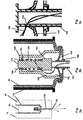
- Figs. 2 and 3 illustrate the mechanism for spraying gas jet 60 into internal volume 30.
- Fig. 2a depicts cover 10 at rest, before opening bottle 20.
- Cover 10 includes cork 50 for sealing opening 40, a gas cell 90 containing compressed gas, and a gas channel mechanism 100 for constituting a gas channel between the gas cell 90 and the internal volume 30.
- the compressed gas has an initial pressure level from 1.5 to 3.0 bar, and the gas includes air, nitrogen, or helium.
- Cylindrical gas cell 90 preferably has an outside diameter from 8 to 12 mm.
- a ferrule 110 is disposed between gas cell 90 and an interior part of cork 50, whereas gas cell 90 is slidably coupled to ferrule 110.
- the gas channel mechanism 100 includes an elongated duct 120 having a sharp end 130.
- Sharp end 130 is adapted for penetrating cork 50 upon pushing of elongated duct 120 towards container 10.
- elongated duct 120 is preferably cylindrically shaped with an outside diameter from 1.0 to 2.0 mm.
- the portion of cork 50 to be penetrated by the sharp end 130 is preferably 1-3 mm thick.
- Duct 120 has an aperture 135 on a side, for connecting the duct interior to volume 140, which is enclosed between duct 120 and an enclosing annulus 145.
- Duct 120 is attached to a cylinder 150, which in turn is attached to cylindrical post 155.
- a spring 160 is disposed on post 155, supported by cylinder 150 on one end and limited by an housing 165 on the other end.
- a diaphragm 170 seals a bore 175 in housing 165, and a thick elastic ring 180 encircles duct 120 outside housing 165.
- activating the gas channel mechanism is made by slidably pushing gas cell 90 inside ferrule 110 towards bottle 20.
- sharp edge 130 approaches the cork, there is some resistance to penetration and the end of post 155 breaks diaphragm 170. Consequently, the compressed gas residing in gas cell 90 expands into volume 185.
- the movement of post 155, attached cylinder 150 and duct 120 towards the interior of gas cell 90 slides annulus 145 relative to duct 120 and exposes aperture 135 to volume 185. Consequently, the compressed gas flows into duct 120, as exemplified by gas flow line 190.
- Bottle 20 may be opened either by total removal of cover 10 out of opening 40 by the pressurized gas, or by enabling the user to complete the cover removal by tilting the cover aside.
- Gas channel mechanism 100 preferably includes means for hiding sharp end 130 while the compressed gas pushes cork 50 outwardly, thereby preventing injury by sharp end 130 of a person opening cover 10.
- Thick elastic ring 180 of Figs 2 and 3 serves as an exemplary hiding means. While pushing gas cell 90 towards bottle 20, thick elastic ring 180 is pressed against cork 50 and becomes somewhat thinner. As pushing gas cell 90 stops and cover 10 gets out by the compressed gas, ring 180 expands enough to draw duct 120 into gas cell 90, hiding sharp end 130 inside cork 50.
- Method 200 includes the step 210 of assembling a cover 10, and the step 220 of installing cover 10 on opening 40 for sealing.
- Cover 10 includes a sealing member 50 adapted for sealing the opening 40, a gas cell 90 containing-compressed gas, and a gas channel mechanism 100 adapted for constituting a gas channel between gas cell 90 and internal volume 30.
- method 200 also includes the step 230 of activating gas channel mechanism 100 to constitute a gas channel between gas cell 90 and internal volume 30.
- cover 10 includes safety means to prevent accidental activation of the gas channel mechanism 100, as shown in Figs 5 and 6 .
- Fig. 5a is an exploded view of gas cell 90 and gas channel mechanism 100.
- housing 165 is screwed onto gas cell 90.
- Two pins 250 are disposed on opposing sides of gas cell 90 close to the end receiving gas channel mechanism 110, and a slit 260 is made on the end of cell 90 opposite to the gas channel mechanism 100.
- Fig. 5b is an exploded view of ferrule 110 and gas cell 90.
- Ferrule 110 has two L-shaped slots on opposing sides close to the end of gas cell 90 receiving gas channel mechanism 110. Each slot has a longitudinal leg 280 and a transverse leg 290.
- Gas cell 90 is inserted within ferrule 110 such that two opposing pins 250 get initially into two opposing longitudinal legs 280, and then moving along transverse leg 290, until resting in a safety position illustrated in Fig. 6a . To get out the rest position, a series of actions which could not occur accidentally should be taken as detailed below.
- rotating handle 80 is attached to cover 10, preventing access to slit 260, as shown in Fig. 5c .
- the user removes rotating handle 80 from cover 10, puts it in slit 260 and rotates gas cell 90 such that pins 250 move in transverse leg 290 until they access longitudinal leg 280, as shown in Fig. 6b . Then, the user pushes gas cell 90 towards bottle 20, such that gas cell 90 slides inside ferrule 110 with pins 250 moving along longitudinal slot leg 280 towards bottle 20. As duct 120 approaches cork 50, it is stressed back into housing 165, breaking diaphragm 170, and the activation of gas channel mechanism 100 propagates to constitute a gas channel between gas cell 90 and internal volume 30, as described above.
- Fig. 7 illustrates an additional safety measure for preventing premature breaking of diaphragm 170.
- two pins 300 are attached to gas cell 90, while two inverted wedges 305 are attached to duct 120.
- a ring 310 is also attached to duct 120.
- pins 300 and inverted wedges 305 are aligned such that duct 120 is kept away of diaphragm 170.
- inverted wedges 305 move away of pins 300, allowing pins 300 to approach ring 310 , and thus allowing duct 120 to enter gas cell 90 and break diaphragm 170.
- Fig. 8 it illustrates a flow chart of a method 350 for activating gas channel mechanism 100.
- the method includes step 360 of rotating gas cell 90 relative to ferrule 110, step 370 of sliding gas cell 90 within ferrule 110 towards bottle 20 , step 380 of breaking out a diaphragm 170 sealing gas cell 90, and step 390 of penetrating cork 50 .
Landscapes
- Engineering & Computer Science (AREA)
- Mechanical Engineering (AREA)
- Devices For Opening Bottles Or Cans (AREA)
- Closures For Containers (AREA)
Claims (16)
- Coiffe (10) pour un conteneur (20) présentant un volume interne (30) et au moins une ouverture (40), la coiffe (10) comprenant :(a) un élément de fermeture étanche (50) permettant une fermeture étanche de ladite au moins une ouverture (40) ;(b) une cartouche de gaz (90) contenant un gaz comprimé, ladite cartouche de gaz (90) étant couplée audit élément de fermeture étanche (50) ; et(c) un mécanisme de canalisation de gaz (100) conçu pour constituer un canal de gaz entre ladite cartouche de gaz (90) et ledit volume interne (30) ;caractérisé en ce que la coiffe comprend en outre :(d) une virole (110) fournie entre ladite cartouche de gaz (90) et ledit élément de fermeture étanche (50), ladite cartouche de gaz (90) étant couplée de manière coulissante à ladite virole (110) ;dans laquelle ladite cartouche de gaz (90) présente initialement en son sein un gaz comprimé, et, lors de la constitution dudit canal de gaz, ledit gaz comprimé pénètre dans ledit volume interne (30), et le gaz comprimé pousse ladite coiffe (10) vers l'extérieur, ce qui facilite l'ouverture du conteneur (20).
- Coiffe (10) selon la revendication 1, dans laquelle ledit conteneur (20) est une bouteille et l'élément de fermeture étanche (50) est un bouchon en liège.
- Coiffe (10) selon la revendication 1, dans laquelle ledit gaz comprimé présente une pression initiale comprise entre 1,5 et 3,0 bars.
- Coiffe (10) selon la revendication 1, dans laquelle ledit gaz comprimé comprend au moins un gaz parmi un groupe de gaz constitué d'air, d'azote, et d'hélium.
- Coiffe (10) selon la revendication 1, dans laquelle la coiffe (10) comprend en outre au moins un mécanisme de sécurité (305) afin d'empêcher une activation accidentelle dudit mécanisme de canalisation de gaz.
- Coiffe (10) selon la revendication 1, dans laquelle ledit mécanisme de canalisation de gaz (100) comprend un conduit allongé (120) présentant une extrémité pointue (130), ladite extrémité pointue (130) étant conçue pour pénétrer ledit élément de fermeture étanche (50) lors d'une poussée dudit conduit allongé (120) en direction dudit conteneur (20).
- Coiffe (10) selon la revendication 6, dans laquelle la partie dudit élément de fermeture étanche (50) pénétrée par ladite extrémité pointue (130) lors de la constitution d'un canal de gaz est épaisse de 1 à 3 mm.
- Coiffe (10) selon la revendication 6, dans laquelle ledit mécanisme de canalisation de gaz comprend un moyen (180) permettant de cacher ladite extrémité pointue (130) pendant que le gaz comprimé pousse ledit élément de fermeture étanche (50) vers l'extérieur, ce qui évite que l'extrémité pointue (130) blesse une personne ouvrant la coiffe (10).
- Coiffe (10) selon la revendication 6, dans laquelle ledit conduit allongé (120) est de forme cylindrique avec un diamètre extérieur compris entre 1,0 et 2,0 mm.
- Coiffe (10) selon la revendication 1, dans laquelle ladite cartouche de gaz (90) est de forme cylindrique avec un diamètre extérieur de 8 à 12 mm.
- Coiffe (10) selon la revendication 1, dans laquelle ledit élément de fermeture étanche (50) est réalisé en au moins un matériau sélectionné parmi un groupe de matériaux constitué de liège, de bois, de papier, de polymère, et de caoutchouc.
- Coiffe (10) selon la revendication 1, dans laquelle ladite cartouche de gaz (90) est réalisée en au moins un matériau sélectionné parmi un groupe de matériaux constitué d'aluminium, d'acier, et de polymère.
- Procédé (200) de manipulation d'une ouverture (40) d'un conteneur (20) présentant un volume interne (30), le procédé (200) comprenant une étape consistant à :(a) assembler (210) une coiffe (10), ladite coiffe (10) comprenant :et le procédé comprenant une étape consistant à(i) un élément de fermeture étanche (50) conçu pour fermer de manière étanche ladite ouverture (40) ;(ii) une cartouche de gaz (90) contenant du gaz comprimé ; et(iii) un mécanisme de canalisation de gaz (100) conçu pour constituer un canal de gaz entre ladite cartouche de gaz (90) et ledit volume interne (30) ;le mécanisme de canalisation de gaz (100) comprenant(iv) un conduit allongé (120) pour une circulation de gaz comprimé, présentant une extrémité pointue (130) ;caractérisé en ce que la coiffe comprend(v) une virole (110), ladite virole (110) étant fournie entre ladite cartouche de gaz (90) et ledit élément de fermeture étanche (50), et ladite cartouche de gaz (90) est couplée de manière coulissante à ladite virole (110) ;(b) installer (220) ladite coiffe (10) sur ladite ouverture (40) en vue d'une fermeture étanche.
- Procédé (200) selon la revendication 13, dans lequel le procédé (200) comprend en outre une étape consistant à :(c) activer (230) ledit mécanisme de canalisation de gaz (100) afin de constituer un canal de gaz entre ladite cartouche de gaz (90) et ledit volume interne (30).
- Procédé (200) selon la revendication 13, dans lequel ladite étape d'activation comprend les étapes consistant à :(A) faire tourner (360) ladite cartouche de gaz (90) par rapport à ladite virole (110) ;(B) faire coulisser (370) ladite cartouche de gaz (90) au sein de ladite virole (110) en direction dudit conteneur (20) ;(C) rompre (380) un opercule (170) fermant de manière étanche la cartouche de gaz (90) ; et(D) pénétrer (390) ledit élément de fermeture étanche (50).
- Procédé (200) selon la revendication 13, dans lequel ledit conteneur (20) est une bouteille et ledit élément de fermeture étanche (50) est un bouchon de liège.
Applications Claiming Priority (2)
| Application Number | Priority Date | Filing Date | Title |
|---|---|---|---|
| US8771008P | 2008-08-10 | 2008-08-10 | |
| PCT/IB2009/053506 WO2010018527A1 (fr) | 2008-08-10 | 2009-08-10 | Procédé et système de retrait de bouchon de liège |
Publications (3)
| Publication Number | Publication Date |
|---|---|
| EP2323945A1 EP2323945A1 (fr) | 2011-05-25 |
| EP2323945A4 EP2323945A4 (fr) | 2013-06-26 |
| EP2323945B1 true EP2323945B1 (fr) | 2016-04-20 |
Family
ID=41668754
Family Applications (1)
| Application Number | Title | Priority Date | Filing Date |
|---|---|---|---|
| EP09806519.6A Not-in-force EP2323945B1 (fr) | 2008-08-10 | 2009-08-10 | Procédé et système de retrait de bouchon de liège |
Country Status (2)
| Country | Link |
|---|---|
| EP (1) | EP2323945B1 (fr) |
| WO (1) | WO2010018527A1 (fr) |
Families Citing this family (3)
| Publication number | Priority date | Publication date | Assignee | Title |
|---|---|---|---|---|
| WO2016125062A2 (fr) * | 2015-02-02 | 2016-08-11 | O.D.S. Exit Technologies Projects Ltd. | Bouchon pour libération automatique |
| US10000320B2 (en) * | 2015-03-13 | 2018-06-19 | John Paul Gagne | Wine cork with built-in gas activated mini-corkscrew |
| US11939114B2 (en) * | 2022-04-11 | 2024-03-26 | David SHABTAY | Self-opening and self-plugging bottle stopper |
Family Cites Families (3)
| Publication number | Priority date | Publication date | Assignee | Title |
|---|---|---|---|---|
| US3135410A (en) * | 1964-01-20 | 1964-06-02 | Stero Chemical Mfg Co | Ejective pressurized cork |
| US5020395A (en) * | 1987-01-13 | 1991-06-04 | Mackey Edward R | Pressurized cork-removal apparatus for wine bottles and other containers |
| US5012703A (en) * | 1990-02-05 | 1991-05-07 | Helmut Reinbacher | Cork removal apparatus |
-
2009
- 2009-08-10 EP EP09806519.6A patent/EP2323945B1/fr not_active Not-in-force
- 2009-08-10 WO PCT/IB2009/053506 patent/WO2010018527A1/fr not_active Ceased
Also Published As
| Publication number | Publication date |
|---|---|
| WO2010018527A1 (fr) | 2010-02-18 |
| EP2323945A4 (fr) | 2013-06-26 |
| EP2323945A1 (fr) | 2011-05-25 |
Similar Documents
| Publication | Publication Date | Title |
|---|---|---|
| US20200060465A1 (en) | Bottle opening and additive dispensing apparatus | |
| US6622595B1 (en) | Cork extractor tool | |
| US4996895A (en) | Pocket hand corkscrew | |
| EP2323945B1 (fr) | Procédé et système de retrait de bouchon de liège | |
| US8726764B2 (en) | Sommelier's corkscrew | |
| WO2013166258A1 (fr) | Dispositif d'extraction d'une boisson hors d'un contenant | |
| US9850116B2 (en) | Cork and bottle cap removing bullet apparatus and related methods | |
| NL1020028C1 (nl) | Veilige en snelle flesopener voor het verwijderen van een kurk. | |
| US4759238A (en) | Pocket corkscrew | |
| US7481134B2 (en) | Bottle opener with integrated wrapper cutter | |
| US3773264A (en) | Pressure actuated trigger assembly for mixing dual liquids | |
| US20140102259A1 (en) | Carabiner Bottle Opener | |
| WO2020136457A1 (fr) | Obturateur d'ouverture de bouteille avec fenêtre indicatrice | |
| US6386069B1 (en) | Stopper extractor | |
| US4574663A (en) | Cork extractor | |
| US20020083797A1 (en) | Cork extraction tool | |
| US20250346475A1 (en) | Container opener | |
| DK200200049U3 (da) | Sikker og hurtig flaskeåbner til fjernelse af en korkprop | |
| KR200282251Y1 (ko) | 코르크 마개를 안전하고 신속하게 제거하기 위한 병따개 | |
| JP4829735B2 (ja) | エアゾール容器の噴射装置 | |
| GB2426507A (en) | Closure for bottles containing effervescent liquids | |
| US20190010038A1 (en) | Bottle opener and methods to use the same | |
| JPH0632845Y2 (ja) | 二液混合型エアゾ−ル装置 | |
| US3017700A (en) | Can opener or the like | |
| JPH0647567Y2 (ja) | 二液混合型エアゾール装置 |
Legal Events
| Date | Code | Title | Description |
|---|---|---|---|
| PUAI | Public reference made under article 153(3) epc to a published international application that has entered the european phase |
Free format text: ORIGINAL CODE: 0009012 |
|
| 17P | Request for examination filed |
Effective date: 20110310 |
|
| AK | Designated contracting states |
Kind code of ref document: A1 Designated state(s): AT BE BG CH CY CZ DE DK EE ES FI FR GB GR HR HU IE IS IT LI LT LU LV MC MK MT NL NO PL PT RO SE SI SK SM TR |
|
| AX | Request for extension of the european patent |
Extension state: AL BA RS |
|
| DAX | Request for extension of the european patent (deleted) | ||
| A4 | Supplementary search report drawn up and despatched |
Effective date: 20130528 |
|
| RIC1 | Information provided on ipc code assigned before grant |
Ipc: B67B 7/08 20060101AFI20130522BHEP Ipc: B65D 39/16 20060101ALI20130522BHEP |
|
| 17Q | First examination report despatched |
Effective date: 20140605 |
|
| GRAP | Despatch of communication of intention to grant a patent |
Free format text: ORIGINAL CODE: EPIDOSNIGR1 |
|
| INTG | Intention to grant announced |
Effective date: 20150224 |
|
| GRAS | Grant fee paid |
Free format text: ORIGINAL CODE: EPIDOSNIGR3 |
|
| GRAA | (expected) grant |
Free format text: ORIGINAL CODE: 0009210 |
|
| AK | Designated contracting states |
Kind code of ref document: B1 Designated state(s): AT BE BG CH CY CZ DE DK EE ES FI FR GB GR HR HU IE IS IT LI LT LU LV MC MK MT NL NO PL PT RO SE SI SK SM TR |
|
| REG | Reference to a national code |
Ref country code: GB Ref legal event code: FG4D |
|
| REG | Reference to a national code |
Ref country code: CH Ref legal event code: EP |
|
| REG | Reference to a national code |
Ref country code: AT Ref legal event code: REF Ref document number: 792226 Country of ref document: AT Kind code of ref document: T Effective date: 20160515 |
|
| REG | Reference to a national code |
Ref country code: IE Ref legal event code: FG4D |
|
| REG | Reference to a national code |
Ref country code: DE Ref legal event code: R096 Ref document number: 602009038066 Country of ref document: DE |
|
| REG | Reference to a national code |
Ref country code: LT Ref legal event code: MG4D |
|
| REG | Reference to a national code |
Ref country code: FR Ref legal event code: PLFP Year of fee payment: 8 |
|
| REG | Reference to a national code |
Ref country code: AT Ref legal event code: MK05 Ref document number: 792226 Country of ref document: AT Kind code of ref document: T Effective date: 20160420 |
|
| REG | Reference to a national code |
Ref country code: NL Ref legal event code: MP Effective date: 20160420 |
|
| PG25 | Lapsed in a contracting state [announced via postgrant information from national office to epo] |
Ref country code: NL Free format text: LAPSE BECAUSE OF FAILURE TO SUBMIT A TRANSLATION OF THE DESCRIPTION OR TO PAY THE FEE WITHIN THE PRESCRIBED TIME-LIMIT Effective date: 20160420 Ref country code: FI Free format text: LAPSE BECAUSE OF FAILURE TO SUBMIT A TRANSLATION OF THE DESCRIPTION OR TO PAY THE FEE WITHIN THE PRESCRIBED TIME-LIMIT Effective date: 20160420 Ref country code: PL Free format text: LAPSE BECAUSE OF FAILURE TO SUBMIT A TRANSLATION OF THE DESCRIPTION OR TO PAY THE FEE WITHIN THE PRESCRIBED TIME-LIMIT Effective date: 20160420 Ref country code: NO Free format text: LAPSE BECAUSE OF FAILURE TO SUBMIT A TRANSLATION OF THE DESCRIPTION OR TO PAY THE FEE WITHIN THE PRESCRIBED TIME-LIMIT Effective date: 20160720 Ref country code: LT Free format text: LAPSE BECAUSE OF FAILURE TO SUBMIT A TRANSLATION OF THE DESCRIPTION OR TO PAY THE FEE WITHIN THE PRESCRIBED TIME-LIMIT Effective date: 20160420 |
|
| PG25 | Lapsed in a contracting state [announced via postgrant information from national office to epo] |
Ref country code: AT Free format text: LAPSE BECAUSE OF FAILURE TO SUBMIT A TRANSLATION OF THE DESCRIPTION OR TO PAY THE FEE WITHIN THE PRESCRIBED TIME-LIMIT Effective date: 20160420 Ref country code: HR Free format text: LAPSE BECAUSE OF FAILURE TO SUBMIT A TRANSLATION OF THE DESCRIPTION OR TO PAY THE FEE WITHIN THE PRESCRIBED TIME-LIMIT Effective date: 20160420 Ref country code: PT Free format text: LAPSE BECAUSE OF FAILURE TO SUBMIT A TRANSLATION OF THE DESCRIPTION OR TO PAY THE FEE WITHIN THE PRESCRIBED TIME-LIMIT Effective date: 20160822 Ref country code: LV Free format text: LAPSE BECAUSE OF FAILURE TO SUBMIT A TRANSLATION OF THE DESCRIPTION OR TO PAY THE FEE WITHIN THE PRESCRIBED TIME-LIMIT Effective date: 20160420 Ref country code: GR Free format text: LAPSE BECAUSE OF FAILURE TO SUBMIT A TRANSLATION OF THE DESCRIPTION OR TO PAY THE FEE WITHIN THE PRESCRIBED TIME-LIMIT Effective date: 20160721 Ref country code: SE Free format text: LAPSE BECAUSE OF FAILURE TO SUBMIT A TRANSLATION OF THE DESCRIPTION OR TO PAY THE FEE WITHIN THE PRESCRIBED TIME-LIMIT Effective date: 20160420 Ref country code: ES Free format text: LAPSE BECAUSE OF FAILURE TO SUBMIT A TRANSLATION OF THE DESCRIPTION OR TO PAY THE FEE WITHIN THE PRESCRIBED TIME-LIMIT Effective date: 20160420 |
|
| PG25 | Lapsed in a contracting state [announced via postgrant information from national office to epo] |
Ref country code: BE Free format text: LAPSE BECAUSE OF FAILURE TO SUBMIT A TRANSLATION OF THE DESCRIPTION OR TO PAY THE FEE WITHIN THE PRESCRIBED TIME-LIMIT Effective date: 20160420 Ref country code: IT Free format text: LAPSE BECAUSE OF FAILURE TO SUBMIT A TRANSLATION OF THE DESCRIPTION OR TO PAY THE FEE WITHIN THE PRESCRIBED TIME-LIMIT Effective date: 20160420 |
|
| REG | Reference to a national code |
Ref country code: DE Ref legal event code: R097 Ref document number: 602009038066 Country of ref document: DE |
|
| PG25 | Lapsed in a contracting state [announced via postgrant information from national office to epo] |
Ref country code: SK Free format text: LAPSE BECAUSE OF FAILURE TO SUBMIT A TRANSLATION OF THE DESCRIPTION OR TO PAY THE FEE WITHIN THE PRESCRIBED TIME-LIMIT Effective date: 20160420 Ref country code: DK Free format text: LAPSE BECAUSE OF FAILURE TO SUBMIT A TRANSLATION OF THE DESCRIPTION OR TO PAY THE FEE WITHIN THE PRESCRIBED TIME-LIMIT Effective date: 20160420 Ref country code: EE Free format text: LAPSE BECAUSE OF FAILURE TO SUBMIT A TRANSLATION OF THE DESCRIPTION OR TO PAY THE FEE WITHIN THE PRESCRIBED TIME-LIMIT Effective date: 20160420 Ref country code: RO Free format text: LAPSE BECAUSE OF FAILURE TO SUBMIT A TRANSLATION OF THE DESCRIPTION OR TO PAY THE FEE WITHIN THE PRESCRIBED TIME-LIMIT Effective date: 20160420 Ref country code: CZ Free format text: LAPSE BECAUSE OF FAILURE TO SUBMIT A TRANSLATION OF THE DESCRIPTION OR TO PAY THE FEE WITHIN THE PRESCRIBED TIME-LIMIT Effective date: 20160420 |
|
| PLBE | No opposition filed within time limit |
Free format text: ORIGINAL CODE: 0009261 |
|
| STAA | Information on the status of an ep patent application or granted ep patent |
Free format text: STATUS: NO OPPOSITION FILED WITHIN TIME LIMIT |
|
| PG25 | Lapsed in a contracting state [announced via postgrant information from national office to epo] |
Ref country code: SM Free format text: LAPSE BECAUSE OF FAILURE TO SUBMIT A TRANSLATION OF THE DESCRIPTION OR TO PAY THE FEE WITHIN THE PRESCRIBED TIME-LIMIT Effective date: 20160420 |
|
| 26N | No opposition filed |
Effective date: 20170123 |
|
| PG25 | Lapsed in a contracting state [announced via postgrant information from national office to epo] |
Ref country code: MC Free format text: LAPSE BECAUSE OF FAILURE TO SUBMIT A TRANSLATION OF THE DESCRIPTION OR TO PAY THE FEE WITHIN THE PRESCRIBED TIME-LIMIT Effective date: 20160420 |
|
| REG | Reference to a national code |
Ref country code: CH Ref legal event code: PL |
|
| GBPC | Gb: european patent ceased through non-payment of renewal fee |
Effective date: 20160810 |
|
| PG25 | Lapsed in a contracting state [announced via postgrant information from national office to epo] |
Ref country code: CH Free format text: LAPSE BECAUSE OF NON-PAYMENT OF DUE FEES Effective date: 20160831 Ref country code: LI Free format text: LAPSE BECAUSE OF NON-PAYMENT OF DUE FEES Effective date: 20160831 |
|
| PG25 | Lapsed in a contracting state [announced via postgrant information from national office to epo] |
Ref country code: SI Free format text: LAPSE BECAUSE OF FAILURE TO SUBMIT A TRANSLATION OF THE DESCRIPTION OR TO PAY THE FEE WITHIN THE PRESCRIBED TIME-LIMIT Effective date: 20160420 |
|
| REG | Reference to a national code |
Ref country code: IE Ref legal event code: MM4A |
|
| PG25 | Lapsed in a contracting state [announced via postgrant information from national office to epo] |
Ref country code: IE Free format text: LAPSE BECAUSE OF NON-PAYMENT OF DUE FEES Effective date: 20160810 Ref country code: GB Free format text: LAPSE BECAUSE OF NON-PAYMENT OF DUE FEES Effective date: 20160810 |
|
| REG | Reference to a national code |
Ref country code: FR Ref legal event code: PLFP Year of fee payment: 9 |
|
| PG25 | Lapsed in a contracting state [announced via postgrant information from national office to epo] |
Ref country code: LU Free format text: LAPSE BECAUSE OF NON-PAYMENT OF DUE FEES Effective date: 20160810 |
|
| PG25 | Lapsed in a contracting state [announced via postgrant information from national office to epo] |
Ref country code: CY Free format text: LAPSE BECAUSE OF FAILURE TO SUBMIT A TRANSLATION OF THE DESCRIPTION OR TO PAY THE FEE WITHIN THE PRESCRIBED TIME-LIMIT Effective date: 20160420 Ref country code: HU Free format text: LAPSE BECAUSE OF FAILURE TO SUBMIT A TRANSLATION OF THE DESCRIPTION OR TO PAY THE FEE WITHIN THE PRESCRIBED TIME-LIMIT; INVALID AB INITIO Effective date: 20090810 |
|
| PG25 | Lapsed in a contracting state [announced via postgrant information from national office to epo] |
Ref country code: TR Free format text: LAPSE BECAUSE OF FAILURE TO SUBMIT A TRANSLATION OF THE DESCRIPTION OR TO PAY THE FEE WITHIN THE PRESCRIBED TIME-LIMIT Effective date: 20160420 Ref country code: MK Free format text: LAPSE BECAUSE OF FAILURE TO SUBMIT A TRANSLATION OF THE DESCRIPTION OR TO PAY THE FEE WITHIN THE PRESCRIBED TIME-LIMIT Effective date: 20160420 Ref country code: IS Free format text: LAPSE BECAUSE OF FAILURE TO SUBMIT A TRANSLATION OF THE DESCRIPTION OR TO PAY THE FEE WITHIN THE PRESCRIBED TIME-LIMIT Effective date: 20160420 Ref country code: MT Free format text: LAPSE BECAUSE OF NON-PAYMENT OF DUE FEES Effective date: 20160831 |
|
| PG25 | Lapsed in a contracting state [announced via postgrant information from national office to epo] |
Ref country code: BG Free format text: LAPSE BECAUSE OF FAILURE TO SUBMIT A TRANSLATION OF THE DESCRIPTION OR TO PAY THE FEE WITHIN THE PRESCRIBED TIME-LIMIT Effective date: 20160420 |
|
| REG | Reference to a national code |
Ref country code: FR Ref legal event code: PLFP Year of fee payment: 10 |
|
| REG | Reference to a national code |
Ref country code: DE Ref legal event code: R082 Ref document number: 602009038066 Country of ref document: DE Representative=s name: NOVAGRAAF BREVETS, FR Ref country code: DE Ref legal event code: R081 Ref document number: 602009038066 Country of ref document: DE Owner name: WINE UP LTD., IL Free format text: FORMER OWNER: SOUSSAN, NAHMAN, JERUSALEM, IL |
|
| PGFP | Annual fee paid to national office [announced via postgrant information from national office to epo] |
Ref country code: DE Payment date: 20220228 Year of fee payment: 13 |
|
| PGFP | Annual fee paid to national office [announced via postgrant information from national office to epo] |
Ref country code: FR Payment date: 20220815 Year of fee payment: 14 |
|
| REG | Reference to a national code |
Ref country code: DE Ref legal event code: R119 Ref document number: 602009038066 Country of ref document: DE |
|
| PG25 | Lapsed in a contracting state [announced via postgrant information from national office to epo] |
Ref country code: DE Free format text: LAPSE BECAUSE OF NON-PAYMENT OF DUE FEES Effective date: 20230301 |
|
| PG25 | Lapsed in a contracting state [announced via postgrant information from national office to epo] |
Ref country code: FR Free format text: LAPSE BECAUSE OF NON-PAYMENT OF DUE FEES Effective date: 20230831 |