EP2324183B1 - Joint d'étanchéité à bord souple asymétrique pour vitrage isolant vis-à-vis du vide - Google Patents
Joint d'étanchéité à bord souple asymétrique pour vitrage isolant vis-à-vis du vide Download PDFInfo
- Publication number
- EP2324183B1 EP2324183B1 EP09744250.3A EP09744250A EP2324183B1 EP 2324183 B1 EP2324183 B1 EP 2324183B1 EP 09744250 A EP09744250 A EP 09744250A EP 2324183 B1 EP2324183 B1 EP 2324183B1
- Authority
- EP
- European Patent Office
- Prior art keywords
- center portion
- edge seal
- center
- convolutes
- longitudinal axis
- Prior art date
- Legal status (The legal status is an assumption and is not a legal conclusion. Google has not performed a legal analysis and makes no representation as to the accuracy of the status listed.)
- Not-in-force
Links
Images


Classifications
-
- E—FIXED CONSTRUCTIONS
- E06—DOORS, WINDOWS, SHUTTERS, OR ROLLER BLINDS IN GENERAL; LADDERS
- E06B—FIXED OR MOVABLE CLOSURES FOR OPENINGS IN BUILDINGS, VEHICLES, FENCES OR LIKE ENCLOSURES IN GENERAL, e.g. DOORS, WINDOWS, BLINDS, GATES
- E06B3/00—Window sashes, door leaves, or like elements for closing wall or like openings; Layout of fixed or moving closures, e.g. windows in wall or like openings; Features of rigidly-mounted outer frames relating to the mounting of wing frames
- E06B3/66—Units comprising two or more parallel glass or like panes permanently secured together
- E06B3/663—Elements for spacing panes
- E06B3/66309—Section members positioned at the edges of the glazing unit
-
- E—FIXED CONSTRUCTIONS
- E06—DOORS, WINDOWS, SHUTTERS, OR ROLLER BLINDS IN GENERAL; LADDERS
- E06B—FIXED OR MOVABLE CLOSURES FOR OPENINGS IN BUILDINGS, VEHICLES, FENCES OR LIKE ENCLOSURES IN GENERAL, e.g. DOORS, WINDOWS, BLINDS, GATES
- E06B3/00—Window sashes, door leaves, or like elements for closing wall or like openings; Layout of fixed or moving closures, e.g. windows in wall or like openings; Features of rigidly-mounted outer frames relating to the mounting of wing frames
- E06B3/66—Units comprising two or more parallel glass or like panes permanently secured together
- E06B3/6612—Evacuated glazing units
-
- E—FIXED CONSTRUCTIONS
- E06—DOORS, WINDOWS, SHUTTERS, OR ROLLER BLINDS IN GENERAL; LADDERS
- E06B—FIXED OR MOVABLE CLOSURES FOR OPENINGS IN BUILDINGS, VEHICLES, FENCES OR LIKE ENCLOSURES IN GENERAL, e.g. DOORS, WINDOWS, BLINDS, GATES
- E06B3/00—Window sashes, door leaves, or like elements for closing wall or like openings; Layout of fixed or moving closures, e.g. windows in wall or like openings; Features of rigidly-mounted outer frames relating to the mounting of wing frames
- E06B3/66—Units comprising two or more parallel glass or like panes permanently secured together
- E06B3/663—Elements for spacing panes
- E06B3/66309—Section members positioned at the edges of the glazing unit
- E06B3/66342—Section members positioned at the edges of the glazing unit characterised by their sealed connection to the panes
-
- E—FIXED CONSTRUCTIONS
- E06—DOORS, WINDOWS, SHUTTERS, OR ROLLER BLINDS IN GENERAL; LADDERS
- E06B—FIXED OR MOVABLE CLOSURES FOR OPENINGS IN BUILDINGS, VEHICLES, FENCES OR LIKE ENCLOSURES IN GENERAL, e.g. DOORS, WINDOWS, BLINDS, GATES
- E06B3/00—Window sashes, door leaves, or like elements for closing wall or like openings; Layout of fixed or moving closures, e.g. windows in wall or like openings; Features of rigidly-mounted outer frames relating to the mounting of wing frames
- E06B3/66—Units comprising two or more parallel glass or like panes permanently secured together
- E06B3/663—Elements for spacing panes
- E06B3/66309—Section members positioned at the edges of the glazing unit
- E06B2003/66385—Section members positioned at the edges of the glazing unit with special shapes
-
- Y—GENERAL TAGGING OF NEW TECHNOLOGICAL DEVELOPMENTS; GENERAL TAGGING OF CROSS-SECTIONAL TECHNOLOGIES SPANNING OVER SEVERAL SECTIONS OF THE IPC; TECHNICAL SUBJECTS COVERED BY FORMER USPC CROSS-REFERENCE ART COLLECTIONS [XRACs] AND DIGESTS
- Y02—TECHNOLOGIES OR APPLICATIONS FOR MITIGATION OR ADAPTATION AGAINST CLIMATE CHANGE
- Y02A—TECHNOLOGIES FOR ADAPTATION TO CLIMATE CHANGE
- Y02A30/00—Adapting or protecting infrastructure or their operation
- Y02A30/24—Structural elements or technologies for improving thermal insulation
- Y02A30/249—Glazing, e.g. vacuum glazing
-
- Y—GENERAL TAGGING OF NEW TECHNOLOGICAL DEVELOPMENTS; GENERAL TAGGING OF CROSS-SECTIONAL TECHNOLOGIES SPANNING OVER SEVERAL SECTIONS OF THE IPC; TECHNICAL SUBJECTS COVERED BY FORMER USPC CROSS-REFERENCE ART COLLECTIONS [XRACs] AND DIGESTS
- Y02—TECHNOLOGIES OR APPLICATIONS FOR MITIGATION OR ADAPTATION AGAINST CLIMATE CHANGE
- Y02B—CLIMATE CHANGE MITIGATION TECHNOLOGIES RELATED TO BUILDINGS, e.g. HOUSING, HOUSE APPLIANCES OR RELATED END-USER APPLICATIONS
- Y02B80/00—Architectural or constructional elements improving the thermal performance of buildings
- Y02B80/22—Glazing, e.g. vaccum glazing
-
- Y—GENERAL TAGGING OF NEW TECHNOLOGICAL DEVELOPMENTS; GENERAL TAGGING OF CROSS-SECTIONAL TECHNOLOGIES SPANNING OVER SEVERAL SECTIONS OF THE IPC; TECHNICAL SUBJECTS COVERED BY FORMER USPC CROSS-REFERENCE ART COLLECTIONS [XRACs] AND DIGESTS
- Y10—TECHNICAL SUBJECTS COVERED BY FORMER USPC
- Y10T—TECHNICAL SUBJECTS COVERED BY FORMER US CLASSIFICATION
- Y10T428/00—Stock material or miscellaneous articles
- Y10T428/24—Structurally defined web or sheet [e.g., overall dimension, etc.]
- Y10T428/24628—Nonplanar uniform thickness material
- Y10T428/24669—Aligned or parallel nonplanarities
- Y10T428/24694—Parallel corrugations
- Y10T428/24711—Plural corrugated components
Definitions
- the following disclosure relates generally to insulating glazing devices (including both insulated glazing units and vacuum insulating glazing units) and, in particular, to flexible edge seals providing an airtight seal between the spaced-apart panes of an insulating glazing device.
- Insulating glazing devices typically comprise two or more parallel glass sheets (also called “panes” or “lights") separated by a narrow gap (i.e., space) and sealed around their periphery.
- the device When the inter-pane space is filled with air or another gas at near-atmospheric pressure, the device is commonly called an insulating glazing unit, insulated glass unit or IGU.
- the inter-pane space When the inter-pane space is evacuated (or partly evacuated), the device is commonly called a vacuum insulating glazing unit, vacuum insulated glass unit or VIGU.
- the VIGU assembly incorporates several discrete elements, which each embody characteristic geometry and thermal expansion properties, and all of these elements are subsequently joined together by some means, the resulting mechanical system will react to stresses in a complex manner. For instance, a single pane of glass subjected to cold exterior and warm interior temperatures would be expected to exhibit a fairly simple pattern of internal stresses as a result of this condition. However, a VIGU, subjected to the same cold and warm temperature conditions would exhibit a much more complex stress pattern, especially at the edges where the inner and outer panes are joined together by some means.
- IGU insulating glass units
- VIGUs with edge seals formed by rigid materials exhibit significant deflections when subjected to cold external and warm internal temperature conditions. The observed deflections are caused by transient stresses, which are locked in place by the rigid edge seals. Further observations can be made that these deflections in some cases, cause the window assembly to deflect, bind up and become non-functional - a serious issue in the case of situations requiring egress through the window. Long term issues involving edge seal failures due to the high stresses are anticipated, but are not characterized at the present time.
- FES flexible edge seal
- a vacuum insulating glazing unit comprises a pair of glass panes separated by an insulating gap.
- a flexible edge seal (FES) is hermetically attached between the panes around their entire periphery, thereby defining an interior space in communication with the gap.
- the gap and the space are at least partially evacuated to provide a thermal barrier between the panes.
- the FES has an asymmetric convolute form when viewed in cross-section along a plane parallel to the gap.
- the flexible edge seal is provided for a vacuum insulating glazing unit including a pair of glass panes separated by an insulating gap.
- the flexible edge seal comprises an elongate first edge seal portion defining a first longitudinal axis, the first edge seal portion having a substantially constant first cross-section when viewed along the first longitudinal axis, the first cross-section including a bonding flange at one end, a weld surface at the other end and a first center portion therebetween.
- An elongate second edge seal portion defines a second longitudinal axis substantially parallel to the first longitudinal axis, the second edge seal portion having a substantially constant second cross-section when viewed along the second longitudinal axis, the second cross-section including a bonding flange at one end, a weld surface at the other end and a second center portion therebetween.
- Each bonding flange includes a substantially flat portion adapted for hermetic bonding to a surface of a different one of the pair of glass panes.
- the weld surfaces are hermetically joined to one another forming a hermetic seal therebetween.
- At least one of the first center portion and the second center portion has a convolute cross-section and is asymmetrical, with respect to a plane defined by the center of the insulating gap, to the other center portion.
- At least one of the first center portion and the second center portion includes multiple convolutes.
- a flexible edge seal wherein both the first center portion and the second center portion include at least one convolute.
- a flexible edge seal wherein the first center portion includes a different number of convolutes than the second center portion.
- a flexible edge seal wherein both the first center portion and the second center portion include multiple convolutes.
- a flexible edge seal wherein the number of convolutes on each of the first and second center portions is within the range from two convolutes to six convolutes.
- a flexible edge seal wherein the first center portion includes a different number of convolutes than the second center portion.
- a flexible edge seal wherein at least one of the convolutes on one of the first and second center portions crosses the plane defined by the center of the insulating gap and at least partially nests within a convolute on the other of the center portions.
- a flexible edge seal wherein the upper and lower surfaces of at least one of the bonding flanges define a taper angle with respect to one another such that the bonding flange tapers in thickness in the region adapted for bonding to the pane.
- a flexible edge seal wherein the taper angle is within the range from about 2 degrees to about 10 degrees.
- a vacuum insulating glazing unit comprises a pair of glass panes separated by an insulating gap and a flexible edge seal.
- the flexible edge seal including an elongate first edge seal portion defining a first longitudinal axis, the first edge seal portion having a substantially constant first cross-section when viewed along the first longitudinal axis, the first cross-section including a bonding flange at one end, a weld surface at the other end and a first center portion therebetween.
- An elongate second edge seal portion defines a second longitudinal axis substantially parallel to the first longitudinal axis, the second edge seal portion having a substantially constant second cross-section when viewed along the second longitudinal axis, the second cross-section including a bonding flange at one end, a weld surface at the other end and a second center portion therebetween.
- Each bonding flange includes a substantially flat portion hermetically bonded to a surface of a different one of the pair of glass panes.
- the weld surfaces are hermetically joined to one another forming a hermetic seal therebetween.
- At least one of the first center portion and the second center portion have a convolute cross-section and are asymmetrical, with respect to a plane defined by the center of the insulating gap, to the other center portion.
- At least one of the first center portion and the second center portion includes multiple convolutes.
- a vacuum insulating glazing unit wherein both the first center portion and the second center portion include at least one convolute.
- a vacuum insulating glazing unit wherein the first center portion includes a different number of convolutes than the second center portion.
- a vacuum insulating glazing unit wherein the number of convolutes on each of the first and second center portions is within the range from two convolutes to six convolutes.
- a vacuum insulating glazing unit wherein at least one of the convolutes on one of the first and second center portions crosses the plane defined by the center of the insulating gap and at least partially nests within a convolute on the other of the center portions.
- a vacuum insulating glazing unit wherein the upper and lower surfaces of at least one of the bonding flanges define a taper angle with respect to one another such that the bonding flange tapers in thickness in the region adapted for bonding to the pane.
- a method for forming a vacuum insulating glazing unit comprises the following steps: Providing a pair of glass panes separated by an insulating gap; providing an elongate first edge seal portion defining a first longitudinal axis, the first edge seal portion having a substantially constant first cross-section when viewed along the first longitudinal axis, the first cross-section including a bonding flange at one end, a weld surface at the other end and a first center portion therebetween; providing an elongate second edge seal portion defining a second longitudinal axis substantially parallel to the first longitudinal axis, the second edge seal portion having a substantially constant second cross-section when viewed along the second longitudinal axis, the second cross-section including a bonding flange at one end, a weld surface at the other end and a second center portion therebetween; wherein at least one of the first center portion and the second center portion has a convolute cross-section and is asymmetrical, with respect to a plane defined by the center of the
- a method for forming a vacuum insulating glazing unit wherein the step of at least partially evacuating the atmosphere is performed before the step of hermetically bonding the weld surfaces.
- a method for forming a vacuum insulating glazing unit wherein the step of at least partially evacuating the atmosphere is performed after the step of hermetically bonding the weld surfaces.
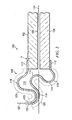
- VIGU 100 includes a pair of glass panes 102 and 104 separated by insulating gap 106.
- a flexible edge seal (herein also called a "FES") 108 is hermetically attached between the panes 102, 104 around their entire periphery, thereby defining an interior space 110 in communication with the gap 106.
- the gap 106 and space 110 may be evacuated (or partially evacuated), to provide a thermal barrier between panes 102 and 104.
- the flexible edge seal 108 includes an elongate first edge seal portion 116 defining a first longitudinal axis 117 and an elongate second edge seal portion 118 defining a second longitudinal axis 119, the longitudinal axes 117 and 119 being oriented generally parallel to the adjacent edge of the glass panes 102 and 104, respectively.
- the first edge seal portion 116 has a substantially constant cross-section when viewed along the first longitudinal axis 117.
- the cross-section of the first edge seal portion 116 includes a bonding flange 112 at one end, a weld surface 120 at the other end and a first center portion 121 (denoted using broken line in FIG.
- the second edge seal portion has a substantially constant cross-section when viewed along the second longitudinal axis 119.
- the second cross-section includes a bonding flange 112 at one end, a weld surface 120 at the other end and a second center portion 123 (denoted using broken line in FIG. 2 ) therebetween.
- Each bonding flange 112 includes a substantially flat portion adapted for hermetic bonding to the surface of a different one of the pair of glass panes 102 and 104.
- the weld surfaces 120 are hermetically joined to one another along bonding plane 122 to form a hermetic seal therebetween.
- the hermetic joining of the weld surfaces 120 may be accomplished by welding, but is not limited to joints/seals created by welding, provided the resulting joint/seal is hermetic.
- At least one of the first center portion 121 and the second center portion 123 has a convoluted cross-section that is asymmetrical to the other center portion (i.e., with respect to a plane 124 defined by the center of the insulating gap) when viewed parallel to one of the longitudinal axes 117, 119). It will be understood that the substantially constant cross-sections of the first and second edge seal portions 116, 118 will extend adjacent to the straight edges of the panes 102, 104, but may or may not extend into the region adjacent to the corners of the panes.
- the FES 108 has an asymmetric convolute form (i.e., when viewed in cross-section along a line parallel to one of the longitudinal axes 117, 119).
- the FES 108 forms a hermetic seal to maintain the vacuum between the glass panes 102, 104, and at the same time provides the ability to deflect in a manner that allows transient stresses to be relieved, thereby eliminating the issue of the VIGU 100 bowing under differential outer and inner temperatures.
- the physical size and shape of the FES itself will determine its feasibility for implementation in a VIGU component, which subsequently is integrated into window sash frame assembly or into a curtain-wall or storefront assembly.
- the asymmetric arrangement of FES 108 disclosed in FIGS. 1 and 2 minimizes the volume it occupies at the edge of the VIGU 100.
- the edge seal portions 116 and 118 of FES 108 when viewed in cross-section, may include multiple convolutes (i.e., curves) 114 extending away from the panes, creating a bellows-shaped profile.
- convolute refers to a curved section that loops or curves continuously in a single turning direction.
- a convolute may be bounded by an endpoint, by a straight (i.e., uncurved) section, or by another convolute curving in the opposite direction.
- multiple convolutes linked together in series may form a corrugated section.
- the convolutes 114 on one side of the FES 108 are nested within the convolutes on the other side as shown in FIGS. 1 and 2 , thereby minimizing the protrusion of the bellows profile beyond the viewing planes of the glass panes 102 and 104.
- This allows the end-use product developer to integrate the VIGU 100 into the sash frame assembly (not shown) of the window without requiring substantially thicker sash frame profile dimensions.
- the need to accommodate larger deflections, which result from the use of larger pieces of glass panes 102, 104 may be satisfied by increasing the out-of-plane height of the convolutes 114, by adding more convolutes, or by a combination of both, thus extending the overall length and width of the VIGU 100.
- a portion of the nested convolute 114 of the asymmetric FES 108 attached to the inner pane 102 may touch a portion of the nested convolute attached to the outer pane 104 or vice versa, when vacuum is applied. This facilitates resisting collapse under external atmospheric pressure when relatively thin materials are used the FES 108, while at the same time allowing for flexing of the convolutes 114 to allow for movements of inner and outer panes 102, 104 caused by temperature differentials and other forces.
- a portion of the nested convolute 114 of the asymmetric FES 108 attached to either the inner or outer pane 102, 104 may touch the outer edge of the glass (i.e., normal to the glass-to-metal bonding plane) when vacuum is applied. This facilitates resisting collapse under atmospheric pressure with material of relatively small thickness, while at the same time allowing for flexing of the convolutes 114 to allow for movements of inner and outer panes 102, 104 caused by temperature differentials.
- the number of nested convolutes 114 on FES 108 may range from one to six, depending on the size and configuration of the glass panes 102, 104.
- the FES 108 of VIGU 100 may be formed from stainless steel, carbon steel, titanium, aluminum, or other metals.
- the FES 108 is formed from stainless steel having a thickness within the range from about 0.004 inch to about 0.030 inch.
- the FES 108 is formed from a superferritic stainless steel, e.g., AL 29-4C® a superferritic stainless steel available from ATI Allegheny Ludlum Corporation of Pittsburgh, Pennsylvania.
- the FES 108 is formed from a ferritic stainless steel, e.g., Grade 430, a ferritic stainless steel available from a variety of commercial sources.
- the flanges 112 of the FES 108 may be tapered in thickness in the region where they are bonded to the panes 102, 104, thereby defining an angle A ( FIG. 2 ) between the upper and lower surfaces of the flange ranging from about 2 degrees to about 10 degrees.
- the tapering of the flanges 112 is believed to aid in achieving minimal stress in the glass-to-metal joint.
- the thinnest portion of the flange material is oriented toward the middle of the glass pane, increasing in thickness further towards the outside edge of the assembly.
- the described (preferably asymmetric) FES 108 may be formed from a first portion 116 and a second portion 118 that are hermetically joined at the outermost surfaces 120 (i.e., the surfaces farthest from the flanges 112).
- welding will be used to join the portions 116, 118, however, other sealing technologies may be used, provided the result is a hermetically-tight, physically strong joint.
- the respective portions 116, 118 may be configured to provide for weld joint alignment, placement of the weld and subsequent handling protection for the finished component. For example, in the embodiment shown in FIGS.
- the bonding plane 122 defined between the weld surfaces 120 is oriented substantially perpendicular to the plane 124 between the panes 102, 104.
- the portions 116 and 118 may be configured to provide interference angles at the welded joint surfaces 120 to facilitate the alignment of the edges to be subsequently welded.
- the bonding plane 122 between the weld surfaces 120 is oriented so that it is easily hermetically sealed, using one of the following methods: laser welding; electron beam welding; seam welding; solder joining; resistance welding; and TIG welding.
- the portion of the (preferably asymmetric) FES 108 that is to be welded may be located in a plane (e.g., plane 122) that is normal to the plane 124 of the glass-to-metal joint and as such is configured in such a manner that risk of handling damage to the joint and to the FES itself is minimized.
- a plane e.g., plane 122
- the inside radius R of corners 126 may range from about 0.15 inch to about 0.75 inch. In preferred embodiments, the inside radius R of corners 126 may range from about 0.15 inch to about 0.50 inch
- the asymmetric FES 108 may be formed by one or more of the following methods to ensure reliable glass-to-metal bonding, reliable welding and vacuum leak-free performance.
- the FES 108 may be cut from a single sheet to required width, and then progressively die formed to provide uniform convolutes 114, corners 126 and straight lengths 128 to develop a finished unit corresponding to the ordered size.
- straight lengths of strip may be slit to the required width, cut to appropriate length, welded at the corners and progressively die-formed to provide uniform convolutes 114, corners 126 and straight lengths 128 to develop a finished FES unit 108 corresponding to the ordered size.
- straight lengths of strip may be slit to the required width, roll-formed to provide uniform convolutes 114, cut to required lengths and then welded to discrete, formed corner pieces, to develop a finished FES unit 108 corresponding to the ordered size.
- Welding methods believed suitable for forming the FES 108 include: laser welding, electron beam welding and TIG welding.
- Comer-forming methods believed suitable for forming the FES 108 include hot isostatic press, hot and cold drawing and forming, forging and spin forming.
- this asymmetrical flexible edge seal for vacuum insulating glass provides an airtight (e.g., hermetic) flexible edge seal between the spaced-apart panes of an insulating glazing device.
- airtight e.g., hermetic
Landscapes
- Engineering & Computer Science (AREA)
- Civil Engineering (AREA)
- Structural Engineering (AREA)
- Joining Of Glass To Other Materials (AREA)
- Securing Of Glass Panes Or The Like (AREA)
Claims (15)
- Joint d'étanchéité de bord souple pour unité de vitrage isolant sous vide comprenant deux vitres séparées par un espace isolant, le joint d'étanchéité de bord souple comprenant :une première partie de joint de bord allongée définissant un premier axe longitudinal, la première partie de joint de bord ayant une première section transversale substantiellement constante, vue le long du premier axe longitudinal, la première section transversale incluant une bride de liaison à une extrémité, une surface de soudage à l'autre extrémité et une première partie centrale entre les deux ;une deuxième partie de joint de bord allongée définissant un deuxième axe longitudinal substantiellement parallèle au premier axe longitudinal, la deuxième partie de joint de bord ayant une deuxième section transversale substantiellement constante, vue le long du deuxième axe longitudinal, la deuxième section transversale incluant une bride de liaison à une extrémité, une surface de soudage à l'autre extrémité et une deuxième partie centrale entre les deux ;dans lequel chaque bride de liaison comprend une partie substantiellement plate adaptée pour une liaison hermétique sur une surface d'une vitre différente parmi les deux vitres ;dans lequel les surfaces de soudage sont liées hermétiquement l'une à l'autre en formant un joint hermétique entre elles ;dans lequel au moins l'une des première partie centrale et deuxième partie centrale a une section transversale sinueuse et est asymétrique, par rapport à un plan défini par le centre de l'espace isolant, à l'autre partie centrale ;caractérisé en ce qu'au moins l'une des première partie centrale et deuxième partie centrale comprend plusieurs sinuosités.
- Joint d'étanchéité de bord souple selon la revendication 1, dans lequel la première partie centrale et la deuxième partie centrale comprennent au moins une sinuosité.
- Joint d'étanchéité de bord souple selon la revendication 2, dans lequel la première partie centrale comprend un nombre de sinuosités différent de celui de la deuxième partie centrale.
- Joint d'étanchéité de bord souple selon la revendication 2, dans lequel la première partie centrale et la deuxième partie centrale comprennent plusieurs sinuosités.
- Joint d'étanchéité de bord souple selon la revendication 4, dans lequel le nombre de sinuosités sur chacune des première et deuxième parties centrales est compris dans l'intervalle de deux sinuosités à six sinuosités.
- Joint d'étanchéité de bord souple selon la revendication 2, dans lequel au moins l'une des sinuosités de l'une des première et deuxième parties centrales traverse le plan défini par le centre de l'espace isolant et se niche au moins en partie dans une sinuosité de l'autre des parties centrales.
- Joint d'étanchéité de bord souple selon la revendication 1, dans lequel les surfaces supérieure et inférieure d'au moins l'une des brides de liaison définissent un angle de rétrécissement l'une par rapport à l'autre, de sorte que l'épaisseur de la bride de liaison diminue dans la région adaptée pour la liaison avec la vitre.
- Joint d'étanchéité de bord souple selon la revendication 7, dans lequel l'angle de rétrécissement est compris dans l'intervalle d'environ 2 degrés à environ 10 degrés.
- Unité de vitrage isolant sous vide comprenant :deux vitres séparées par un espace isolant et un joint d'étanchéité de bord souple, le joint d'étanchéité de bord souple comprenant :une première partie de joint de bord allongée définissant un premier axe longitudinal, la première partie de joint de bord ayant une première section transversale substantiellement constante, vue le long du premier axe longitudinal, la première section transversale incluant une bride de liaison à une extrémité, une surface de soudage à l'autre extrémité et une première partie centrale entre les deux ;une deuxième partie de joint de bord allongée définissant un deuxième axe longitudinal substantiellement parallèle au premier axe longitudinal, la deuxième partie de joint de bord ayant une deuxième section transversale substantiellement constante, vue le long du deuxième axe longitudinal, la deuxième section transversale incluant une bride de liaison à une extrémité, une surface de soudage à l'autre extrémité et une deuxième partie centrale entre les deux ;chaque bride de liaison comprenant une partie substantiellement plate liée de façon hermétique à une surface d'une vitre différente parmi les deux vitres ;les surfaces de soudage étant liées hermétiquement l'une à l'autre en formant un joint hermétique entre elles ;au moins l'une des première partie centrale et deuxième partie centrale ayant une section transversale sinueuse et étant asymétrique, par rapport à un plan défini par le centre de l'espace isolant, à l'autre partie centrale ;caractérisée en ce qu'au moins l'une des première partie centrale et deuxième partie centrale comprend plusieurs sinuosités.
- Unité de vitrage isolant sous vide selon la revendication 9, dans laquelle la première partie centrale et la deuxième partie centrale comprennent au moins une sinuosité.
- Unité de vitrage isolant sous vide selon la revendication 10, dans laquelle la première partie centrale comprend un nombre de sinuosités différent de celui de la deuxième partie centrale.
- Unité de vitrage isolant sous vide selon la revendication 10, dans laquelle le nombre de sinuosités sur chacune des première et deuxième parties centrales est compris dans l'intervalle de deux sinuosités à six sinuosités.
- Unité de vitrage isolant sous vide selon la revendication 10, dans laquelle au moins l'une des sinuosités de l'une des première et deuxième parties centrales traverse le plan défini par le centre de l'espace isolant et se niche au moins en partie dans une sinuosité de l'autre des parties centrales.
- Unité de vitrage isolant sous vide selon la revendication 9, dans laquelle les surfaces supérieure et inférieure d'au moins l'une des brides de liaison définissent un angle de rétrécissement l'une par rapport à l'autre, de sorte que l'épaisseur de la bride de liaison diminue dans la région adaptée pour la liaison avec la vitre.
- Procédé de formation d'une unité de vitrage isolant sous vide, le procédé comprenant les étapes suivantes :fournir deux vitres séparées par un espace isolant ;fournir une première partie de joint de bord allongée définissant un premier axe longitudinal, la première partie de joint de bord ayant une première section transversale substantiellement constante, vue le long du premier axe longitudinal, la première section transversale incluant une bride de liaison à une extrémité, une surface de soudage à l'autre extrémité et une première partie centrale entre les deux ;fournir une deuxième partie de joint de bord allongée définissant un deuxième axe longitudinal substantiellement parallèle au premier axe longitudinal, la deuxième partie de joint de bord ayant une deuxième section transversale substantiellement constante, vue le long du deuxième axe longitudinal, la deuxième section transversale incluant une bride de liaison à une extrémité, une surface de soudage à l'autre extrémité et une deuxième partie centrale entre les deux ;dans lequel au moins l'une des première partie centrale et deuxième partie centrale a une section transversale sinueuse et est asymétrique, par rapport à un plan défini par le centre de l'espace isolant, à l'autre partie centrale ;dans lequel au moins l'une des première partie centrale et deuxième partie centrale comprend plusieurs sinuosités ;lier hermétiquement la bride de liaison de chacune des première et deuxième parties de joint de bord avec une surface d'une vitre différente parmi les deux vitres ;évacuer au moins partiellement l'atmosphère présente dans l'espace situé entre les vitres ; etlier hermétiquement les surfaces de soudage l'une à l'autre en formant un joint hermétique entre elles.
Applications Claiming Priority (2)
| Application Number | Priority Date | Filing Date | Title |
|---|---|---|---|
| US8763608P | 2008-08-09 | 2008-08-09 | |
| PCT/US2009/053206 WO2010019484A2 (fr) | 2008-08-09 | 2009-08-07 | Joint d'étanchéité à bord souple asymétrique pour vitrage isolant vis-à-vis du vide |
Publications (2)
| Publication Number | Publication Date |
|---|---|
| EP2324183A2 EP2324183A2 (fr) | 2011-05-25 |
| EP2324183B1 true EP2324183B1 (fr) | 2014-06-25 |
Family
ID=41509022
Family Applications (1)
| Application Number | Title | Priority Date | Filing Date |
|---|---|---|---|
| EP09744250.3A Not-in-force EP2324183B1 (fr) | 2008-08-09 | 2009-08-07 | Joint d'étanchéité à bord souple asymétrique pour vitrage isolant vis-à-vis du vide |
Country Status (3)
| Country | Link |
|---|---|
| US (1) | US8283023B2 (fr) |
| EP (1) | EP2324183B1 (fr) |
| WO (1) | WO2010019484A2 (fr) |
Families Citing this family (17)
| Publication number | Priority date | Publication date | Assignee | Title |
|---|---|---|---|---|
| US8131370B2 (en) * | 2007-01-18 | 2012-03-06 | Medtronic, Inc | Methods of manufacturing a hermetic lead connector |
| WO2010019484A2 (fr) | 2008-08-09 | 2010-02-18 | Eversealed Windows, Inc. | Joint d'étanchéité à bord souple asymétrique pour vitrage isolant vis-à-vis du vide |
| US8512830B2 (en) | 2009-01-15 | 2013-08-20 | Eversealed Windows, Inc. | Filament-strung stand-off elements for maintaining pane separation in vacuum insulating glazing units |
| WO2010083476A2 (fr) * | 2009-01-15 | 2010-07-22 | Eversealed Windows, Inc | Joint de bordure souple pour unité de vitrage pour isolation sous vide |
| US9689195B2 (en) | 2010-03-27 | 2017-06-27 | Robert S. Jones | Vacuum insulating glass unit with viscous edge seal |
| CA2793476C (fr) | 2010-03-27 | 2018-05-01 | Robert S. Jones | Vitrage isolant sous vide avec joint peripherique visqueux |
| US9732552B2 (en) | 2010-03-27 | 2017-08-15 | Robert S. Jones | Vacuum insulating glass unit with viscous edge seal |
| DE102010021127B4 (de) * | 2010-05-21 | 2021-11-04 | Grenzebach Maschinenbau Gmbh | Verfahren zum Herstellen von Mehrscheiben-Isolierglas mit einer Hochvakuum-Isolierung |
| WO2011153381A2 (fr) | 2010-06-02 | 2011-12-08 | Eversealed Windows, Inc. | Unité de vitrage à pluralité de vitres comprenant un joint avec une couche de revêtement adhésive et hermétique |
| US9328512B2 (en) | 2011-05-05 | 2016-05-03 | Eversealed Windows, Inc. | Method and apparatus for an insulating glazing unit and compliant seal for an insulating glazing unit |
| BE1021707B1 (fr) * | 2013-01-11 | 2016-01-11 | Agc Glass Europe | Panneau de vitrage avec joint d'etancheite peripherique et procede de fabrication correspondant. |
| CA2958414C (fr) | 2013-10-18 | 2021-11-16 | Eversealed Windows, Inc. | Ensembles de joint de bord pour unites de verre isolantes (igu) hermetiques et unites de verre isolantes sous vide (vigu) |
| US10465435B2 (en) | 2017-02-06 | 2019-11-05 | Cardinal Cg Company | Thermally insulative gas replacement system for vacuum insulating glass units |
| WO2020118667A1 (fr) * | 2018-12-11 | 2020-06-18 | 淄博环能海臣环保技术服务有限公司 | Plaque de verre d'isolation thermique régulée sous vide pourvue d'une cavité d'espaceur en verre scellée à double adhésif de support de presse à rouleaux |
| EP3911816B1 (fr) * | 2019-01-14 | 2025-05-07 | VKR Holding A/S | Fenêtre de toit basculante à châssis comprenant une unité de verre isolée sous vide chevauchant un profil de cadre inférieur |
| US11313611B2 (en) * | 2019-05-01 | 2022-04-26 | Whirlpool Corporation | Construction method for vacuum insulated door |
| JP2024500992A (ja) * | 2021-01-27 | 2024-01-10 | サン-ゴバン グラス フランス | 遮断グレージングのためのスペーサ |
Family Cites Families (182)
| Publication number | Priority date | Publication date | Assignee | Title |
|---|---|---|---|---|
| US49167A (en) * | 1865-08-01 | Improvement in window-glass | ||
| US1127381A (en) * | 1908-05-12 | 1915-02-02 | Clarence P Byrnes | Method of forming glass vacuum-receptacles. |
| US988308A (en) * | 1910-04-18 | 1911-04-04 | Vacuum Glass Company | Incandescent lamp. |
| US1004257A (en) * | 1910-11-29 | 1911-09-26 | Orlando J W Higbee | Process of manufacturing glass vacuum-wall bottles. |
| US1388126A (en) * | 1920-03-20 | 1921-08-16 | Vacuum Glass Machine Company | Process of manufacturing vacuum wall-containers |
| US1436197A (en) * | 1921-04-02 | 1922-11-21 | Vacuum Glass Machine Company | Machine for the manufacture of vacuum-wall containers |
| US1560690A (en) * | 1923-04-21 | 1925-11-10 | Western Electric Co | Electron-discharge device |
| US2011557A (en) * | 1933-12-07 | 1935-08-20 | Frederick O Anderegg | Window structure |
| US2119009A (en) * | 1935-06-27 | 1938-05-31 | Nathaniel M Elias | Vacuum jacketed glass tube and shape |
| US2057969A (en) * | 1935-08-13 | 1936-10-20 | American Thermos Bottle Co | Double-walled vacuum receptacle |
| US2220690A (en) * | 1937-03-09 | 1940-11-05 | Stupakoff Lab Inc | Glass and metal construction unit |
| US2206558A (en) * | 1937-07-09 | 1940-07-02 | Willard H Bennett | High voltage vacuum tube |
| US2177001A (en) * | 1938-05-07 | 1939-10-24 | Pittsburgh Plate Glass Co | Double glazed window |
| US2625717A (en) * | 1945-06-12 | 1953-01-20 | Libbey Owens Ford Glass Co | Multiple sheet glazing unit |
| US2708774A (en) * | 1949-11-29 | 1955-05-24 | Rca Corp | Multiple glazed unit |
| US2756467A (en) * | 1952-11-05 | 1956-07-31 | Etling Birtus Oliver | Multiple-pane glazing unit and manufacture thereof |
| US2730987A (en) * | 1954-03-25 | 1956-01-17 | James L Entwistle Company | Apparatus for automatically vacuum coating of interior of glass tubes with metal |
| AT305405B (de) * | 1970-12-30 | 1973-02-26 | Electrovac | Plattenstapel und Verfahren zu dessen Herstellung |
| US3232732A (en) * | 1961-02-06 | 1966-02-01 | George L Wax | Insulating container and method of making same |
| US3389522A (en) * | 1966-04-20 | 1968-06-25 | Hordis Brothers | Glass unit and method |
| US3674667A (en) * | 1969-07-23 | 1972-07-04 | Allis Chalmers Mfg Co | Process for increasing water repellency of cotton cloth |
| US3698878A (en) * | 1969-12-29 | 1972-10-17 | Gen Electric | Sintered tungsten carbide-base alloys |
| FR2085464B1 (fr) * | 1970-04-23 | 1974-08-09 | Saint Gobain Pont A Mousson | |
| US3778127A (en) * | 1971-12-30 | 1973-12-11 | Ibm | Sealing technique for gas panel |
| DE2203943C2 (de) * | 1972-01-28 | 1974-02-21 | Flachglas Ag Delog-Detag, 8510 Fuerth | Wärmerefexionsscheibe, die gute Farbgleichmäßigkeit aufweist, Verfahren zu ihrer Herstellung sowie ihre Verwendung |
| NL7210011A (fr) * | 1972-07-20 | 1974-01-22 | ||
| US4063271A (en) * | 1972-07-26 | 1977-12-13 | Texas Instruments Incorporated | FET and bipolar device and circuit process with maximum junction control |
| US3828960A (en) * | 1972-11-10 | 1974-08-13 | Dow Chemical Co | Heat insulating container having plastic walls retaining vacuum |
| US3922705A (en) * | 1973-06-04 | 1975-11-25 | Gen Electric | Dielectrically isolated integral silicon diaphram or other semiconductor product |
| DE2338192C2 (de) * | 1973-07-27 | 1975-05-15 | Philips Patentverwaltung Gmbh, 2000 Hamburg | Vorrichtung zur Dichtheitsprüfung von vakuumdichten Glasverschmelzungen |
| US3940898A (en) * | 1973-08-20 | 1976-03-02 | K.T. Corporation | Double-pane window containing dry atmosphere and method for producing same |
| US4016644A (en) * | 1974-03-18 | 1977-04-12 | Kulite Semiconductor Products, Inc. | Methods of fabricating low pressure silicon transducers |
| US3971178A (en) * | 1974-03-25 | 1976-07-27 | Ppg Industries, Inc. | Add-on multiple glazing with hygroscopic material |
| US3990201A (en) * | 1974-09-03 | 1976-11-09 | Gerald Falbel | Evacuated dual glazing system |
| NO145771C (no) * | 1974-09-16 | 1982-05-26 | Bfg Glassgroup | Lysgjennomslippende panel |
| US4060660A (en) * | 1976-01-15 | 1977-11-29 | Rca Corporation | Deposition of transparent amorphous carbon films |
| US4035539A (en) * | 1976-05-12 | 1977-07-12 | Luboshez Sergius N Ferris | Structural panel |
| US4099082A (en) * | 1976-10-06 | 1978-07-04 | Zenith Radio Corporation | Stacked lattice spacer support for luminescent display panels |
| GB1558986A (en) * | 1976-12-10 | 1980-01-09 | Bennett C J | Spacers for vacuum enclosures |
| US4089143A (en) * | 1977-03-28 | 1978-05-16 | James W. Mulvihill | Method of converting single pane glass to multiple pane, hermetically sealed insulating glass without removing the existing glass sash and frame |
| US4186725A (en) * | 1978-03-29 | 1980-02-05 | Schwartz David M | Solar energy collector |
| US4204015A (en) * | 1978-04-03 | 1980-05-20 | Levine Robert A | Insulating window structure and method of forming the same |
| US4274936A (en) * | 1979-04-30 | 1981-06-23 | Advanced Coating Technology, Inc. | Vacuum deposition system and method |
| NL7904283A (nl) * | 1979-05-31 | 1980-12-02 | Philips Nv | Koppelelement met een lichtbron en en lensvormig element. |
| US4303732A (en) * | 1979-07-20 | 1981-12-01 | Torobin Leonard B | Hollow microspheres |
| US4261086A (en) * | 1979-09-04 | 1981-04-14 | Ford Motor Company | Method for manufacturing variable capacitance pressure transducers |
| US4357187A (en) * | 1980-08-18 | 1982-11-02 | Glenn Stanley | Window overlay for thermal insulation |
| JPS5812680Y2 (ja) * | 1980-11-20 | 1983-03-11 | 象印マホービン株式会社 | ステンレス鋼製魔法瓶 |
| US4444821A (en) * | 1982-11-01 | 1984-04-24 | General Electric Company | Vacuum thermal insulation panel |
| US4468423A (en) * | 1982-11-17 | 1984-08-28 | Arlie Hall | Insulating cell element and structures composed thereof |
| US4486482A (en) * | 1983-06-15 | 1984-12-04 | Hitachi, Ltd. | Vacuum heat insulator |
| US4531511A (en) * | 1983-07-14 | 1985-07-30 | Hochberg Nelson D | Means for controlling heat flux |
| US4547432A (en) * | 1984-07-31 | 1985-10-15 | The United States Of America As Represented By The United States Department Of Energy | Method of bonding silver to glass and mirrors produced according to this method |
| US4649085A (en) * | 1984-08-29 | 1987-03-10 | The United States Of America As Represented By The Secretary Of The Air Force | Cryogenic glass-to-metal seal |
| GB8508092D0 (en) * | 1985-03-28 | 1985-05-01 | Glaverbel | Transparent glazing panels |
| US4683154A (en) * | 1985-08-19 | 1987-07-28 | The United States Of America As Represented By The United States Department Of Energy | Laser sealed vacuum insulation window |
| US4737475A (en) * | 1985-10-07 | 1988-04-12 | General Electric Company | Arsenic-free lead silicate vacuum tube glass |
| RU94045909A (ru) * | 1985-11-29 | 1996-09-10 | Бехли Эмиль | Способ изготовления теплоизоляционного строительного и/или светового элемента и устройство для его осуществления |
| US4780164A (en) * | 1986-11-20 | 1988-10-25 | Cardinal Ig Company | Method for producing gas-containing insulating glass assemblies |
| US5525430A (en) * | 1986-12-31 | 1996-06-11 | Chahroudi; Day | Electrically activated thermochromic optical shutters |
| US5355245A (en) | 1988-02-12 | 1994-10-11 | Donnelly Corporation | Ultraviolet protected electrochemichromic rearview mirror |
| US5175975A (en) * | 1988-04-15 | 1993-01-05 | Midwest Research Institute | Compact vacuum insulation |
| US5157893A (en) * | 1988-04-15 | 1992-10-27 | Midwest Research Institute | Compact vacuum insulation |
| US5318108A (en) * | 1988-04-15 | 1994-06-07 | Midwest Research Institute | Gas-controlled dynamic vacuum insulation with gas gate |
| US5107649A (en) * | 1988-04-15 | 1992-04-28 | Midwest Research Institute | Compact vacuum insulation embodiments |
| US4928448A (en) * | 1988-05-02 | 1990-05-29 | Enhanced Insulations, Inc. | Thermally insulating window and method of forming |
| EP0346815A3 (fr) * | 1988-06-13 | 1990-12-19 | Asahi Glass Company Ltd. | Dispositif de traitement sous vide et son système de transport |
| US5846638A (en) * | 1988-08-30 | 1998-12-08 | Onyx Optics, Inc. | Composite optical and electro-optical devices |
| US5589239A (en) * | 1988-11-02 | 1996-12-31 | Canon Kabushiki Kaisha | Variable-angle optical device with optically transparent substance |
| US5017252A (en) * | 1988-12-06 | 1991-05-21 | Interpane Coatings, Inc. | Method for fabricating insulating glass assemblies |
| JPH02225346A (ja) * | 1989-02-27 | 1990-09-07 | Central Glass Co Ltd | 熱線反射ガラス |
| US5115299A (en) * | 1989-07-13 | 1992-05-19 | Gte Products Corporation | Hermetically sealed chip carrier with ultra violet transparent cover |
| ATE103366T1 (de) * | 1989-07-16 | 1994-04-15 | Emil Baechli | Gasdichte randdichtung und verfahren zu deren herstellung. |
| US5014466A (en) * | 1989-07-28 | 1991-05-14 | Kurt Winner | Window assembly |
| US5657607A (en) * | 1989-08-23 | 1997-08-19 | University Of Sydney | Thermally insulating glass panel and method of construction |
| US5032439A (en) * | 1989-08-25 | 1991-07-16 | Massachusetts Institute Of Technology | Thermal insulations using vacuum panels |
| US5270084A (en) * | 1989-09-28 | 1993-12-14 | Parker Design Limited | Insulating glass unit |
| US5124185A (en) * | 1989-10-03 | 1992-06-23 | Ppg Industries, Inc. | Vacuum insulating unit |
| US5115612A (en) * | 1990-03-14 | 1992-05-26 | Vacuglas, Inc. | Transparent thermal panel |
| DE69016433T2 (de) * | 1990-05-19 | 1995-07-20 | Papyrin Anatolij Nikiforovic | Beschichtungsverfahren und -vorrichtung. |
| US5527596A (en) * | 1990-09-27 | 1996-06-18 | Diamonex, Incorporated | Abrasion wear resistant coated substrate product |
| US5118924A (en) * | 1990-10-01 | 1992-06-02 | Eastman Kodak Company | Static control overlayers on opto-electronic devices |
| JP2929779B2 (ja) * | 1991-02-15 | 1999-08-03 | トヨタ自動車株式会社 | 炭素被膜付撥水ガラス |
| ATE152205T1 (de) * | 1991-10-25 | 1997-05-15 | Luc Lafond | Isolierprofil und verfahren für einfache und mehrfache atmosphärisch isolierende baueinheiten |
| US5330816A (en) * | 1992-12-23 | 1994-07-19 | Owens-Corning Fiberglas Technology Inc. | High R super insulation panel |
| JP2662365B2 (ja) * | 1993-01-28 | 1997-10-08 | アプライド マテリアルズ インコーポレイテッド | 改良された排出システムを有する単一基板式の真空処理装置 |
| KR100250396B1 (ko) | 1993-06-30 | 2000-04-01 | 앤더슨 데릭 제이. | 진공 글레이징의 구조방법 |
| DK0645516T3 (da) * | 1993-09-27 | 2002-05-13 | Saint Gobain | Fremgangsmåde til frembringelse af vakuum i en isoleringsrude samt en isoleringsrude |
| JPH07142627A (ja) * | 1993-11-18 | 1995-06-02 | Fujitsu Ltd | 半導体装置及びその製造方法 |
| US5423119A (en) * | 1994-07-08 | 1995-06-13 | Hualon Microelectronics Corporation | Method for manufacturing a hybrid circuit charge-coupled device image sensor |
| US5489321A (en) * | 1994-07-14 | 1996-02-06 | Midwest Research Institute | Welding/sealing glass-enclosed space in a vacuum |
| JP3345518B2 (ja) * | 1994-09-28 | 2002-11-18 | 株式会社東芝 | 光半導体モジュールの製造方法 |
| AUPM888994A0 (en) | 1994-10-19 | 1994-11-10 | University Of Sydney, The | Design improvement to vacuum glazing |
| US5789857A (en) * | 1994-11-22 | 1998-08-04 | Futaba Denshi Kogyo K.K. | Flat display panel having spacers |
| US5610431A (en) * | 1995-05-12 | 1997-03-11 | The Charles Stark Draper Laboratory, Inc. | Covers for micromechanical sensors and other semiconductor devices |
| US5759753A (en) | 1995-07-19 | 1998-06-02 | Matsushita Electric Industrial Co., Ltd. | Piezoelectric device and method of manufacturing the same |
| US5778629A (en) * | 1995-09-28 | 1998-07-14 | Howes; Stephen E. | Impact resistant window |
| US6101783A (en) | 1995-09-28 | 2000-08-15 | Howes; Stephen E. | Impact resistant window |
| US5937611A (en) | 1995-09-28 | 1999-08-17 | Howes; Stephen E. | Method of making an impact resistant window |
| US5811926A (en) * | 1996-06-18 | 1998-09-22 | Ppg Industries, Inc. | Spacer units, image display panels and methods for making and using the same |
| US5983593A (en) | 1996-07-16 | 1999-11-16 | Dow Corning Corporation | Insulating glass units containing intermediate plastic film and method of manufacture |
| US5856914A (en) * | 1996-07-29 | 1999-01-05 | National Semiconductor Corporation | Micro-electronic assembly including a flip-chip mounted micro-device and method |
| MXPA99005203A (es) | 1996-12-05 | 2006-07-18 | Sashlite Llc | Unidad de ventana con cristales multiples integrados y montaje de marco y metodo para fabricarlo. |
| US6109994A (en) | 1996-12-12 | 2000-08-29 | Candescent Technologies Corporation | Gap jumping to seal structure, typically using combination of vacuum and non-vacuum environments |
| CN1139966C (zh) | 1997-03-21 | 2004-02-25 | 佳能株式会社 | 图象形成设备 |
| CA2234281C (fr) | 1997-04-11 | 2006-10-17 | Jean-Michel Florentin | Paroi ou porte d'enceinte climatique |
| US5897927A (en) * | 1997-06-30 | 1999-04-27 | Industrial Technology Research Institute | Seal for vacuum devices and methods for making same |
| US6020628A (en) | 1997-07-21 | 2000-02-01 | Olin Corporation | Optical component package with a hermetic seal |
| JP2993472B2 (ja) | 1997-07-30 | 1999-12-20 | 住友電気工業株式会社 | 光半導体用気密封止容器及び光半導体モジュール |
| US5949655A (en) | 1997-09-09 | 1999-09-07 | Amkor Technology, Inc. | Mounting having an aperture cover with adhesive locking feature for flip chip optical integrated circuit device |
| DE29718449U1 (de) | 1997-10-17 | 1999-02-11 | Robert Bosch Gmbh, 70469 Stuttgart | Bauelementefixierung bei elektrischem Steuergerät |
| KR100255129B1 (ko) | 1997-12-26 | 2000-05-01 | 박호군 | 유리기판 사이의 접합을 이용한 전계방출표시소자 진공 실장 장치 및 방법 |
| US6066299A (en) | 1998-01-09 | 2000-05-23 | Q.I.S., Inc. | Limited volume insert bonded in a vial |
| US6141925A (en) | 1998-03-10 | 2000-11-07 | Steelcase Development Inc. | Clear wall panel system |
| US6131410A (en) | 1998-03-16 | 2000-10-17 | The Regents Of The University Of California | Vacuum fusion bonding of glass plates |
| CN1266414A (zh) | 1998-05-01 | 2000-09-13 | 日本板硝子株式会社 | 玻璃面板和玻璃面板的制造方法及用于玻璃面板中的隔垫 |
| JPH11315668A (ja) | 1998-05-07 | 1999-11-16 | Nippon Sheet Glass Co Ltd | ガラスパネル |
| CN1273621A (zh) | 1998-07-14 | 2000-11-15 | 日本板硝子株式会社 | 玻璃面板及其形成方法 |
| DE19840640A1 (de) | 1998-09-05 | 2000-03-16 | Isovac Ingenieurgesellschaft M | Isoliergehäuse, insbesondere für Kühlgeräte und/oder Energiespeicher |
| US6191359B1 (en) | 1998-10-13 | 2001-02-20 | Intel Corporation | Mass reflowable windowed package |
| US5950398A (en) | 1998-10-22 | 1999-09-14 | Hubbard; Bruce M. | Pass-by insulating glass window unit and method for replacing single glazing |
| CA2368449A1 (fr) | 1999-03-25 | 2000-10-05 | Nippon Sheet Glass Co., Ltd. | Panneau de verre et son procede de production |
| US6336984B1 (en) | 1999-09-24 | 2002-01-08 | Guardian Industries Corporation | Vacuum IG window unit with peripheral seal at least partially diffused at temper |
| US6291036B1 (en) | 1999-05-03 | 2001-09-18 | Guardian Industries Corporation | Vacuum IG window unit with spacers in seal |
| FR2793950A1 (fr) | 1999-05-21 | 2000-11-24 | Thomson Plasma | Procede de fabrication de composants sur substrats de verre devant etre scelles, tels que des ecrans d'affichage plats du type panneau a plasma |
| EP1101001B1 (fr) | 1999-05-26 | 2004-02-25 | GLASFABRIK LAMBERTS GMBH & CO. KG | Dispositif pour retenir des elements profiles en verre et rail de support |
| AUPQ090299A0 (en) | 1999-06-10 | 1999-07-01 | University Of Sydney, The | Glass panel |
| US6139913A (en) | 1999-06-29 | 2000-10-31 | National Center For Manufacturing Sciences | Kinetic spray coating method and apparatus |
| US6365242B1 (en) | 1999-07-07 | 2002-04-02 | Guardian Industries Corp. | Peripheral seal for vacuum IG window unit |
| US6399169B1 (en) | 1999-07-07 | 2002-06-04 | Guardian Industries Corp. | Vacuum IG window unit with dual peripheral seal |
| US6420002B1 (en) | 1999-08-18 | 2002-07-16 | Guardian Industries Corp. | Vacuum IG unit with spacer/pillar getter |
| US6946171B1 (en) | 1999-09-22 | 2005-09-20 | Guardian Industries Corp. | Vacuum IG pillar with lubricating and/or reflective coating |
| US6478911B1 (en) | 2000-09-27 | 2002-11-12 | Guardian Industries Corp. | Vacuum IG window unit with edge seal formed via microwave curing, and corresponding method of making the same |
| US6558494B1 (en) | 1999-09-24 | 2003-05-06 | Guardian Industries Corp. | Vacuum IG window unit with edge seal at least partially diffused at temper and completed via microwave curing, and corresponding method of making the same |
| US6444281B1 (en) | 1999-10-13 | 2002-09-03 | Guardian Industries Corp. | Vacuum IG window unit with spacers between first and second edge seals |
| AUPQ349499A0 (en) | 1999-10-18 | 1999-11-11 | University Of Sydney, The | Method of producing support pillars |
| US6383580B1 (en) | 1999-11-12 | 2002-05-07 | Guardian Industries Corp. | Vacuum IG window unit with edge mounted pump-out tube |
| US6503583B2 (en) | 1999-11-16 | 2003-01-07 | Guardian Industries Corp. | Vacuum IG window unit with fiber inclusive edge seal |
| US6436492B1 (en) | 1999-11-16 | 2002-08-20 | Guardian Industries Corp. | Vacuum IG window unit with fiber spacers |
| US6352749B1 (en) | 1999-12-10 | 2002-03-05 | Guardian Industries Corp. | Vacuum IG unit with transparent spacers |
| US6541083B1 (en) | 2000-01-11 | 2003-04-01 | Guardian Industries Corp. | Vacuum IG unit with alkali silicate edge seal and/or spacers |
| US6497931B1 (en) | 2000-01-11 | 2002-12-24 | Guardian Industries Corp. | Vacuum IG unit with colored spacers |
| DE50002987D1 (de) | 2000-02-01 | 2003-08-28 | Emil Baechli | Einrichtung zur Oberflächenbehandlung und/oder Beschichtung bzw. zur Fertigung von Bauelementen, insbesondere flacher Bauelemente aus Glas, Glaslegierungen oder Metall, im Durchlaufverfahren |
| US6372312B1 (en) | 2000-02-17 | 2002-04-16 | Guardian Industries Corp. | Vacuum IG unit with micro-sized spacers |
| US6656768B2 (en) | 2001-02-08 | 2003-12-02 | Texas Instruments Incorporated | Flip-chip assembly of protected micromechanical devices |
| JP3880278B2 (ja) | 2000-03-10 | 2007-02-14 | オリンパス株式会社 | 固体撮像装置及びその製造方法 |
| DE10014380A1 (de) | 2000-03-23 | 2001-10-04 | Infineon Technologies Ag | Vorrichtung zum Verpacken von elektronischen Bauteilen |
| US6506272B1 (en) | 2000-04-04 | 2003-01-14 | Guardian Industries Corp. | Vacuum IG unit with seal for pump-out aperture |
| US6384473B1 (en) | 2000-05-16 | 2002-05-07 | Sandia Corporation | Microelectronic device package with an integral window |
| US7114306B2 (en) | 2000-06-14 | 2006-10-03 | Nippon Sheet Glass Co., Ltd. | Glass panel |
| WO2002014640A1 (fr) | 2000-08-11 | 2002-02-21 | Anthony John Cooper | Double vitrage |
| US6701749B2 (en) | 2000-09-27 | 2004-03-09 | Guardian Industries Corp. | Vacuum IG window unit with edge seal at least partially diffused at temper and completed via microwave curing, and corresponding method of making the same |
| JP2002110751A (ja) | 2000-10-03 | 2002-04-12 | Hitachi Ltd | 半導体集積回路装置の検査装置および製造方法 |
| EP1221526A1 (fr) | 2001-01-09 | 2002-07-10 | Emil BÄCHLI | Procédé ainsi qu' installation pour la fabrication d' éléments thermo-isolants de construction et/ou d'éclairage |
| KR100396551B1 (ko) | 2001-02-03 | 2003-09-03 | 삼성전자주식회사 | 웨이퍼 레벨 허메틱 실링 방법 |
| US6541084B2 (en) | 2001-02-05 | 2003-04-01 | Guardian Industries Corp. | Vacuum IG window unit with polymer spacers |
| US6548895B1 (en) | 2001-02-21 | 2003-04-15 | Sandia Corporation | Packaging of electro-microfluidic devices |
| US6662523B2 (en) | 2001-06-15 | 2003-12-16 | Sashlite, Llc | Insulating glass sash assemblies with adhesive mounting and spacing structures |
| US6692600B2 (en) | 2001-09-14 | 2004-02-17 | Guardian Industries Corp. | VIG evacuation with plasma excitation |
| US6679013B2 (en) | 2001-11-15 | 2004-01-20 | Sashlite, Llc | Window assembly with hinged components |
| JP2003192400A (ja) | 2001-12-25 | 2003-07-09 | Nippon Sheet Glass Co Ltd | ガラスパネル |
| US6639313B1 (en) | 2002-03-20 | 2003-10-28 | Analog Devices, Inc. | Hermetic seals for large optical packages and the like |
| US6627814B1 (en) | 2002-03-22 | 2003-09-30 | David H. Stark | Hermetically sealed micro-device package with window |
| US7832177B2 (en) | 2002-03-22 | 2010-11-16 | Electronics Packaging Solutions, Inc. | Insulated glazing units |
| US6962834B2 (en) | 2002-03-22 | 2005-11-08 | Stark David H | Wafer-level hermetic micro-device packages |
| US20060191215A1 (en) | 2002-03-22 | 2006-08-31 | Stark David H | Insulated glazing units and methods |
| KR100457380B1 (ko) | 2002-05-06 | 2004-11-16 | 삼성전기주식회사 | 광마우스용 칩 온 보드 리드 패키지 및 그에 사용되는렌즈커버 |
| JP4109491B2 (ja) | 2002-05-07 | 2008-07-02 | 日本板硝子株式会社 | 透光性ガラスパネル |
| US6736295B2 (en) | 2002-05-13 | 2004-05-18 | Shin-Shuoh Lin | High flow carafe |
| US6763638B1 (en) | 2002-07-23 | 2004-07-20 | Berger Jr Allen | Window assembly for opening closures |
| US20050217319A1 (en) | 2002-12-05 | 2005-10-06 | Nippon Sheet Glass Company, Limited | Vacuum glass panel manufacturing method and vacuum glass panel manufactured by the manufacturing method |
| WO2004068189A2 (fr) | 2003-01-27 | 2004-08-12 | David Stark | Ensembles fenetres hermetiques et cadres associes |
| US6789362B1 (en) | 2003-01-29 | 2004-09-14 | Iradj Hessabi | Thermally controlled window tinting |
| US20040187437A1 (en) | 2003-03-27 | 2004-09-30 | Stark David H. | Laminated strength-reinforced window assemblies |
| US6897125B2 (en) | 2003-09-17 | 2005-05-24 | Intel Corporation | Methods of forming backside connections on a wafer stack |
| US20050257877A1 (en) | 2004-04-19 | 2005-11-24 | Stark David H | Bonded assemblies |
| WO2006121954A2 (fr) * | 2005-05-06 | 2006-11-16 | Stark David H | Unites de vitrage isole et procedes correspondants |
| US7989040B2 (en) | 2007-09-14 | 2011-08-02 | Electronics Packaging Solutions, Inc. | Insulating glass unit having multi-height internal standoffs and visible decoration |
| WO2010019484A2 (fr) | 2008-08-09 | 2010-02-18 | Eversealed Windows, Inc. | Joint d'étanchéité à bord souple asymétrique pour vitrage isolant vis-à-vis du vide |
| US20100119740A1 (en) | 2008-10-17 | 2010-05-13 | Electronics Packaging Solutions, Inc. | Glass-to-metal bond structure |
| WO2010083476A2 (fr) | 2009-01-15 | 2010-07-22 | Eversealed Windows, Inc | Joint de bordure souple pour unité de vitrage pour isolation sous vide |
| US8512830B2 (en) | 2009-01-15 | 2013-08-20 | Eversealed Windows, Inc. | Filament-strung stand-off elements for maintaining pane separation in vacuum insulating glazing units |
-
2009
- 2009-08-07 WO PCT/US2009/053206 patent/WO2010019484A2/fr not_active Ceased
- 2009-08-07 EP EP09744250.3A patent/EP2324183B1/fr not_active Not-in-force
- 2009-08-07 US US12/537,816 patent/US8283023B2/en not_active Expired - Fee Related
Also Published As
| Publication number | Publication date |
|---|---|
| WO2010019484A3 (fr) | 2010-04-15 |
| EP2324183A2 (fr) | 2011-05-25 |
| US8283023B2 (en) | 2012-10-09 |
| WO2010019484A2 (fr) | 2010-02-18 |
| US20100034996A1 (en) | 2010-02-11 |
Similar Documents
| Publication | Publication Date | Title |
|---|---|---|
| EP2324183B1 (fr) | Joint d'étanchéité à bord souple asymétrique pour vitrage isolant vis-à-vis du vide | |
| RU2564851C2 (ru) | Теплозащитный элемент остекления и способ его изготовления | |
| US9546513B2 (en) | Edge seal assemblies for hermetic insulating glass units and vacuum insulating glass units | |
| US8329267B2 (en) | Flexible edge seal for vacuum insulating glazing units | |
| US6301858B1 (en) | Sealant system for an insulating glass unit | |
| EP2099997B1 (fr) | Unité de vitrage à isolation sous vide (ig) comprenant un joint de bord étanche à élément métallique | |
| US11035168B2 (en) | Method and apparatus for an insulating glazing unit and compliant seal for an insulating glazing unit | |
| CN103717820A (zh) | 带周沿密封垫的玻璃板和相应的制造方法 | |
| KR20140035884A (ko) | 스페이서, 커넥터, 및 절연 창유리 유닛 | |
| CN106460446B (zh) | 平玻璃板组件的自适应气密性密封系统 | |
| US8776350B2 (en) | Spacer systems for insulated glass (IG) units, and/or methods of making the same | |
| JP2018012637A (ja) | 複層ガラスの製造方法 | |
| EP2463472B1 (fr) | Profilé d'écartement | |
| US8871316B2 (en) | Insulated glass (IG) units including spacer systems, and/or methods of making the same | |
| US10000963B2 (en) | Two part spacer with overlapping surfaces |
Legal Events
| Date | Code | Title | Description |
|---|---|---|---|
| PUAI | Public reference made under article 153(3) epc to a published international application that has entered the european phase |
Free format text: ORIGINAL CODE: 0009012 |
|
| 17P | Request for examination filed |
Effective date: 20110309 |
|
| AK | Designated contracting states |
Kind code of ref document: A2 Designated state(s): AT BE BG CH CY CZ DE DK EE ES FI FR GB GR HR HU IE IS IT LI LT LU LV MC MK MT NL NO PL PT RO SE SI SK SM TR |
|
| AX | Request for extension of the european patent |
Extension state: AL BA RS |
|
| DAX | Request for extension of the european patent (deleted) | ||
| REG | Reference to a national code |
Ref country code: DE Ref legal event code: R079 Ref document number: 602009024919 Country of ref document: DE Free format text: PREVIOUS MAIN CLASS: E06B0003663000 Ipc: E06B0003660000 |
|
| GRAP | Despatch of communication of intention to grant a patent |
Free format text: ORIGINAL CODE: EPIDOSNIGR1 |
|
| RIC1 | Information provided on ipc code assigned before grant |
Ipc: E06B 3/66 20060101AFI20131205BHEP |
|
| INTG | Intention to grant announced |
Effective date: 20131216 |
|
| GRAS | Grant fee paid |
Free format text: ORIGINAL CODE: EPIDOSNIGR3 |
|
| GRAA | (expected) grant |
Free format text: ORIGINAL CODE: 0009210 |
|
| AK | Designated contracting states |
Kind code of ref document: B1 Designated state(s): AT BE BG CH CY CZ DE DK EE ES FI FR GB GR HR HU IE IS IT LI LT LU LV MC MK MT NL NO PL PT RO SE SI SK SM TR |
|
| REG | Reference to a national code |
Ref country code: GB Ref legal event code: FG4D |
|
| REG | Reference to a national code |
Ref country code: CH Ref legal event code: EP |
|
| REG | Reference to a national code |
Ref country code: AT Ref legal event code: REF Ref document number: 674839 Country of ref document: AT Kind code of ref document: T Effective date: 20140715 |
|
| REG | Reference to a national code |
Ref country code: IE Ref legal event code: FG4D |
|
| REG | Reference to a national code |
Ref country code: DE Ref legal event code: R096 Ref document number: 602009024919 Country of ref document: DE Effective date: 20140807 |
|
| PG25 | Lapsed in a contracting state [announced via postgrant information from national office to epo] |
Ref country code: GR Free format text: LAPSE BECAUSE OF FAILURE TO SUBMIT A TRANSLATION OF THE DESCRIPTION OR TO PAY THE FEE WITHIN THE PRESCRIBED TIME-LIMIT Effective date: 20140926 Ref country code: LT Free format text: LAPSE BECAUSE OF FAILURE TO SUBMIT A TRANSLATION OF THE DESCRIPTION OR TO PAY THE FEE WITHIN THE PRESCRIBED TIME-LIMIT Effective date: 20140625 Ref country code: NO Free format text: LAPSE BECAUSE OF FAILURE TO SUBMIT A TRANSLATION OF THE DESCRIPTION OR TO PAY THE FEE WITHIN THE PRESCRIBED TIME-LIMIT Effective date: 20140925 Ref country code: FI Free format text: LAPSE BECAUSE OF FAILURE TO SUBMIT A TRANSLATION OF THE DESCRIPTION OR TO PAY THE FEE WITHIN THE PRESCRIBED TIME-LIMIT Effective date: 20140625 Ref country code: CY Free format text: LAPSE BECAUSE OF FAILURE TO SUBMIT A TRANSLATION OF THE DESCRIPTION OR TO PAY THE FEE WITHIN THE PRESCRIBED TIME-LIMIT Effective date: 20140625 |
|
| PGFP | Annual fee paid to national office [announced via postgrant information from national office to epo] |
Ref country code: DE Payment date: 20140813 Year of fee payment: 6 |
|
| REG | Reference to a national code |
Ref country code: AT Ref legal event code: MK05 Ref document number: 674839 Country of ref document: AT Kind code of ref document: T Effective date: 20140625 |
|
| REG | Reference to a national code |
Ref country code: NL Ref legal event code: VDEP Effective date: 20140625 |
|
| REG | Reference to a national code |
Ref country code: LT Ref legal event code: MG4D |
|
| PG25 | Lapsed in a contracting state [announced via postgrant information from national office to epo] |
Ref country code: HR Free format text: LAPSE BECAUSE OF FAILURE TO SUBMIT A TRANSLATION OF THE DESCRIPTION OR TO PAY THE FEE WITHIN THE PRESCRIBED TIME-LIMIT Effective date: 20140625 Ref country code: SE Free format text: LAPSE BECAUSE OF FAILURE TO SUBMIT A TRANSLATION OF THE DESCRIPTION OR TO PAY THE FEE WITHIN THE PRESCRIBED TIME-LIMIT Effective date: 20140625 Ref country code: LV Free format text: LAPSE BECAUSE OF FAILURE TO SUBMIT A TRANSLATION OF THE DESCRIPTION OR TO PAY THE FEE WITHIN THE PRESCRIBED TIME-LIMIT Effective date: 20140625 |
|
| PG25 | Lapsed in a contracting state [announced via postgrant information from national office to epo] |
Ref country code: EE Free format text: LAPSE BECAUSE OF FAILURE TO SUBMIT A TRANSLATION OF THE DESCRIPTION OR TO PAY THE FEE WITHIN THE PRESCRIBED TIME-LIMIT Effective date: 20140625 Ref country code: RO Free format text: LAPSE BECAUSE OF FAILURE TO SUBMIT A TRANSLATION OF THE DESCRIPTION OR TO PAY THE FEE WITHIN THE PRESCRIBED TIME-LIMIT Effective date: 20140625 Ref country code: ES Free format text: LAPSE BECAUSE OF FAILURE TO SUBMIT A TRANSLATION OF THE DESCRIPTION OR TO PAY THE FEE WITHIN THE PRESCRIBED TIME-LIMIT Effective date: 20140625 Ref country code: PT Free format text: LAPSE BECAUSE OF FAILURE TO SUBMIT A TRANSLATION OF THE DESCRIPTION OR TO PAY THE FEE WITHIN THE PRESCRIBED TIME-LIMIT Effective date: 20141027 Ref country code: SK Free format text: LAPSE BECAUSE OF FAILURE TO SUBMIT A TRANSLATION OF THE DESCRIPTION OR TO PAY THE FEE WITHIN THE PRESCRIBED TIME-LIMIT Effective date: 20140625 Ref country code: CZ Free format text: LAPSE BECAUSE OF FAILURE TO SUBMIT A TRANSLATION OF THE DESCRIPTION OR TO PAY THE FEE WITHIN THE PRESCRIBED TIME-LIMIT Effective date: 20140625 |
|
| PG25 | Lapsed in a contracting state [announced via postgrant information from national office to epo] |
Ref country code: AT Free format text: LAPSE BECAUSE OF FAILURE TO SUBMIT A TRANSLATION OF THE DESCRIPTION OR TO PAY THE FEE WITHIN THE PRESCRIBED TIME-LIMIT Effective date: 20140625 Ref country code: IS Free format text: LAPSE BECAUSE OF FAILURE TO SUBMIT A TRANSLATION OF THE DESCRIPTION OR TO PAY THE FEE WITHIN THE PRESCRIBED TIME-LIMIT Effective date: 20141025 Ref country code: NL Free format text: LAPSE BECAUSE OF FAILURE TO SUBMIT A TRANSLATION OF THE DESCRIPTION OR TO PAY THE FEE WITHIN THE PRESCRIBED TIME-LIMIT Effective date: 20140625 Ref country code: PL Free format text: LAPSE BECAUSE OF FAILURE TO SUBMIT A TRANSLATION OF THE DESCRIPTION OR TO PAY THE FEE WITHIN THE PRESCRIBED TIME-LIMIT Effective date: 20140625 |
|
| REG | Reference to a national code |
Ref country code: DE Ref legal event code: R097 Ref document number: 602009024919 Country of ref document: DE |
|
| PG25 | Lapsed in a contracting state [announced via postgrant information from national office to epo] |
Ref country code: LU Free format text: LAPSE BECAUSE OF FAILURE TO SUBMIT A TRANSLATION OF THE DESCRIPTION OR TO PAY THE FEE WITHIN THE PRESCRIBED TIME-LIMIT Effective date: 20140807 Ref country code: MC Free format text: LAPSE BECAUSE OF FAILURE TO SUBMIT A TRANSLATION OF THE DESCRIPTION OR TO PAY THE FEE WITHIN THE PRESCRIBED TIME-LIMIT Effective date: 20140625 |
|
| REG | Reference to a national code |
Ref country code: CH Ref legal event code: PL |
|
| PG25 | Lapsed in a contracting state [announced via postgrant information from national office to epo] |
Ref country code: CH Free format text: LAPSE BECAUSE OF NON-PAYMENT OF DUE FEES Effective date: 20140831 Ref country code: LI Free format text: LAPSE BECAUSE OF NON-PAYMENT OF DUE FEES Effective date: 20140831 Ref country code: IT Free format text: LAPSE BECAUSE OF FAILURE TO SUBMIT A TRANSLATION OF THE DESCRIPTION OR TO PAY THE FEE WITHIN THE PRESCRIBED TIME-LIMIT Effective date: 20140625 Ref country code: DK Free format text: LAPSE BECAUSE OF FAILURE TO SUBMIT A TRANSLATION OF THE DESCRIPTION OR TO PAY THE FEE WITHIN THE PRESCRIBED TIME-LIMIT Effective date: 20140625 Ref country code: BE Free format text: LAPSE BECAUSE OF NON-PAYMENT OF DUE FEES Effective date: 20140831 |
|
| PLBE | No opposition filed within time limit |
Free format text: ORIGINAL CODE: 0009261 |
|
| STAA | Information on the status of an ep patent application or granted ep patent |
Free format text: STATUS: NO OPPOSITION FILED WITHIN TIME LIMIT |
|
| REG | Reference to a national code |
Ref country code: IE Ref legal event code: MM4A |
|
| GBPC | Gb: european patent ceased through non-payment of renewal fee |
Effective date: 20140925 |
|
| REG | Reference to a national code |
Ref country code: FR Ref legal event code: ST Effective date: 20150430 |
|
| 26N | No opposition filed |
Effective date: 20150326 |
|
| PG25 | Lapsed in a contracting state [announced via postgrant information from national office to epo] |
Ref country code: BE Free format text: LAPSE BECAUSE OF FAILURE TO SUBMIT A TRANSLATION OF THE DESCRIPTION OR TO PAY THE FEE WITHIN THE PRESCRIBED TIME-LIMIT Effective date: 20140625 |
|
| PG25 | Lapsed in a contracting state [announced via postgrant information from national office to epo] |
Ref country code: GB Free format text: LAPSE BECAUSE OF NON-PAYMENT OF DUE FEES Effective date: 20140925 |
|
| PG25 | Lapsed in a contracting state [announced via postgrant information from national office to epo] |
Ref country code: FR Free format text: LAPSE BECAUSE OF NON-PAYMENT OF DUE FEES Effective date: 20140901 Ref country code: IE Free format text: LAPSE BECAUSE OF NON-PAYMENT OF DUE FEES Effective date: 20140807 |
|
| PG25 | Lapsed in a contracting state [announced via postgrant information from national office to epo] |
Ref country code: SI Free format text: LAPSE BECAUSE OF FAILURE TO SUBMIT A TRANSLATION OF THE DESCRIPTION OR TO PAY THE FEE WITHIN THE PRESCRIBED TIME-LIMIT Effective date: 20140625 |
|
| REG | Reference to a national code |
Ref country code: DE Ref legal event code: R119 Ref document number: 602009024919 Country of ref document: DE |
|
| PG25 | Lapsed in a contracting state [announced via postgrant information from national office to epo] |
Ref country code: SM Free format text: LAPSE BECAUSE OF FAILURE TO SUBMIT A TRANSLATION OF THE DESCRIPTION OR TO PAY THE FEE WITHIN THE PRESCRIBED TIME-LIMIT Effective date: 20140625 |
|
| PG25 | Lapsed in a contracting state [announced via postgrant information from national office to epo] |
Ref country code: BG Free format text: LAPSE BECAUSE OF FAILURE TO SUBMIT A TRANSLATION OF THE DESCRIPTION OR TO PAY THE FEE WITHIN THE PRESCRIBED TIME-LIMIT Effective date: 20140625 Ref country code: MT Free format text: LAPSE BECAUSE OF FAILURE TO SUBMIT A TRANSLATION OF THE DESCRIPTION OR TO PAY THE FEE WITHIN THE PRESCRIBED TIME-LIMIT Effective date: 20140625 |
|
| PG25 | Lapsed in a contracting state [announced via postgrant information from national office to epo] |
Ref country code: DE Free format text: LAPSE BECAUSE OF NON-PAYMENT OF DUE FEES Effective date: 20160301 Ref country code: TR Free format text: LAPSE BECAUSE OF FAILURE TO SUBMIT A TRANSLATION OF THE DESCRIPTION OR TO PAY THE FEE WITHIN THE PRESCRIBED TIME-LIMIT Effective date: 20140625 Ref country code: HU Free format text: LAPSE BECAUSE OF FAILURE TO SUBMIT A TRANSLATION OF THE DESCRIPTION OR TO PAY THE FEE WITHIN THE PRESCRIBED TIME-LIMIT; INVALID AB INITIO Effective date: 20090807 |
|
| PG25 | Lapsed in a contracting state [announced via postgrant information from national office to epo] |
Ref country code: MK Free format text: LAPSE BECAUSE OF FAILURE TO SUBMIT A TRANSLATION OF THE DESCRIPTION OR TO PAY THE FEE WITHIN THE PRESCRIBED TIME-LIMIT Effective date: 20140625 |