EP2324749A2 - Tuyau d'aspiration pour un aspirateur - Google Patents
Tuyau d'aspiration pour un aspirateur Download PDFInfo
- Publication number
- EP2324749A2 EP2324749A2 EP10014548A EP10014548A EP2324749A2 EP 2324749 A2 EP2324749 A2 EP 2324749A2 EP 10014548 A EP10014548 A EP 10014548A EP 10014548 A EP10014548 A EP 10014548A EP 2324749 A2 EP2324749 A2 EP 2324749A2
- Authority
- EP
- European Patent Office
- Prior art keywords
- insert
- suction
- pipe
- suction tube
- suction pipe
- Prior art date
- Legal status (The legal status is an assumption and is not a legal conclusion. Google has not performed a legal analysis and makes no representation as to the accuracy of the status listed.)
- Granted
Links
- 239000002184 metal Substances 0.000 claims abstract description 6
- 238000000034 method Methods 0.000 description 4
- 239000000463 material Substances 0.000 description 3
- 238000013459 approach Methods 0.000 description 2
- 238000011161 development Methods 0.000 description 2
- 238000004519 manufacturing process Methods 0.000 description 2
- 238000004080 punching Methods 0.000 description 2
- 230000006978 adaptation Effects 0.000 description 1
- 238000013461 design Methods 0.000 description 1
- 239000012777 electrically insulating material Substances 0.000 description 1
- 238000002347 injection Methods 0.000 description 1
- 239000007924 injection Substances 0.000 description 1
- 238000001746 injection moulding Methods 0.000 description 1
- 230000035515 penetration Effects 0.000 description 1
- 238000012805 post-processing Methods 0.000 description 1
- 238000007789 sealing Methods 0.000 description 1
- 125000006850 spacer group Chemical group 0.000 description 1
Images



Classifications
-
- A—HUMAN NECESSITIES
- A47—FURNITURE; DOMESTIC ARTICLES OR APPLIANCES; COFFEE MILLS; SPICE MILLS; SUCTION CLEANERS IN GENERAL
- A47L—DOMESTIC WASHING OR CLEANING; SUCTION CLEANERS IN GENERAL
- A47L9/00—Details or accessories of suction cleaners, e.g. mechanical means for controlling the suction or for effecting pulsating action; Storing devices specially adapted to suction cleaners or parts thereof; Carrying-vehicles specially adapted for suction cleaners
- A47L9/24—Hoses or pipes; Hose or pipe couplings
- A47L9/248—Parts, details or accessories of hoses or pipes
-
- A—HUMAN NECESSITIES
- A47—FURNITURE; DOMESTIC ARTICLES OR APPLIANCES; COFFEE MILLS; SPICE MILLS; SUCTION CLEANERS IN GENERAL
- A47L—DOMESTIC WASHING OR CLEANING; SUCTION CLEANERS IN GENERAL
- A47L9/00—Details or accessories of suction cleaners, e.g. mechanical means for controlling the suction or for effecting pulsating action; Storing devices specially adapted to suction cleaners or parts thereof; Carrying-vehicles specially adapted for suction cleaners
-
- A—HUMAN NECESSITIES
- A47—FURNITURE; DOMESTIC ARTICLES OR APPLIANCES; COFFEE MILLS; SPICE MILLS; SUCTION CLEANERS IN GENERAL
- A47L—DOMESTIC WASHING OR CLEANING; SUCTION CLEANERS IN GENERAL
- A47L9/00—Details or accessories of suction cleaners, e.g. mechanical means for controlling the suction or for effecting pulsating action; Storing devices specially adapted to suction cleaners or parts thereof; Carrying-vehicles specially adapted for suction cleaners
- A47L9/24—Hoses or pipes; Hose or pipe couplings
- A47L9/242—Hose or pipe couplings
- A47L9/244—Hose or pipe couplings for telescopic or extensible hoses or pipes
Definitions
- the invention relates to a suction pipe for a vacuum cleaner, wherein the suction tube has at least one end of a latching means, and wherein in the latching means a latching lug of a to be connected to the suction pipe attachment element can be latched.
- Suction pipes for vacuum cleaners are known in the art in a variety of variants.
- vacuum cleaner tubes are usually stepped in terms of their length or continuously adjustable. A high variability is achieved by different approach elements that can be mounted and attached to the suction tube, z. B. another suction tube, suction nozzles for surfaces, suction brushes, narrow nozzles, etc.
- the known from the prior art locking means for suction pipes for vacuum cleaners are generally designed as openings, for example in the form of punched in the pipe wall of the suction pipe, so that a locking lug of a lug element which is to be connected to the suction pipe, engage in the opening can, whereby a positive connection between the neck member and the suction pipe is made.
- the present invention is therefore an object of the invention to provide a suction pipe for a vacuum cleaner with a locking means in which a safe Connection of a neck element with at least partially avoiding the disadvantages known from the prior art is possible.
- the aforementioned object is achieved in a suction pipe according to the invention by the suction pipe and the locking means form a closed pipe wall, so that the entry of secondary air is prevented by the locking means in the suction pipe.
- the present invention cooperating with the suction locking means prevents the entry of secondary air into the suction pipe, characterized in that only very small, preferably no openings in the pipe wall are present.
- the latching means is formed as a return of the pipe wall, in particular the recess is formed from the pipe wall, preferably deep-drawn.
- the latching means is deep-drawn from the, for example made of metal, tube wall, ie the latching means is formed as a bulge or recess and produced by plastic preforming of the pipe wall.
- the latching means is formed as a return from the pipe wall, the pipe wall on no conditional by the latching means opening, so that there can enter the intake pipe in any form secondary air, whereby the flow losses are reduced within the suction pipe to a minimum, and so the efficiency of the suction tube is increased, but at the same time a reliable connection of the suction pipe is made possible with a neck element.
- the geometry of the recess is arbitrary, but preferably square, so that at least one transverse to the longitudinal extent of the suction pipe extending transverse edge is formed, which in particular the positive connection with the latching lug of a to be connected to the suction pipe neck element can be latched.
- the recess additionally has a second transverse edge, which lies opposite the first transverse edge, and which permits latching on both sides with the latching lug.
- an opening in the pipe wall is formed, wherein in the opening a latching means forming insert is used.
- the breakthrough is an already known from the prior art opening of the pipe wall, in which usually engages the latching lug of the neck element. According to this embodiment, it is provided to use in this breakthrough an insert forming the locking means, which reliably closes the opening within the pipe wall, so that no secondary air can penetrate into the suction pipe, wherein the insert at the same time forms a recess into which the locking lug of a lug element can intervene positively.
- the recess formed by the insert has any geometric shape.
- a square recess is advantageous since it is possible here to form at least one transverse edge extending transversely to the longitudinal extension of the suction tube, which allows an advantageous form-fitting connection in that the latching nose interacts positively with the at least one transverse edge.
- the insert and / or the suction tube have or have attachment means, so that the insert and the tube wall can be positively connected.
- the insert may have latching lugs or latching strips which engage around the pipe wall in a form-fitting manner by elastically displacing the latching lugs or latching strips during the latching process of the pipe wall and then back into their original position and thus also into the latching Arrive latching position.
- the locking strips formed on the insert advantageously extend on both sides of the insert parallel to the longitudinal direction of the suction pipe, so that a sufficiently large fastening surface between the pipe wall of the suction pipe and the insert is ensured.
- the insert is adapted by a rounding to the outer contour of the suction tube, in particular does not protrude beyond the outer contour of the suction tube.
- the insert has a radius corresponding to the radius of the suction tube, so that the outer upper edges of the insert extend parallel to the surface of the suction tube.
- the insert is so connected to the suction tube, that the use - in the area of the opening - the outer contour of the suction tube continues, thus therefore does not protrude beyond the outer contour of the suction tube, so that the neck element with little play on the suction tube can be attached without canting of the attachment element on the insert or on protruding edges.
- the insert thus closes flush with the outer contour of the suction tube.
- the insert can be advantageously secured according to a further preferred embodiment of the invention by a shoulder is formed on the opening in the pipe wall, to which the insert can be fastened.
- a shoulder is formed on the opening in the pipe wall, to which the insert can be fastened.
- a molded from parts of the pipe wall, for example bent inward, collar is provided, on which the insert can preferably be supported and can be positively secured.
- This embodiment is particularly advantageous in connection with the aforementioned embodiment, namely the feature that the insert does not protrude beyond the outer contour of the suction tube, as by a formed in the direction of the tube interior paragraph back into the suction attachment of the insert is possible.
- the insert also preferably closes flush with the outer contour of the pipeline.
- the insert consists of a plastic or of a metal.
- the production of the insert made of plastic has the advantage that the insert, for example, very easy to produce by an injection molding process.
- the attachment to the pipe wall is simplified because a made of a plastic insert can be easily connected to the pipe wall, z. B. by latching.
- An insert made of plastic also has the advantage that when engaging and disengaging the latch nose low noise pollution.
- plastic and a use of metal is relatively simple, for example, with a punching process to produce and insert into the breakthrough within the pipe wall.
- the locking means is electrically conductive.
- an electrically conductive connection between the neck element and the suction tube can be produced via the latching lug and the latching means, so that, for example, electrostatic charges can be dissipated along the suction tube or through the material of the suction tube.
- the fact that the electrically conductive connection between the neck element and the suction tube is produced via the latching lug and the latching means is advantageous if provided for the reduction of friction and noise spacers made of electrically insulating material between the - generally made of a metal suction tube and the neck element are because in a simple way a reliable electrical connection is made.
- a reliable and secure positive connection between the neck element and the intake manifold is ensured by the locking means has sharp contours that ensure a secure positive connection. Due to the sharp contours of the locking means, the locking lug is inhibited to slide on the flanks of the recess, so that, for example, the positive connection does not accidentally triggers.
- a development of the invention provides that an inlet bevel is formed on the latching means on at least one of the transverse in the suction pipe direction transverse edges.
- This inlet slope has the advantage that the locking lug with less effort in the return of the locking means can be latched, wherein at the same time preferably a sharp contour is provided at the end of the latch, which ensures reliable locking.
- the inlet slope reduces the noise level during engagement and disengagement of the locking lug in the locking means.
- the locking means reduces the flow cross-section of the suction pipe only to a small extent.
- the return of the latching means projects only so far into the cross section of the suction tube, that overall a reliable positive connection between the extension element and suction tube is guaranteed, but at the same time the flow is not affected by turbulence.
- it is prevented by curves and bevels in the suction channel that, for example, entrained in the air flow elements on the projecting into the suction channel return or hang.
- the projecting into the flow cross-section of the suction pipe part of the locking means is aerodynamically optimized, so that an advantageous passage of the air flow is ensured.
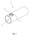
- Fig. 1 shows an embodiment of a suction pipe 1 for a vacuum cleaner, wherein the suction pipe 1 has a locking means which is formed by an insert 3 inserted into the pipe wall 2.
- the insert 3 is a - not shown - latching a - not shown - to be connected to the suction pipe neck element latched so that a positive connection between the neck element and the suction tube 1 is formed.
- the insert 3 is inserted into a breakthrough in the pipe wall 2, that no secondary air can penetrate into the suction channel 4 of the suction pipe 1 through the insert 3 or the opening, wherein the unit of locking means and pipe wall 2 form a closed surface.
- Fig. 2 shows a side view of the embodiment according to Fig. 1 in a sectioned side view.
- the insert 3 is adapted by rounding to the outer contour of the suction tube 1, that the mounted insert 3 does not protrude beyond the outer contour of the suction tube 1 and the insert 3 is flush with the outer contour of the suction tube 1.
- fastening means 5 which are formed in this embodiment as locking strips and co-operate with formed in the pipe wall 2 paragraphs 6 such that a positive connection between the insert 3 and pipe wall 2 and Saugrohr. 1 is trained.
- inlet bevels 8 are formed in this embodiment at the opposite in Saugrohrlnaturescardi transverse edges, which allow a simple sliding in and Hinausgl feasible the locking lug during unlocking and locking process.
- the insert 3 has a correspondingly sharp contour, so that a secure positive connection between locking lug and suction tube 1 is ensured.
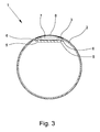
- Fig. 3 shows a section through the suction pipe 1 according to the Fig. 1 and 2 along the section line III in Fig. 2 ,
- the rounding of the insert 3 can be clearly seen here, so that the insert 3 inserted into the aperture in the tube wall 2 does not protrude beyond the outer contour of the tube 1 and terminates flush with the outer contour of the tube wall.
- the insert 3 is designed such that it reduces the flow cross-section of the suction pipe 1 only to a small extent and does not hinder the flow or elements entrained in the air flow can not tilt on the insert 3.
- the paragraph 6 is formed from the tube wall 2 and made by plastic deformation of the tube wall 2 in the suction pipe 1 and the flow cross-section.
- the insert 3 is supported on the shoulder 6 and is positively connected by means of the fastening means 5 with the shoulder 6, so that the insert is held firmly in the pipe wall 2.
- Fig. 4 shows an insert 3.
- the insert 3 is manufactured as an injection molded part from a plastic.
- the transverse edges 7 allow a secure locking of the locking lug of the lug element with the insert 3, wherein the inlet slopes 8 allow a quiet and comfortable sliding in and out of the detent.
- the recess 9 within the insert 3 has a substantially square base surface, so that two transverse edges 7 each extending transversely to the longitudinal extent of the suction tube 1 are formed.
- Fig. 5 shows the embodiment of the insert according to Fig. 4 in a sectional view.
- the insert 3 has - in this embodiment - circumferential fastening means 5, which are designed here as locking strips.
- the locking strips engage behind - as in Fig. 2 represented - the paragraph 6 of the pipe wall 2, so that a reliable connection between insert 3 and suction tube 1 is made.
- Fig. 5 is also the rounding of the insert 3 can be seen, which ensures an adaptation to the outer contour of the suction tube 1, so that the insert 3 does not protrude beyond the outer contour of the suction tube 1.
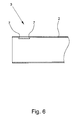
- Fig. 6 shows an embodiment of a suction tube 1 with a locking means which is formed as a recess in the tube wall 2.
- the return has In this embodiment, a square base, so that two transverse edges 7 are formed, which ensure a sharp contour of the locking means and allow a reliable connection with the locking lug of a connection element.
- the return is made by a deep-drawing process.
Landscapes
- Engineering & Computer Science (AREA)
- Mechanical Engineering (AREA)
- Electric Vacuum Cleaner (AREA)
Applications Claiming Priority (1)
| Application Number | Priority Date | Filing Date | Title |
|---|---|---|---|
| DE200910054162 DE102009054162B4 (de) | 2009-11-23 | 2009-11-23 | Saugrohr für einen Staubsauger |
Publications (3)
| Publication Number | Publication Date |
|---|---|
| EP2324749A2 true EP2324749A2 (fr) | 2011-05-25 |
| EP2324749A3 EP2324749A3 (fr) | 2013-11-06 |
| EP2324749B1 EP2324749B1 (fr) | 2015-03-04 |
Family
ID=43501156
Family Applications (1)
| Application Number | Title | Priority Date | Filing Date |
|---|---|---|---|
| EP20100014548 Not-in-force EP2324749B1 (fr) | 2009-11-23 | 2010-11-12 | Tuyau d'aspiration pour un aspirateur |
Country Status (2)
| Country | Link |
|---|---|
| EP (1) | EP2324749B1 (fr) |
| DE (1) | DE102009054162B4 (fr) |
Cited By (1)
| Publication number | Priority date | Publication date | Assignee | Title |
|---|---|---|---|---|
| EP2772174A3 (fr) * | 2013-03-01 | 2017-03-22 | Fischer Rohrtechnik GmbH | Tuyau d'aspiration pour aspirateur |
Family Cites Families (7)
| Publication number | Priority date | Publication date | Assignee | Title |
|---|---|---|---|---|
| NL301377A (fr) * | 1963-12-04 | |||
| FR1422372A (fr) * | 1964-11-10 | 1965-12-24 | Paris & Du Rhone | Système d'assemblage pour éléments d'appareils ménagers, et notamment pour manches, poignées ou accessoires d'aspirateurs |
| DE9213813U1 (de) * | 1992-10-13 | 1994-02-10 | Siemens AG, 80333 München | Rohrverbindung |
| DE10030304A1 (de) * | 2000-06-27 | 2002-02-14 | Froh House Tech Gmbh & Co Kg | Steckverbindbare Staubsaugerrohr-Anordnung |
| DE10059052A1 (de) * | 2000-11-28 | 2002-06-06 | Froh House Tech Gmbh & Co Kg | Teleskopierbares Staubsauger-Saugrohr |
| DE10120688A1 (de) * | 2001-04-27 | 2002-11-07 | Bsh Bosch Siemens Hausgeraete | Rohrverbindung für ein Saugrohr eines Staubsaugers |
| DE202004000425U1 (de) * | 2004-01-14 | 2004-04-15 | Fischer-Rohrtechnik Gmbh | Teleskopierbares Staubsauger-Saugrohr mit Ableitung der elektrostatischen Aufladung |
-
2009
- 2009-11-23 DE DE200910054162 patent/DE102009054162B4/de not_active Expired - Fee Related
-
2010
- 2010-11-12 EP EP20100014548 patent/EP2324749B1/fr not_active Not-in-force
Non-Patent Citations (1)
| Title |
|---|
| None |
Cited By (1)
| Publication number | Priority date | Publication date | Assignee | Title |
|---|---|---|---|---|
| EP2772174A3 (fr) * | 2013-03-01 | 2017-03-22 | Fischer Rohrtechnik GmbH | Tuyau d'aspiration pour aspirateur |
Also Published As
| Publication number | Publication date |
|---|---|
| EP2324749B1 (fr) | 2015-03-04 |
| EP2324749A3 (fr) | 2013-11-06 |
| DE102009054162A1 (de) | 2011-06-01 |
| DE102009054162B4 (de) | 2011-11-10 |
Similar Documents
| Publication | Publication Date | Title |
|---|---|---|
| EP3542086B1 (fr) | Filtre d'aspiration d'huile pour transmission ou moteur à combustion interne | |
| DE2703528B2 (de) | Wasserkühler, insbesondere für eine Brennkraftmaschine | |
| AT510774A1 (de) | Befestigungsvorrichtung für wandteile | |
| DE102017108433A1 (de) | Halterahmen für einen Steckverbinder und Verfahren zur Bestückung | |
| EP2057037B1 (fr) | Dispositif de retenue d'une baguette dans un canal | |
| DE102011005140A1 (de) | Rasteinrichtung für ein Pumpengehäuse und Pumpe | |
| DE2719820C2 (fr) | ||
| EP2592283B1 (fr) | Connecteur pour meuble | |
| DE202013010931U1 (de) | Verbindung zweier Teile | |
| EP3026350B1 (fr) | Hotte aspirante dotée d'un composant | |
| EP3392097B1 (fr) | Dispositif essuie-glaces | |
| DE102009054162B4 (de) | Saugrohr für einen Staubsauger | |
| DE9001715U1 (de) | Abschlußstück für eine Wandanschlußprofilleiste | |
| EP1587195B1 (fr) | Système de canalisation pour câble | |
| DE102012104918A1 (de) | Steckverbindung | |
| EP2660411B1 (fr) | Habillage de tête de clé | |
| DE102013201988B4 (de) | Befestigungsanordnung zur Anbringung eines Geräts, insbesondere eines Fahrzeugheizgeräts, an einer Trägerstruktur | |
| DE202008006607U1 (de) | Rückwandverbinder und Möbel | |
| EP2772174A2 (fr) | Tuyau d'aspiration pour aspirateur | |
| DE102010039454A1 (de) | Verschluss einer Befestigungsvorrichtung für ein Flächenelement einer Dunstabzugshaube und Dunstabzugshaube | |
| EP2498577A2 (fr) | Agencement pour un champ de cuisson ainsi que champ de cuisson à induction doté d'un agencement correspondant | |
| EP2821300B1 (fr) | Dispositif de raclette d'essuie-glace | |
| DE202007016892U1 (de) | Verbindungssystem für rinnenförmige Profilstäbe und Verbindungsanordnung | |
| EP2607825A2 (fr) | Combinaison d'appareils ménagers | |
| DE102005057589B4 (de) | Spannbügel |
Legal Events
| Date | Code | Title | Description |
|---|---|---|---|
| PUAI | Public reference made under article 153(3) epc to a published international application that has entered the european phase |
Free format text: ORIGINAL CODE: 0009012 |
|
| AK | Designated contracting states |
Kind code of ref document: A2 Designated state(s): AL AT BE BG CH CY CZ DE DK EE ES FI FR GB GR HR HU IE IS IT LI LT LU LV MC MK MT NL NO PL PT RO RS SE SI SK SM TR |
|
| AX | Request for extension of the european patent |
Extension state: BA ME |
|
| PUAL | Search report despatched |
Free format text: ORIGINAL CODE: 0009013 |
|
| AK | Designated contracting states |
Kind code of ref document: A3 Designated state(s): AL AT BE BG CH CY CZ DE DK EE ES FI FR GB GR HR HU IE IS IT LI LT LU LV MC MK MT NL NO PL PT RO RS SE SI SK SM TR |
|
| AX | Request for extension of the european patent |
Extension state: BA ME |
|
| RIC1 | Information provided on ipc code assigned before grant |
Ipc: A47L 9/00 20060101ALI20131002BHEP Ipc: A47L 9/24 20060101AFI20131002BHEP |
|
| 17P | Request for examination filed |
Effective date: 20140404 |
|
| RBV | Designated contracting states (corrected) |
Designated state(s): AL AT BE BG CH CY CZ DE DK EE ES FI FR GB GR HR HU IE IS IT LI LT LU LV MC MK MT NL NO PL PT RO RS SE SI SK SM TR |
|
| GRAP | Despatch of communication of intention to grant a patent |
Free format text: ORIGINAL CODE: EPIDOSNIGR1 |
|
| INTG | Intention to grant announced |
Effective date: 20141027 |
|
| GRAS | Grant fee paid |
Free format text: ORIGINAL CODE: EPIDOSNIGR3 |
|
| GRAA | (expected) grant |
Free format text: ORIGINAL CODE: 0009210 |
|
| AK | Designated contracting states |
Kind code of ref document: B1 Designated state(s): AL AT BE BG CH CY CZ DE DK EE ES FI FR GB GR HR HU IE IS IT LI LT LU LV MC MK MT NL NO PL PT RO RS SE SI SK SM TR |
|
| REG | Reference to a national code |
Ref country code: GB Ref legal event code: FG4D Free format text: NOT ENGLISH |
|
| REG | Reference to a national code |
Ref country code: CH Ref legal event code: EP |
|
| REG | Reference to a national code |
Ref country code: IE Ref legal event code: FG4D Free format text: LANGUAGE OF EP DOCUMENT: GERMAN |
|
| REG | Reference to a national code |
Ref country code: AT Ref legal event code: REF Ref document number: 713072 Country of ref document: AT Kind code of ref document: T Effective date: 20150415 |
|
| REG | Reference to a national code |
Ref country code: DE Ref legal event code: R096 Ref document number: 502010009028 Country of ref document: DE Effective date: 20150416 |
|
| REG | Reference to a national code |
Ref country code: NL Ref legal event code: T3 |
|
| PG25 | Lapsed in a contracting state [announced via postgrant information from national office to epo] |
Ref country code: SE Free format text: LAPSE BECAUSE OF FAILURE TO SUBMIT A TRANSLATION OF THE DESCRIPTION OR TO PAY THE FEE WITHIN THE PRESCRIBED TIME-LIMIT Effective date: 20150304 Ref country code: HR Free format text: LAPSE BECAUSE OF FAILURE TO SUBMIT A TRANSLATION OF THE DESCRIPTION OR TO PAY THE FEE WITHIN THE PRESCRIBED TIME-LIMIT Effective date: 20150304 Ref country code: FI Free format text: LAPSE BECAUSE OF FAILURE TO SUBMIT A TRANSLATION OF THE DESCRIPTION OR TO PAY THE FEE WITHIN THE PRESCRIBED TIME-LIMIT Effective date: 20150304 Ref country code: ES Free format text: LAPSE BECAUSE OF FAILURE TO SUBMIT A TRANSLATION OF THE DESCRIPTION OR TO PAY THE FEE WITHIN THE PRESCRIBED TIME-LIMIT Effective date: 20150304 Ref country code: NO Free format text: LAPSE BECAUSE OF FAILURE TO SUBMIT A TRANSLATION OF THE DESCRIPTION OR TO PAY THE FEE WITHIN THE PRESCRIBED TIME-LIMIT Effective date: 20150604 Ref country code: LT Free format text: LAPSE BECAUSE OF FAILURE TO SUBMIT A TRANSLATION OF THE DESCRIPTION OR TO PAY THE FEE WITHIN THE PRESCRIBED TIME-LIMIT Effective date: 20150304 |
|
| REG | Reference to a national code |
Ref country code: LT Ref legal event code: MG4D |
|
| PG25 | Lapsed in a contracting state [announced via postgrant information from national office to epo] |
Ref country code: RS Free format text: LAPSE BECAUSE OF FAILURE TO SUBMIT A TRANSLATION OF THE DESCRIPTION OR TO PAY THE FEE WITHIN THE PRESCRIBED TIME-LIMIT Effective date: 20150304 Ref country code: GR Free format text: LAPSE BECAUSE OF FAILURE TO SUBMIT A TRANSLATION OF THE DESCRIPTION OR TO PAY THE FEE WITHIN THE PRESCRIBED TIME-LIMIT Effective date: 20150605 Ref country code: LV Free format text: LAPSE BECAUSE OF FAILURE TO SUBMIT A TRANSLATION OF THE DESCRIPTION OR TO PAY THE FEE WITHIN THE PRESCRIBED TIME-LIMIT Effective date: 20150304 |
|
| PG25 | Lapsed in a contracting state [announced via postgrant information from national office to epo] |
Ref country code: RO Free format text: LAPSE BECAUSE OF FAILURE TO SUBMIT A TRANSLATION OF THE DESCRIPTION OR TO PAY THE FEE WITHIN THE PRESCRIBED TIME-LIMIT Effective date: 20150304 Ref country code: SK Free format text: LAPSE BECAUSE OF FAILURE TO SUBMIT A TRANSLATION OF THE DESCRIPTION OR TO PAY THE FEE WITHIN THE PRESCRIBED TIME-LIMIT Effective date: 20150304 Ref country code: CZ Free format text: LAPSE BECAUSE OF FAILURE TO SUBMIT A TRANSLATION OF THE DESCRIPTION OR TO PAY THE FEE WITHIN THE PRESCRIBED TIME-LIMIT Effective date: 20150304 Ref country code: PT Free format text: LAPSE BECAUSE OF FAILURE TO SUBMIT A TRANSLATION OF THE DESCRIPTION OR TO PAY THE FEE WITHIN THE PRESCRIBED TIME-LIMIT Effective date: 20150706 Ref country code: EE Free format text: LAPSE BECAUSE OF FAILURE TO SUBMIT A TRANSLATION OF THE DESCRIPTION OR TO PAY THE FEE WITHIN THE PRESCRIBED TIME-LIMIT Effective date: 20150304 |
|
| REG | Reference to a national code |
Ref country code: FR Ref legal event code: PLFP Year of fee payment: 6 |
|
| PG25 | Lapsed in a contracting state [announced via postgrant information from national office to epo] |
Ref country code: PL Free format text: LAPSE BECAUSE OF FAILURE TO SUBMIT A TRANSLATION OF THE DESCRIPTION OR TO PAY THE FEE WITHIN THE PRESCRIBED TIME-LIMIT Effective date: 20150304 Ref country code: IS Free format text: LAPSE BECAUSE OF FAILURE TO SUBMIT A TRANSLATION OF THE DESCRIPTION OR TO PAY THE FEE WITHIN THE PRESCRIBED TIME-LIMIT Effective date: 20150704 |
|
| REG | Reference to a national code |
Ref country code: DE Ref legal event code: R097 Ref document number: 502010009028 Country of ref document: DE |
|
| PLBE | No opposition filed within time limit |
Free format text: ORIGINAL CODE: 0009261 |
|
| STAA | Information on the status of an ep patent application or granted ep patent |
Free format text: STATUS: NO OPPOSITION FILED WITHIN TIME LIMIT |
|
| PG25 | Lapsed in a contracting state [announced via postgrant information from national office to epo] |
Ref country code: DK Free format text: LAPSE BECAUSE OF FAILURE TO SUBMIT A TRANSLATION OF THE DESCRIPTION OR TO PAY THE FEE WITHIN THE PRESCRIBED TIME-LIMIT Effective date: 20150304 |
|
| PGFP | Annual fee paid to national office [announced via postgrant information from national office to epo] |
Ref country code: LU Payment date: 20151119 Year of fee payment: 6 Ref country code: GB Payment date: 20151118 Year of fee payment: 6 Ref country code: IT Payment date: 20151125 Year of fee payment: 6 Ref country code: CH Payment date: 20151118 Year of fee payment: 6 |
|
| 26N | No opposition filed |
Effective date: 20151207 |
|
| PG25 | Lapsed in a contracting state [announced via postgrant information from national office to epo] |
Ref country code: SI Free format text: LAPSE BECAUSE OF FAILURE TO SUBMIT A TRANSLATION OF THE DESCRIPTION OR TO PAY THE FEE WITHIN THE PRESCRIBED TIME-LIMIT Effective date: 20150304 |
|
| PGFP | Annual fee paid to national office [announced via postgrant information from national office to epo] |
Ref country code: AT Payment date: 20151119 Year of fee payment: 6 Ref country code: NL Payment date: 20151118 Year of fee payment: 6 Ref country code: BE Payment date: 20151118 Year of fee payment: 6 Ref country code: FR Payment date: 20151119 Year of fee payment: 6 |
|
| PGFP | Annual fee paid to national office [announced via postgrant information from national office to epo] |
Ref country code: DE Payment date: 20160126 Year of fee payment: 6 |
|
| PG25 | Lapsed in a contracting state [announced via postgrant information from national office to epo] |
Ref country code: MC Free format text: LAPSE BECAUSE OF FAILURE TO SUBMIT A TRANSLATION OF THE DESCRIPTION OR TO PAY THE FEE WITHIN THE PRESCRIBED TIME-LIMIT Effective date: 20150304 |
|
| REG | Reference to a national code |
Ref country code: IE Ref legal event code: MM4A |
|
| PG25 | Lapsed in a contracting state [announced via postgrant information from national office to epo] |
Ref country code: IE Free format text: LAPSE BECAUSE OF NON-PAYMENT OF DUE FEES Effective date: 20151112 |
|
| PG25 | Lapsed in a contracting state [announced via postgrant information from national office to epo] |
Ref country code: BE Free format text: LAPSE BECAUSE OF NON-PAYMENT OF DUE FEES Effective date: 20161130 |
|
| PG25 | Lapsed in a contracting state [announced via postgrant information from national office to epo] |
Ref country code: BG Free format text: LAPSE BECAUSE OF FAILURE TO SUBMIT A TRANSLATION OF THE DESCRIPTION OR TO PAY THE FEE WITHIN THE PRESCRIBED TIME-LIMIT Effective date: 20150304 Ref country code: SM Free format text: LAPSE BECAUSE OF FAILURE TO SUBMIT A TRANSLATION OF THE DESCRIPTION OR TO PAY THE FEE WITHIN THE PRESCRIBED TIME-LIMIT Effective date: 20150304 Ref country code: HU Free format text: LAPSE BECAUSE OF FAILURE TO SUBMIT A TRANSLATION OF THE DESCRIPTION OR TO PAY THE FEE WITHIN THE PRESCRIBED TIME-LIMIT; INVALID AB INITIO Effective date: 20101112 |
|
| REG | Reference to a national code |
Ref country code: DE Ref legal event code: R119 Ref document number: 502010009028 Country of ref document: DE |
|
| PG25 | Lapsed in a contracting state [announced via postgrant information from national office to epo] |
Ref country code: CY Free format text: LAPSE BECAUSE OF FAILURE TO SUBMIT A TRANSLATION OF THE DESCRIPTION OR TO PAY THE FEE WITHIN THE PRESCRIBED TIME-LIMIT Effective date: 20150304 |
|
| REG | Reference to a national code |
Ref country code: CH Ref legal event code: PL |
|
| REG | Reference to a national code |
Ref country code: NL Ref legal event code: MM Effective date: 20161201 |
|
| REG | Reference to a national code |
Ref country code: AT Ref legal event code: MM01 Ref document number: 713072 Country of ref document: AT Kind code of ref document: T Effective date: 20161112 |
|
| GBPC | Gb: european patent ceased through non-payment of renewal fee |
Effective date: 20161112 |
|
| PG25 | Lapsed in a contracting state [announced via postgrant information from national office to epo] |
Ref country code: CH Free format text: LAPSE BECAUSE OF NON-PAYMENT OF DUE FEES Effective date: 20161130 Ref country code: LI Free format text: LAPSE BECAUSE OF NON-PAYMENT OF DUE FEES Effective date: 20161130 |
|
| REG | Reference to a national code |
Ref country code: FR Ref legal event code: ST Effective date: 20170731 |
|
| PG25 | Lapsed in a contracting state [announced via postgrant information from national office to epo] |
Ref country code: MT Free format text: LAPSE BECAUSE OF FAILURE TO SUBMIT A TRANSLATION OF THE DESCRIPTION OR TO PAY THE FEE WITHIN THE PRESCRIBED TIME-LIMIT Effective date: 20150304 Ref country code: AT Free format text: LAPSE BECAUSE OF NON-PAYMENT OF DUE FEES Effective date: 20161112 Ref country code: TR Free format text: LAPSE BECAUSE OF FAILURE TO SUBMIT A TRANSLATION OF THE DESCRIPTION OR TO PAY THE FEE WITHIN THE PRESCRIBED TIME-LIMIT Effective date: 20150304 |
|
| PG25 | Lapsed in a contracting state [announced via postgrant information from national office to epo] |
Ref country code: NL Free format text: LAPSE BECAUSE OF NON-PAYMENT OF DUE FEES Effective date: 20161201 Ref country code: LU Free format text: LAPSE BECAUSE OF NON-PAYMENT OF DUE FEES Effective date: 20161130 |
|
| PG25 | Lapsed in a contracting state [announced via postgrant information from national office to epo] |
Ref country code: IT Free format text: LAPSE BECAUSE OF NON-PAYMENT OF DUE FEES Effective date: 20161112 Ref country code: FR Free format text: LAPSE BECAUSE OF NON-PAYMENT OF DUE FEES Effective date: 20161130 |
|
| PG25 | Lapsed in a contracting state [announced via postgrant information from national office to epo] |
Ref country code: GB Free format text: LAPSE BECAUSE OF NON-PAYMENT OF DUE FEES Effective date: 20161112 Ref country code: DE Free format text: LAPSE BECAUSE OF NON-PAYMENT OF DUE FEES Effective date: 20170601 |
|
| REG | Reference to a national code |
Ref country code: BE Ref legal event code: MM Effective date: 20161130 |
|
| PG25 | Lapsed in a contracting state [announced via postgrant information from national office to epo] |
Ref country code: MK Free format text: LAPSE BECAUSE OF FAILURE TO SUBMIT A TRANSLATION OF THE DESCRIPTION OR TO PAY THE FEE WITHIN THE PRESCRIBED TIME-LIMIT Effective date: 20150304 |
|
| PG25 | Lapsed in a contracting state [announced via postgrant information from national office to epo] |
Ref country code: AL Free format text: LAPSE BECAUSE OF FAILURE TO SUBMIT A TRANSLATION OF THE DESCRIPTION OR TO PAY THE FEE WITHIN THE PRESCRIBED TIME-LIMIT Effective date: 20150304 |