EP2324788B1 - Vorrichtungen zur Abgabe elektromagnetischer Energie, die eine Energieapplikatoranordnung enthalten, und elektrochirurgische Systeme, die diese Vorrichtungen enthalten - Google Patents
Vorrichtungen zur Abgabe elektromagnetischer Energie, die eine Energieapplikatoranordnung enthalten, und elektrochirurgische Systeme, die diese Vorrichtungen enthalten Download PDFInfo
- Publication number
- EP2324788B1 EP2324788B1 EP10014705.7A EP10014705A EP2324788B1 EP 2324788 B1 EP2324788 B1 EP 2324788B1 EP 10014705 A EP10014705 A EP 10014705A EP 2324788 B1 EP2324788 B1 EP 2324788B1
- Authority
- EP
- European Patent Office
- Prior art keywords
- electrically
- energy
- electrosurgical system
- assembly
- conductive
- Prior art date
- Legal status (The legal status is an assumption and is not a legal conclusion. Google has not performed a legal analysis and makes no representation as to the accuracy of the status listed.)
- Active
Links
Images





Classifications
-
- A—HUMAN NECESSITIES
- A61—MEDICAL OR VETERINARY SCIENCE; HYGIENE
- A61B—DIAGNOSIS; SURGERY; IDENTIFICATION
- A61B18/00—Surgical instruments, devices or methods for transferring non-mechanical forms of energy to or from the body
- A61B18/18—Surgical instruments, devices or methods for transferring non-mechanical forms of energy to or from the body by applying electromagnetic radiation, e.g. microwaves
- A61B18/1815—Surgical instruments, devices or methods for transferring non-mechanical forms of energy to or from the body by applying electromagnetic radiation, e.g. microwaves using microwaves
-
- H—ELECTRICITY
- H01—ELECTRIC ELEMENTS
- H01R—ELECTRICALLY-CONDUCTIVE CONNECTIONS; STRUCTURAL ASSOCIATIONS OF A PLURALITY OF MUTUALLY-INSULATED ELECTRICAL CONNECTING ELEMENTS; COUPLING DEVICES; CURRENT COLLECTORS
- H01R43/00—Apparatus or processes specially adapted for manufacturing, assembling, maintaining, or repairing of line connectors or current collectors or for joining electric conductors
-
- A—HUMAN NECESSITIES
- A61—MEDICAL OR VETERINARY SCIENCE; HYGIENE
- A61B—DIAGNOSIS; SURGERY; IDENTIFICATION
- A61B18/00—Surgical instruments, devices or methods for transferring non-mechanical forms of energy to or from the body
- A61B2018/00005—Cooling or heating of the probe or tissue immediately surrounding the probe
- A61B2018/00011—Cooling or heating of the probe or tissue immediately surrounding the probe with fluids
- A61B2018/00023—Cooling or heating of the probe or tissue immediately surrounding the probe with fluids closed, i.e. without wound contact by the fluid
-
- A—HUMAN NECESSITIES
- A61—MEDICAL OR VETERINARY SCIENCE; HYGIENE
- A61B—DIAGNOSIS; SURGERY; IDENTIFICATION
- A61B18/00—Surgical instruments, devices or methods for transferring non-mechanical forms of energy to or from the body
- A61B2018/00571—Surgical instruments, devices or methods for transferring non-mechanical forms of energy to or from the body for achieving a particular surgical effect
- A61B2018/00577—Ablation
-
- A—HUMAN NECESSITIES
- A61—MEDICAL OR VETERINARY SCIENCE; HYGIENE
- A61B—DIAGNOSIS; SURGERY; IDENTIFICATION
- A61B18/00—Surgical instruments, devices or methods for transferring non-mechanical forms of energy to or from the body
- A61B2018/00636—Sensing and controlling the application of energy
- A61B2018/00696—Controlled or regulated parameters
- A61B2018/00732—Frequency
-
- A—HUMAN NECESSITIES
- A61—MEDICAL OR VETERINARY SCIENCE; HYGIENE
- A61B—DIAGNOSIS; SURGERY; IDENTIFICATION
- A61B18/00—Surgical instruments, devices or methods for transferring non-mechanical forms of energy to or from the body
- A61B2018/00636—Sensing and controlling the application of energy
- A61B2018/00696—Controlled or regulated parameters
- A61B2018/0075—Phase
-
- A—HUMAN NECESSITIES
- A61—MEDICAL OR VETERINARY SCIENCE; HYGIENE
- A61B—DIAGNOSIS; SURGERY; IDENTIFICATION
- A61B18/00—Surgical instruments, devices or methods for transferring non-mechanical forms of energy to or from the body
- A61B18/18—Surgical instruments, devices or methods for transferring non-mechanical forms of energy to or from the body by applying electromagnetic radiation, e.g. microwaves
- A61B18/1815—Surgical instruments, devices or methods for transferring non-mechanical forms of energy to or from the body by applying electromagnetic radiation, e.g. microwaves using microwaves
- A61B2018/183—Surgical instruments, devices or methods for transferring non-mechanical forms of energy to or from the body by applying electromagnetic radiation, e.g. microwaves using microwaves characterised by the type of antenna
-
- A—HUMAN NECESSITIES
- A61—MEDICAL OR VETERINARY SCIENCE; HYGIENE
- A61B—DIAGNOSIS; SURGERY; IDENTIFICATION
- A61B18/00—Surgical instruments, devices or methods for transferring non-mechanical forms of energy to or from the body
- A61B18/18—Surgical instruments, devices or methods for transferring non-mechanical forms of energy to or from the body by applying electromagnetic radiation, e.g. microwaves
- A61B18/1815—Surgical instruments, devices or methods for transferring non-mechanical forms of energy to or from the body by applying electromagnetic radiation, e.g. microwaves using microwaves
- A61B2018/183—Surgical instruments, devices or methods for transferring non-mechanical forms of energy to or from the body by applying electromagnetic radiation, e.g. microwaves using microwaves characterised by the type of antenna
- A61B2018/1838—Dipole antennas
-
- Y—GENERAL TAGGING OF NEW TECHNOLOGICAL DEVELOPMENTS; GENERAL TAGGING OF CROSS-SECTIONAL TECHNOLOGIES SPANNING OVER SEVERAL SECTIONS OF THE IPC; TECHNICAL SUBJECTS COVERED BY FORMER USPC CROSS-REFERENCE ART COLLECTIONS [XRACs] AND DIGESTS
- Y10—TECHNICAL SUBJECTS COVERED BY FORMER USPC
- Y10T—TECHNICAL SUBJECTS COVERED BY FORMER US CLASSIFICATION
- Y10T29/00—Metal working
- Y10T29/49—Method of mechanical manufacture
- Y10T29/49002—Electrical device making
- Y10T29/49016—Antenna or wave energy "plumbing" making
- Y10T29/49018—Antenna or wave energy "plumbing" making with other electrical component
-
- Y—GENERAL TAGGING OF NEW TECHNOLOGICAL DEVELOPMENTS; GENERAL TAGGING OF CROSS-SECTIONAL TECHNOLOGIES SPANNING OVER SEVERAL SECTIONS OF THE IPC; TECHNICAL SUBJECTS COVERED BY FORMER USPC CROSS-REFERENCE ART COLLECTIONS [XRACs] AND DIGESTS
- Y10—TECHNICAL SUBJECTS COVERED BY FORMER USPC
- Y10T—TECHNICAL SUBJECTS COVERED BY FORMER US CLASSIFICATION
- Y10T29/00—Metal working
- Y10T29/49—Method of mechanical manufacture
- Y10T29/49002—Electrical device making
- Y10T29/49117—Conductor or circuit manufacturing
Definitions
- the present disclosure relates to electrosurgical devices suitable for use in surface ablation applications and, more particularly, to electromagnetic energy delivery devices including an energy applicator array and electrosurgical systems including the same.
- Electromagnetic radiation can be used to heat and destroy tumor cells. Treatment may involve inserting ablation probes into tissues where cancerous tumors have been identified. Once the probes are positioned, electromagnetic energy is passed through the probes into surrounding tissue.
- microwave apparatus for use in ablation procedures include a microwave generator that functions as an energy source, and a microwave surgical instrument (e.g., microwave ablation probe) having an antenna assembly for directing the energy to the target tissue.
- the microwave generator and surgical instrument are typically operatively coupled by a cable assembly having a plurality of conductors for transmitting microwave energy from the generator to the instrument, and for communicating control, feedback and identification signals between the instrument and the generator.
- monopole and dipole antenna assemblies microwave energy generally radiates perpendicularly away from the axis of the conductor.
- Monopole antenna assemblies typically include a single, elongated conductor.
- a typical dipole antenna assembly includes two elongated conductors that are linearly aligned and positioned end-to-end relative to one another with an electrical insulator placed therebetween.
- Helical antenna assemblies include helically-shaped conductor configurations of various dimensions, e.g., diameter and length.
- the main modes of operation of a helical antenna assembly are normal mode (broadside), in which the field radiated by the helix is maximum in a perpendicular plane to the helix axis, and axial mode (end fire), in which maximum radiation is along the helix axis.
- a microwave transmission line typically includes a long, thin inner conductor that extends along the longitudinal axis of the transmission line and is surrounded by a dielectric material and is further surrounded by an outer conductor around the dielectric material such that the outer conductor also extends along the transmission line axis.
- a waveguiding structure such as a length of transmission line or coaxial cable, is provided with a plurality of openings through which energy "leaks" or radiates away from the guiding structure. This type of construction is typically referred to as a “leaky coaxial” or “leaky wave” antenna.
- the design of the microwave applicator radiating antenna(s) influences the thermal distribution.
- Electric power is generally measured in watts (W), or joules per second.
- the overall heating pattern produced by the multiple applicators may be a combination of the individual heating patterns produced by each separate applicator, or a result of the super-position of electromagnetic waves from all the applicators in the system.
- WO 2009/128940 A1 discloses systems, apparatus, methods and procedures for the non-invasive treatment of tissue,including treatment using microwave energy.
- a medical device and associated apparatus and procedures are used to treat dermatological conditions using, for example, microwave energy.
- WO 2008/012827 A2 discloses devices including one or more electromagnetic RF generating units, multiple RF electrode groups and a controller for controllably applying RF energy to the skin through any selected RF electrode group or any selected RF electrode group combination selected from the multiple groups.
- the electrodes may be stationary and/or movable electrodes.
- the present disclosure relates to an electrosurgical system for directing energy to tissue including a generator assembly operable to supply power having a selected phase, amplitude and frequency,and an applicator array assembly.
- the applicator array assembly includes a shell assembly, a plurality of energy applicators disposed within the shell assembly, and a power divider unit electrically coupled to the generator assembly.
- the power divider unit is operable to divide power into the applicator array assembly.
- Described herein is a method for manufacturing an electrosurgical device including the initial steps of: providing a plurality of coaxial cables, each having an inner conductor, an outer conductor, and a dielectric material disposed there between; forming a plurality of first applicator segments by joining an electrically-conductive member to a distal end of the inner conductor of each of the plurality of coaxial cables; forming a plurality of second applicator segments by joining a balun structure to a distal portion of the outer conductor of each of the plurality of first applicator segments; forming a plurality of third applicator segments by positioning an electrically-conductive cylinder overlying a distal portion of the balun structure of each of the plurality of second applicator segments.
- the method also includes the step of forming a plurality of energy applicators by forming a dielectric structure having a proximal end disposed substantially adjacent to a distal end of the electrically-conductive cylinder of each of the plurality of third applicator segments. Each dielectric structure longitudinally extends from the distal end of the electrically-conductive cylinder to a distal end of the electrically-conductive member.
- the method also includes the steps of forming an applicator array assembly including the plurality of energy applicators and having a chamber disposed at least partially surrounding the plurality of energy applicators configured for circulating coolant fluid thereabout,and providing a power divider unit configured for dividing power for a plurality of channels connected to the applicator array assembly.
- proximal refers to that portion of the apparatus that is closer to the user and the term “distal” refers to that portion of the apparatus that is farther from the user.
- a phrase in the form "A/B” means A or B.
- a phrase in the form "A and/or B” means "(A),(B), or (A and B)”.
- a phrase in the form "at least one of A, B, or C” means "(A), (B), (C),(A and B), (A and C), (Band C), or (A, B and C)”.
- Electromagnetic energy is generally classified by increasing energy or decreasing wavelength into radio waves, microwaves, infrared, visible light, ultraviolet, X-rays and gamma-rays.
- microwave generally refers to electromagnetic waves in the frequency range of 300 megahertz (MHz) (3 x 10 8 cycles/second) to 300 gigahertz (GHz) (3 x 10 11 cycles/second).
- ablation procedure generally refers to any ablation procedure, such as microwave ablation, radio frequency (RF) ablation or microwave ablation assisted resection.
- transmission line generally refers to any transmission medium that can be used for the propagation of signals from one point to another.
- length may refer to electrical length or physical length.
- electrical length is an expression of the length of a transmission medium in terms of the wavelength of a signal propagating within the medium. Electrical length is normally expressed in terms of wavelength, radians or degrees.
- electrical length may be expressed as a multiple or sub-multiple of the wavelength of an electromagnetic wave or electrical signal propagating within a transmission medium.
- the wavelength may be expressed in radians or in artificial units of angular measure,such as degrees.
- the electric length of a transmission medium may be expressed as its physical length multiplied by the ratio of (a) the propagation time of an electrical or electromagnetic signal through the medium to (b) the propagation time of an electromagnetic wave in free space over a distance equal to the physical length of the medium.
- the electrical length is in general different from the physical length. By the addition of an appropriate reactive element (capacitive or inductive), the electrical length may be made significantly shorter or longer than the physical length.
- the present disclosure provides electromagnetic energy delivery devices for treating tissue and methods of directing electromagnetic radiation to tissue. These may be implemented using electromagnetic radiation at microwave frequencies or at other frequencies.
- An electromagnetic energy delivery device including an energy applicator array is designed and configured to operate between about 500 MHz and about 10 GHz with a directional radiation pattern.
- the presently disclosed electromagnetic energy delivery device includes an energy applicator array suitable for microwave ablation and for use to pre-coagulate tissue for microwave ablation assisted surgical resection.
- an energy applicator array suitable for microwave ablation and for use to pre-coagulate tissue for microwave ablation assisted surgical resection.
- various methods described hereinbelow are targeted toward microwave ablation and the complete destruction of target tissue, it is to be understood that methods for directing electromagnetic radiation may be used with other therapies in which the target tissue is partially destroyed or damaged, such as, for example, to prevent the conduction of electrical impulses within heart tissue.
- the teachings of the present disclosure may also apply to a monopole, helical, or other suitable type of microwave antenna.
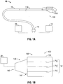
- FIG. 1A shows an electrosurgical system 10 that includes an electromagnetic energy delivery device or ablation array assembly 100.
- An electromagnetic energy delivery device such as the ablation array assembly 100 of FIG. 1A , in accordance with the present disclosure,is shown in more detail in FIGS. 9 through 11 . It will be understood, however, that other electromagnetic energy delivery device embodiments may also be used.
- Ablation array assembly 100 which is described in more detail later in this disclosure, generally includes an energy applicator array 810 having a radiating portion connected by a feedline 110 (or shaft) via a transmission line 15 to a connector 16, which may further operably connect the ablation array assembly 100 to a power generating source or generator assembly 28, e.g., a microwave or RF electrosurgical generator.
- a power generating source or generator assembly 28 e.g., a microwave or RF electrosurgical generator.
- Feedline 110 may be formed from a suitable flexible, semi-rigid or rigid microwave conductive cable and may connect directly to an electrosurgical power generating source 28. Alternatively, the feedline 110 may electrically connect the energy applicator array 810 via the transmission line 15 to the electrosurgical power generating source 28. Feedline 110 may have a variable length from a proximal end of the energy applicator array 810 to a distal end of transmission line 15 ranging from a length of about one inch (25.44mm) to about twelve inches (30.48mm). Feedline 110 may be formed of suitable electrically-conductive materials, e.g., copper, gold, silver or other conductive metals or metal alloys having similar conductivity values.
- suitable electrically-conductive materials e.g., copper, gold, silver or other conductive metals or metal alloys having similar conductivity values.
- Feedline 110 may be made of stainless steel, which generally offers the strength required to puncture tissue and/or skin. Conductive materials used to form the feedline 110 may be plated with other materials, e.g., other conductive materials, such as gold or silver, to improve their properties, e.g. to improve conductivity, decrease energy loss, etc.
- the feedline 110 includes stainless steel, and to improve the conductivity thereof, the stainless steel may be coated with a layer of a conductive material such as copper or gold.
- Feedline 110 may include an inner conductor, a dielectric material coaxially surrounding the inner conductor, and an outer conductor coaxially surrounding the dielectric material. Feedline 110 may be cooled by fluid e.g., saline or water, to improve power handling, and may include a stainless steel catheter.
- the power generating source 28 is configured to provide microwave energy at an operational frequency from about 500 MHz to about 2500 MHz. Another power generating source 28 is configured to provide microwave energy at an operational frequency from about 500 MHz to about 10 GHz. Power generating source 28 may be configured to provide various frequencies of electromagnetic energy.
- Transmission line 15 may additionally, or alternatively, provide a conduit (not shown) configured to provide coolant fluid from a coolant source 18 to one or more components of the ablation array assembly 100.
- the ablation array assembly 100 may be provided with a coolant chamber (e.g., 1060 shown in FIG. 10 ). Additionally, the ablation array assembly 100 may include coolant inflow and outflow ports (not shown) to facilitate the flow of coolant into,and out of, the coolant chamber. Examples of coolant chamber and coolant inflow and outflow ports are disclosed in commonly assigned U.S. Patent Application Serial No. 12/401,268 filed on March 10, 2009 , entitled “COOLED DIELECTRICALLY BUFFERED MICROWAVE DIPOLE ANTENNA",and U.S. Pat. No. 7,311,703 ,entitled “DEVICES AND METHODS FOR COOLING MICROWAVE ANTENNAS".
- the electromagnetic energy delivery device 100 is inserted into or placed adjacent to tissue and microwave energy is supplied thereto.
- Ultrasound or computed tomography (CT) guidance may be used to accurately guide the ablation array assembly 100 into the area of tissue to be treated.
- Ablation array assembly 100 may be placed percutaneously or surgically, e.g., using conventional surgical techniques by surgical staff. A clinician may pre-determine the length of time that microwave energy is to be applied. Application duration may depend on many factors such as tumor size and location and whether the tumor was a secondary or primary cancer. The duration of microwave energy application using the ablation array assembly 100 may depend on the progress of the heat distribution within the tissue area that is to be destroyed and/or the surrounding tissue.
- Single or multiple electromagnetic energy delivery devices 100 may provide ablations in short procedure times, e.g., a few minutes, to destroy cancerous cells in the target tissue region.
- a plurality of electromagnetic energy delivery devices 100 may be placed in variously-arranged configurations to substantially simultaneously ablate a target tissue region, making faster procedures possible. Multiple electromagnetic energy delivery devices 100 can be used to synergistically create a large ablation or to ablate separate sites simultaneously. Tissue ablation size and geometry is Influenced by a variety of factors, such as the energy applicator design, number of energy applicators used simultaneously, ablation time and wattage, and tissue characteristics.
- FIG. 1B schematically shows an electromagnetic energy delivery device 100 of the electrosurgical system 10 of FIG. 1A that includes an applicator array assembly 150, a generator assembly 28 that supplies power having a selected phase, amplitude and frequency, and a power divider unit 140 electrically coupled to the generator assembly 28 that divides power into the applicator array assembly 150.
- Power divider unit 140 generally divides power into a plurality of energy applicators (e.g., 270A, 270B, 270C shown in FIG. 19 ) of the applicator array assembly 150.
- the applicator array assembly 150 and the power divider unit 140 are integrally formed.
- the applicator array assembly 150 includes a shell assembly 155 and an applicator array "A” that may include any “N” number of energy applicators (e.g., “A 1 " "A 2 ",!A N "), and may include a cooling chamber (e.g., 1060 shown in FIG. 10 ). Because of constructive interference of electric fields at the intended focus and destructive interference of electric fields away from the focus,geometrically-focused energy deposition from multiple electric fields emitted from the applicator array assembly 150,according to the present disclosure, may improve localization of the absorbed energy in targeted tissue and focus heat reliably.
- Power divider unit 140 generally divides power for a plurality of channels (e.g., 350A, 350B, 350C shown in FIG. 20 ) connected to the applicator array assembly 150, and may include a plurality of output ports (e.g., 448A, 448B, 448C shown in FIG. 21 ), wherein each output port may be connectable to any one or more of the energy applicators of the applicator array assembly 150.
- the power divider unit 140 may include a plurality of phase shifters (e.g., 443A, 443B, 443C shown in FIG. 21 ).
- the power divider unit 140 includes a phase-balanced microwave power splitter (e.g., 240 shown in FIG.
- a generator assembly (e.g., 28 shown in FIG. 1B ) includes a processor (e.g., 82 shown in FIG. 17 ) that is operably coupled to one or more phase monitor units (e.g., 447A, 447B, 447C shown in FIG. 21 ) of the power divider unit 140.
- phase monitor units e.g., 447A, 447B, 447C shown in FIG. 21
- Power divider unit 140 may be a power splitter configured to split an input signal from the generator assembly 28 into two or more equal phase output signals,such as a Wilkinson power splitter.
- Power divider unit 140 may be implemented by any suitable power divider that provides equal or unequal power split at the output ports of the power divider unit 140.
- Power divider unit 140 may maintain phase and/or amplitude balance.
- the power divider unit 140 may be implemented using a 2-way power divider that provides equal or unequal power split at its output ports while maintaining a phase balance of ⁇ +/-45 degrees.
- the power divider unit 140 may include a controller (e.g., 330 shown in FIG.21 ).
- Powerdivider unit 140 may deliver microwave power to particular channels individually or any combination of one or more channels equally or unequally to facilitate selective activation of energy delivery to particular channels or combination of channels. For example, a user may select channels to which energy is delivered. In this scenario, if the second and third channels are selected,energy delivery may be divided equally between the second and third channels and, thus, unequally between the first channel and the second and third channels since no energy is delivered to the first channel in this scenario. Further, in this scenario, energy may be delivered to individual channels according to selected time intervals by dynamically changing the channels to which energy is delivered. For example, energy may be delivered to the first channel at a time interval. At a subsequent time interval, t2,energy is delivered to the first channel and the third channel.
- the power divider unit 140 may divide energy between the energy applicators (e.g., "A 1 ", “A 2 “, “A N “ shown in FIG. 1B ) to tailor the size and shape of ablation lesions.
- Applicator array assembly 150 includes a plurality of input ports (not shown) connectable to any one or more output ports (not shown) of the power divider unit 140, and may be disposed substantially adjacent to a distal end portion 141 of the power divider unit 140.
- a handle assembly (not shown) may be attached to the proximal end portion 142 of the power divider unit 140, and may be coaxially-disposed around at least a portion of the feedline 110.
- the shape and size of the power divider unit 140 and the applicator array assembly 150 may be varied from the configuration depicted in FIG. 1B .
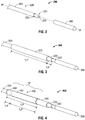
- FIGS. 2 through 8 show a sequentially-illustrated,assembly of components forming an energy applicator,shown generally as 800 in FIG. 8 , in accordance with the present disclosure.
- a coaxial feedline 226 is shown with the outer conductor 224 trimmed back, such that a portion 221 of the dielectric material 222 and the inner conductor 220 extends beyond the outer conductor 224.
- an energy applicator segment (shown generally as 200 in FIG.2 ) includes an electrically-conductive element260 that extends along the longitudinal axis "A" of the energy applicator segment 200.
- Electrically-conductive element 260 may be positioned in a distal portion of the energy applicator 1600.
- the electrically-conductive member 260 is a solid metal cylinder disposed at the distal end of the portion 221 electrically coupled to the inner conductor 220 (e.g., by solder).
- Electrically-conductive element 260 may be formed of any suitable electrically-conductive material (e.g.,metal such as stainless steel,aluminum, titanium,copper,etc.) of any suitable length.
- the shape and size of the electrically-conductive element 260 may be varied from the configuration depicted in FIG. 2 .
- FIG. 3 shows an energy applicator segment 300 according to the present disclosure that is similarto the energy applicator segment 200 of FIG. 2 , except for a dielectric layer 322 (also referred to herein as a balun insulator) disposed coaxially about a distal portion of the outer conductor 224 of the feedline 226.
- Dielectric layer 322 may have a suitable length "L1" in a range of about 0.1 inches (2.54mm) to about 3.0 inches (76.2mm).
- Dielectric layer 322 may be spaced apart from and disposed proximal to the distal end of the outer conductor 224.
- the dielectric layer 322 is spaced apart, by a length "L2", e.g., about 0.1 inches (2.54mm),from the distal end of the outer conductor 224.
- Balun insulator 322 may extend distally beyond the distal end of the conductive balun sleeve (e.g.,430 shown in FIG. 4 ) to direct current into a balancing/unbalancing (balun) structure (e.g., "B shown in FIG. 4 ).
- Dielectric layer 322 may be formed of any suitable insulative shown in FIG. 4 ).
- Dielectric layer 322 may be formed of any suitable insulative material, including, but not limited to, ceramics,water, mica, polyethylene, polyethylene terephthalate,polyimide, polytetrafluoroethylene (PTFE) (e.g.,Teflon®, manufactured by E.I. du Pont de Nemours and Company of Wilmington, Delaware, United States), glass,metal oxides or other suitable insulator, and may be formed in any suitable manner. Dielectric layer 322 may be grown,deposited or formed by any other suitable technique., The balun insulator 322 is formed from a material with a dielectric constant in the range of about 1.7 to about 10. The shape, size and relative position of the balun insulator 322 may be varied from the configuration depicted in FIG. 3 .
- FIG. 4 shows an energy applicator segment 400 according to the present disclosure that is similar to the energy applicator segment 300 of FIG. 3 except for an electrically-conductive layer 430 (also referred to herein as a conductive balun sleeve) disposed coaxially about a proximal portion of the energy applicator segment 400.
- Electrically-conductive layer 430 may have any suitable length "L3",e.g.,about0.1 inches (2.54mm) to about 3.0 inches(76.2mm).
- Electrically-conductive layer 430 may be formed as a single structure and electrically coupled to the outer conductor 224, e.g., by solder or other suitable electrical connection.
- the electrically-conductive layer 430 includes a first portion 431, having a length "L5", disposed coaxially about a proximal portion of the dielectric layer 322, and a second portion 432, having a length "L4", disposed proximally to the first portion 431 electrically coupled to the outer conductor 224.
- First and second portions 431, 432 may be formed of any suitable electrically-conductive material, e.g., metal such as stainless steel, titanium, copper, etc., and may be formed in any suitable manner.
- First and second portions 431, 432 may be formed separately from each other.
- First and second portions 431,432 may form a single, unitary structure.
- the shape and size of the electrically-conductive balun sleeve 430 may be varied from the configuration depicted in FIG. 4 .
- FIG. 5 shows an energy applicator segment 500 according to the present disclosure that is similar to the energy applicator segment 400 of FIG. 4 , except for an electrically-conductive cylinder 540 disposed coaxially about a distal portion of the electrically-conductive layer 430.
- Electrically-conductive cylinder 540 may have a suitable length "L6" in a range of about 0.05 inches (1.27mm) to about 0.2 inches (5.08mm).
- the distal edge of electrically-conductive cylinder 540 is disposed overlying the distal edge of the electrically-conductive layer 430.
- the shape and size of the electrically-conductive cylinder 540 may be varied from the configuration depicted in FIG. 5 .
- FIG.6 shows an energy applicator segment 600 according to the present disclosure that includes an electrically-conductive layer 630 and an electrically-conductive cylinder 640.
- Electrically-conductive layer 630 surrounds a proximal portion of the dielectric layer 322 and is electrically coupled to the outer conductor 224, e.g., by solder or other suitable electrical connection.
- Electrically-conductive layer 630 is similar to the electrically-conductive layer 430 of FIG. 4 , except that the electrically-conductive layer 630 has a length that is less than the length "L3" of the electrically-conductive layer 430. As shown in FIG. 6 , the electrically-conductive layer 630 may have a length "L7", which is shorter than the length "L3" by a length "L9".
- Electrically-conductive cylinder 640 shown in FIGS. 6 and 7 is similar to the electrically-conductive cylinder 540 of FIG. 5 ,except that the electrically-conductive cylinder 640 extends distally beyond the distal edge of the electrically-conductive layer 630.
- the electrically-conductive cylinder 640 having a length "L6”
- the electrically-conductive cylinder 640 includes a first portion 641, having a length "L8”, disposed coaxially about the distal end of the electrically-conductive layer 630, and a second portion 642, having a length "L9", disposed proximally to the first portion 641, surrounding a portion of the dielectric layer 322 distally extending beyond the electrically-conductive layer 630.
- the electrically-conductive cylinder 640 is positioned relative to the distal edge of the electrically-conductive layer 630 such that the combined length of the electrically-conductive layer 630 and the electrically- conductive cylinder 640 is a length "L3", which may be, for example, a quarter wavelength or a half wavelength.
- L3 may be, for example, a quarter wavelength or a half wavelength.
- the shape and size of the electrically-conductive cylinder 640 may be varied from the configuration depicted In FIGS. 6 and 7 .
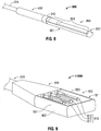
- FIG. 8 shows an energy applicator segment 800 according to the present disclosure that is similar to the energy applicator segment 500 of FIG. 5 , except for a generally longitudinally-disposed dielectric structure 850.
- the dielectric structure 850 includes a dielectric cap configured to cover the distal end of the electrically-conductive member 260.
- the dielectric structure 850 may be disposed distally to the electrically-conductive cylinder 540.
- Dielectric structure 850 may be formed using over-molding techniques or other forming techniques.
- the dielectric structure 850 is formed from a material with a dielectric constant in the range of about 1.7 to about 10. The shape and size of the dielectric structure 850 may be varied from the configuration depicted in FIG, 8 .
- the dielectric structure 850 includes a first dielectric segment 851, a second dielectric segment 852, and a third dielectric segment 853.
- the first dielectric segment 851 extends distally from the distal end of the electrically-conductive cylinder 540 and may have a substantially half-cylindrical shape.
- First dielectric segment 851 may be made to encompass any radial angle.
- the first dielectric segment 851 extends from the distal end of the electrically-conductive cylinder 540 to distal end of the electrically-conductive member 260.
- Second dielectric segment 852 is configured to cover the distal end of the electrically-conductive member 260, and may include a first portion (e.g., 852A shown in FIG.
- first and second dielectric segments 851,852 are integrally formed in a molding process.
- First dielectric segment 851, the second dielectric segment 852 and the third dielectric segment 853 may be formed by any suitable process.
- the energy applicator segment 800 may be provided with an outer jacket (not shown) disposed about the electrically-conductive layer 430,the electrically-conductive cylinder 540 and/or the dielectric structure 850.
- the outer jacket may be formed of any suitable material, such as, for example, polymeric or ceramic materials.
- the outer jacket may be applied by any suitable method, such as, for example, heat shrinking, over-molding, coating, spraying dipping, powder coating, baking and/or film deposition.
- the outer jacket may be a water-cooled catheter formed of a material having low electrical conductivity.
- FIG. 9 shows a portion or unit 1100A of an electromagnetic energy delivery device, such the electromagnetic energy delivery device 1200 of FIG. 11 , with an array of three energy applicators, such as the energy applicator 800 of FIG. 8 , in accordance with the present disclosure.
- the portion 1100A includes an applicator array assembly 950, a power divider unit 940 electrically coupleable to a generator assembly (e.g., 28 shown in FIG. 16 ) for dividing power for a plurality of channels (e.g., 450A,4508 and 450C shown in FIG. 21 ) connected to the applicator array assembly 950, and a handle member 930.
- Power divider unit 940 is similar to the power divider unit 140 of FIG. 18 and further description thereof is omitted in the interests of brevity.
- the applicator array assembly 950 includes a shell assembly 953 and an applicator array 810 including three energy applicators 811,812 and 813.
- the shell assembly 953 has a substantially rectangular shape,and may extend distally beyond the length of the radiating portion of the applicator array 810. The shape and size of the shell assembly 953 may be varied from the configuration depleted in FIG. 9 .
- the shell assembly 1240 has a substantially oblong shape.
- the portion 1100A of the electromagnetic energy delivery device illustrated in FIG. 9 includes three energy applicators 811,812 and 813, it is to be understood that any "N" number of energy applicators may be utilized.
- Shell assembly 953 may include an outer portion 951 and an inner portion 952.
- the outer portion 951 of the shell assembly 953 is formed of an electrically-conductive material e.g., stainless steel, and electrically coupled to the distal end of the conductive balun sleeve (e.g., 430 shown in FIG. 4 ) of one or more of the energy applicators 811, 812 and 813.
- Inner portion 952 of the shell assembly 953 may be formed of any suitable dielectric material. A distal portion of the inner portion 952 may extend distal to the distal ends of the energy applicators 811,812 and 813.
- Outer portion 951 may include any electrically-conductive material, such as, for example, copper, stainless steel, titanium, titanium alloys such as nickel-titanium and titanium-aluminum-vanadium alloys, aluminum, aluminum alloys, tungsten carbide alloys or combinations thereof. Portions of the outer portion 951 may be loaded with low- to mid-range permittivity dielectric materials to aid in radiation directivity and impedance matching. Several shells, or other shapes, of different dielectric materials may nest together to form the outer portion 951.
- Inner portion 952 may include a dielectric material.
- the inner portion 952 includes dielectric material layers.
- the inner portion 952 may include one or more thin layers, one or more thick layers or a mixture of thick and thin layers.
- Inner portion 952 may be composed of any suitable dielectric material which may be the same as, or different from, the dielectric material, if any, used in the outer portion 951.
- the dielectric materials used to form the inner portion 952 may vary in dielectric constant with shells or more complex dielectric layering to achieve the optimum antenna directivity and energy to tissue delivery.
- a portion of the cap of dielectric material 852 and a portion of the first dielectric segment 851 of one or more of the energy applicators 811,812 and 813 are disposed in a recess in the form of a groove (not shown) defined in the planar top surface "S" of the inner portion 952.
- the inner portion 952, or portions thereof, may be adapted to circulate coolant fluid therethrough.
- FIG. 10 shows a portion 11008 of an electromagnetic energy delivery device according to the present disclosure that is similarto the portion 1100A of FIG. 9 , except for a chamber 1060 (also referred to herein as a cooling chamber).
- Chamber 1060 generally includes a fluid inlet port (not shown) and a fluid outlet port (not shown).
- Coolant chamber 1060 is adapted to circulate coolant fluid (e.g., "F" shown in FIG. 11 ) therethrough, and may include baffles, multiple lumens, flow restricting devices, or other structures that may redirect, concentrate,or disperse flow depending on their shape.
- coolant fluid e.g., "F" shown in FIG. 11
- FIG. 11 shows an electromagnetic energy delivery device 1200 in accordance with the present disclosure that includes the portion 11008 of FIG. 10 shown with a material 1180 disposed about the cooling chamber 1060 thereof.
- Material 1180 may include any suitable material. Suitable materials for use as the material 1180 may include high dielectric-constant materials, such as, for example, inorganic nonmetallic materials (e.g.,ceramics), metallic oxides (e.g., alumina, titanium dioxide,zirconium dioxide, or zinc oxide) and combinations thereof.
- Material 1180 may include a nonconductive radio frequency transparent material, e.g., a glass fiber epoxy composite polyimide, high temperature conformable rubber or plastic. Material 1180 may be formed using over-molding techniques or other forming techniques.
- FIG. 12 shows an energy applicator segment 900 according to an embodiment of the present disclosure that is similar to the energy applicator segment 800 of FIG. 8 , except for a longitudinally-extending inflow tube 961, a longitudinally-extending outflow tube 962, and an electrically-conductive cylinder 940 having a notch "N" defined therein that is configured to receive the inflow and outflow tubes 961,962.
- the inflow and outflow tubes 961, 962 are configured to supply and/or dispense coolant fluid (e.g., saline,water or other suitable coolant fluid) into and out of a distal portion of a cooling chamber (e.g., 1560 shown in FIG. 15 ).
- coolant fluid e.g., saline,water or other suitable coolant fluid
- a pump may be connected in fluid communication between the cooling chamber and a coolant source (e.g., 18 shown in FIG. 1A ).
- Inflow and outflow tubes 961,962 may include thin-walled polyimide tubes.
- a pump supplies coolant fluid from a coolant source to one or more inflow tubes 961which,in turn,deliver coolant fluid to the cooling chamber (e.g., 1560 shown in FIG. 15 ).
- a pump may be fluidly coupled to one or more outflow tubes 962 to draw coolant fluid out of the cooling chamber.
- the inflow and outflow tubes 961,962 may extend longitudinally across the full length of the electrically-conductive layer 430 and at least partially across the dielectric structure 850. As shown in FIG. 13 , a portion or segment "S" of the inflow and outflow tubes 961,962 is disposed within a notch "N" defined within the electrically-conductive cylinder 940.
- the notch "N" is configured as a recess,e.g., In the form of a groove or hole.
- the notch "N" is configured as a first recess (not shown) and a second recess (not shown), wherein the first recess is configured to receive one or more inflow tubes 961 and the second recess is configured to receive one or more outflow tubes 962.
- Inflow tube 961 and the outflow tube 962 may be formed to have the same diameters or different diameters.
- Inflow and outflow tubes 961, 962 may have any suitable length.
- the segment "S" of the inflow and outflow tubes 961, 962 is disposed between the electrically-conductive layer 430 and the outer circumferential surface of the electrically-conductive cylinder 940, which helps minimize the outer diameter of the energy applicator.
- Inflow and outflow tubes 961, 962 may be held in place,e.g., along the electrically-conductive layer 430 and/or within the notch "N",by using UV adhesive or other similar suitable adhesives,as well as heat shrink tubing or by other suitable methods.
- the shape and size of the inflow and outflow tubes 961,962, the electrically-conductive cylinder 940 and the notch "N" may be varied from the configurations depicted in FIGS. 12 and 13 .
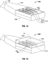
- FIG. 14 shows a portion 1400 of an electromagnetic energy delivery device that is similar to the portion 1100A of the electromagnetic energy delivery device of FIG. 9 .
- the portion 1400 Includes an applicator array assembly 1450, a power divider unit 940 electrically coupleable to a generator assembly (e.g., 28 shown in FIG.16 ) for dividing power for a plurality of channels connected to the applicator array assembly 1450,and a handle member 930.
- Power divider unit 940 is similar to the power divider unit 140 of FIG.1B and further description thereof is omitted in the interests of brevity.
- Applicator array assembly 1450 is similar to the applicator array assembly 950 shown in FIG.
- the inflow and outflow tubes 961, 962 are configured to supply and/or dispense coolant fluid "F" (e.g., saline water or other suitable coolant fluid) into and out of a cooling chamber (e.g.,1560 shown in FIG. 15 ).
- coolant fluid "F" e.g., saline water or other suitable coolant fluid
- FIG. 15 shows an electromagnetic energy delivery device 1500 in accordance with the present disclosure that includes the portion 1400 of FIG. 14 shown with a cooling chamber 1560 and a material 1580 disposed thereabout.
- Cooling chamber 1560 at least partially surrounds the energy applicator array 1210.
- the shape and size of the inflow and outflow tubes 961,962 and the chamber 1560 may be varied from the configuration depicted in FIG. 15 . Portions of the inflow and outflow tubes 961,962 are disposed within the chamber 1560.
- the chamber 1560 may include a material having a high dielectric constant, such as alumina, titanium dioxide or zirconium dioxide, for improved antenna directivity and energy to tissue delivery efficiency. Cooling chamber 1560 and the material 1580 disposed thereabout are similar to the chamber 1060 and the material 1080 shown in FIGS. 10 and 11 , respectively, and further description thereof is omitted in the interests of brevity.
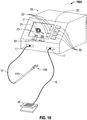
- FIG. 16 schematically illustrates an electrosurgical system 1000 in accordance with the present disclosure.
- Electrosurgical system 1000 includes an actuator 20 operably coupled by a cable 19 via connector 17 to the generator assembly 28 of the electrosurgical system 10 of FIG. 1A .
- Actuator 20 may be a footswitch, a handswitch, a bite-activated switch, or any other suitable actuator.
- Cable 19 may include one or more electrical conductors for conveying an actuation signal from the actuator 20 to the generator assembly 28.
- the actuator 20 is operably coupled to the generator assembly 28 by a wireless link, such as without limitation, a radiofrequency or infrared link.
- the clinician may interact with the user interface 205 to preview operational characteristics of the electromagnetic energy delivery device 100.
- Generator assembly 28 includes a generator module (e.g.,286 shown in FIG. 17 ) in operable communication with a processor (e.g., 282 shown in FIG. 17 ), a user interface 25, and an actuator 20.
- Electromagnetic energy delivery device 100 is operably coupled to an energy output of the generator module, which may be configured as a source of RF and/or microwave energy.
- Actuator 20 is operably coupled to the processor via user interface 21.
- Actuator 20 may be operably coupled to the processor and/or to the generator module by a cable connection, or a wireless connection.
- User interface 25 may include a display 21, such as without limitation a flat panel graphic LCD (liquid crystal display), adapted to visually display at least one user interface element 23,24.
- Display 21 includes touchscreen capability (not shown), e.g., the ability to receive input from an object in physical contact with the display,such as without limitation, a stylus or a user's fingertip.
- a user interface element 23, 24 may have a corresponding active region, such that, by touching the screen within the active region associated with the user interface element, an input associated with the user interface element 23, 24 is received by the user interface 25.
- User interface 25 may additionally, or alternatively, include one or more controls 22 that may include without limitation a switch (e.g., pushbutton switch, toggle switch, slide switch) and/or a continuous actuator (e.g., rotary or linear potentiometer, rotary or linear encoder.)
- a control 22 has a dedicated function, e.g., display contrast, power on/off, and the like. Control 22 may also have a function that may vary in accordance with an operational mode of the electrosurgical system 10.
- a user interface element 23 may be positioned substantially adjacently to control 22 to indicate the function thereof. Control 22 may also include an indicator, such as an illuminated indicator (e.g., a single- or variably-colored LED indicator).
- FIG. 17 is a block diagram showing the electrosurgical system 1000 of FIG. 16 .
- the generator module 86 is configured to provide energy of about 915 MHz.
- Generator module 86 may additionally, or alternatively, be configured to provide energy of about 2450 MHz (2.45 GHz).
- the present disclosure contemplates that the generator module 286 is configured to generate a frequency other than about 915 MHz or about 2450 MHz, and the generator module 86 is configured to generate variable frequency energy.
- Generator assembly 28 includes a processor 82 that is operably coupled to user interface 21.
- Processor 82 may include any type of computing device, computational circuit, or any type of processor or processing circuit capable of executing a series of instructions that are stored in a memory, e.g., storage device 88 or external device 91.
- a storage device 88 is operably coupled to the processor 82, and may include random-access memory (RAM), read-only memory (ROM), and/or non-volatile memory (NV-RAM, Flash,and disc-based storage.)
- Storage device 88 may include a set of program instructions executable on the processor 82 for executing a method for displaying and controlling ablation patterns in accordance with the present disclosure.
- Generator assembly 200 may include a data interface 90 that is configured to provide a communications link to an external device 91.
- the data interface 90 may be any of a USB interface, a memory card slot (e.g., SD slot ⁇ , and/or a network interface (e.g., 100BaseT Ethernet interface or an 802.11 "Wi-Fi" interface.)
- External device 91 may be any of a USB device (e.g., a memory stick), a memory card (e.g., an SD card), and/or a network-connected device (e.g., computer or server).
- Generator assembly 28 may also include a database 84 that is configured to store and retrieve energy applicator data,e.g., parameters associated with one or energy applicators (e.g., "A 1 ", “A 2 ", “A N “ shown in FIG. 1B ⁇ and/or one or more applicator array assemblies (e.g., 150 shown in FIG. 18 ).
- Parameters stored in the database 84 in connection with a applicator array assembly may include, but are not limited to, applicator array assembly identifier, applicator array assembly dimensions, a frequency, an ablation length, an ablation diameter, a temporal coefficient, a shape metric, and/or a frequency metric.
- An ablation pattern topology may be included in the database 84, e.g., a wireframe model of an applicator array assembly (e.g., 150 shown in FIG. 1B ) and/or an ablation pattern associated therewith.
- Database 84 may also be maintained at least in part by data provided by the external device 91 via the data interface 90.
- energy applicator data may be uploaded from an external device 91 to the database 84 via the data interface 90.
- Energy applicator data may additionally, or alternatively, be manipulated, e.g., added, modified, or deleted, in accordance with data and/or instructions stored on the external device 91.
- the set of energy applicator data represented in the database 84 is automatically synchronized with corresponding data contained in external device 91 in response to external device 91 being coupled (e.g., physical coupling and/or logical coupling) to data interface 90.
- Processor 82 is programmed to enable a user, via user interface 25 and/or display 21, to view at least one ablation pattern and/or other energy applicator data corresponding to an applicator array assembly. For example, a surgeon may determine that a substantially spherical ablation pattern is necessary. The surgeon may activate a "select ablation shape" mode of operation for generator assembly 28, preview an energy applicator array by reviewing graphically and textually presented data on display 21, optionally, or alternatively, manipulate a graphic image by, for example, rotating the image, and to select an array of energy applicators based upon displayed parameters. The selected energy applicator(s) may then be electrically coupled to the generator assembly 28 for use therewith.
- a surgeon may input via user interface 25 an applicator array parameter to cause generator assembly 28 to present one or more electromagnetic energy delivery devices corresponding thereto. For example, a surgeon may require a 3.0 cm x 3.0 cm ablation pattern, and provide an input corresponding thereto.
- the generator assembly 28 may preview a corresponding subset of available electromagnetic energy delivery devices 100 that match or correlate to the inputted parameter.
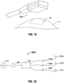
- FIG. 18 is a diagrammatic representation of a radiation pattern "R" of electromagnetic energy delivered Into tissue "T” by an electromagnetic energy delivery device, such as the electromagnetic energy delivery device 1200 of FIG. 11 , according to the present disclosure.
- FIG. 19 is a schematic diagram of an electrosurgical system 2000 for treating tissue according to the present disclosure.
- Electrosurgical system 2000 includes a microwave signal source 210 providing a microwave frequency output signal to a microwave amplifier unit 230, a phase-balanced microwave power splitter 240 coupled to the microwave amplifier unit 230, and a first, a second and a third microwave ablation antenna assembly 270A,2706 and 270C, each coupled to the phase-balanced microwave power splitter 240.
- the microwave signal source 210 is capable of generating a plurality of output signals of various frequencies that are input to the microwave amplifier unit 230.
- the microwave amplifier unit 230 may have any suitable input power and output power.
- a first transmission line 250A electrically connects the first antenna assembly 270A to the phase-balanced microwave power splitter 240, defining a first channel
- a second transmission line 250B electrically connects the second antenna assembly 270B to the phase-balanced microwave power splitter 240,defining a second channel
- a third transmission line 250C electrically connects the third antenna assembly 270C to the phase-balanced microwave power splitter 240, defining a third channel.
- the first,second and third transmission lines 250A, 250B and 250C may each include one or more electrically conductive elements,such as electrically conductive wires.
- the first, second and third transmission lines 250A, 250B and 250C each have substantially the same length,which preserves the phase relationship between the electrical signals in each channel of the electrosurgical system 2000.
- the phase-balanced microwave power splitter 240 may be implemented by any suitable power divider that provides equal power split at all output ports while substantially maintaining phase.
- the phase-balanced microwave power splitter 240 may be implemented using a 3-way power divider that provides equal power split at all output ports while maintaining a phase balance of ⁇ +/-45 degrees.
- the phase-balanced microwave power splitter 240 may be implemented by any suitable power divider that provides equal power split at all output ports while substantially maintaining phase and amplitude balance.
- the phase-balanced microwave power splitter 240 implements using a 3-way power divider that provides equal power split at all output ports while maintaining a phase balance of ⁇ +/-10 degrees and amplitude balance of ⁇ 1.5 dB.
- Each antenna assembly 270A,270B and 270C typically Includes a plurality of electrodes disposed on a rigid or bendable needle or needle-like structure.
- the antenna assemblies 270A, 270B and 270C are positioned substantially parallel to each other, for example, spaced about 5 millimeters (mm) apart,and inserted directly into tissue or placed into the body during surgery by a clinician,or positioned in the body by other suitable methods.
- mm millimeters
- microwave ablation antenna assemblies 270A, 270B and 270C include three microwave ablation antenna assemblies 270A, 270B and 270C, it is to be understood that any "N" number of antenna assemblies may be utilized and that phase-balanced microwave power splitter 240 may be implemented by any suitable power divider that divides or splits a microwave input signal into "N" number of output signals of equal power while substantially maintaining phase and amplitude balance.
- the electrosurgical system 2000 delivers phase-controlled microwave power to each antenna assembly 270A, 270B and 270C of the three-channel system.
- the electrosurgical system 2000 delivers substantially in-phase microwave power to each antenna assembly 270A, 270B and 270C, which may result in a more efficient ablating tool than out-of-phase energy applicators.
- By controlling the phase of energy applicators with respect to each other a desired effect on tissue between the energy applicators is produced.
- energy applicators that are 180 degrees out of phase with respect to each other produce a desired effect on tissue.
- ablation procedures using in-phase energy applicators there may be a reduction in energy that might otherwise move between the antenna shafts toward the surface with out-of-phase energy applicators.
- the electrosurgical system 2000 delivers phase-controlled microwave power to each antenna assembly 270A, 270B and 270C while maintaining a phase balance of ⁇ +/- 45 degrees.
- the electrosurgical system 2000 is implemented with operating frequencies in the range of about 915 MHz to about 5 GHz,which may be useful in performing ablation procedures and/or other procedures. It is to be understood that the electrosurgical system 2000 may be implemented with any appropriate range of operating frequencies.
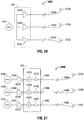
- FIG. 20 is a schematic diagram of an electrosurgical system 3000 for treating tissue according to the present disclosure.
- Electrosurgical system 3000 includes a microwave signal source 310 providing a microwave frequency output signal to a controller 330,and a first, a second and a third microwave ablation antenna assembly 270A, 270B and 270C, each coupled to the controller 330.
- the microwave signal source 310 is capable of generating a plurality of output signals of various frequencies that are input to the controller 330.
- the controller 330 includes a first, a second and a third microwave amplifier 320A, 320B and 320C that are phase-balanced with respect to one another.
- the first, second and third phase-balanced microwave amplifiers 320A, 320B and 320C each deliver equal power while maintaining a phase balance of ⁇ +/-10 degrees and amplitude balance of ⁇ 1.5 dB.
- the first, second and third phase- balanced microwave amplifiers 320A, 320B and 320C each deliver phase-controlled microwave power to the respective antenna assemblies 270A, 270B and 270C while maintaining a phase balance of ⁇ +/-45 degrees.
- the first, second and third phase-balanced microwave amplifiers 320A, 320B and 320C may have any suitable input power and output power.
- a first transmission line 350A electrically connects the first antenna assembly 270A to the first phase-balanced microwave amplifier 320A, defining a first channel
- a second transmission line 350B electrically connects the second antenna assembly 270B to the second phase-balanced microwave amplifier 320B, defining a second channel
- a third transmission line 350C electrically connects the third antenna assembly 270C to the third phase-balanced microwave amplifier 320C, defining a third channel.
- the first, second and third transmission lines 350A, 350B and 350C each include one or more electrically conductive elements, such as electrically conductive wires.
- the first, second and third transmission lines 350A, 350B and 350C each have substantially the same length, which preserves the phase relationship between electrical signals in each channel of the electrosurgical system 300.
- the electrosurgical system 3000 illustrated in FIG. 20 includes three microwave ablation antenna assemblies 270A, 270B and 270C and three phase-balanced microwave amplifiers 320A, 320B and 320C, it is to be understood that any "N" number of antenna assemblies and any “N” number of phase-balanced microwave amplifiers may be utilized.
- FIG. 21 is a schematic diagram of an electrosurgical system 4000 for treating tissue according to the present disclosure.
- the disclosed electrosurgical system 4000 is a three-channel system that includes a first, a second and a third microwave signal source 410A, 410B and 410C, a first, a second and a third microwave amplifier 420A, 420B and 420C, a controller 440 that includes three inputs 442A,442B and 442C and three outputs 448A, 448B and 448C,and a first, a second and a third microwave ablation antenna assembly 270A,270B and 270C.
- the first, second and third microwave signal sources 410A, 410B and 410C provide microwave frequency output signals to the first, second and third amplifiers 420A, 420B and 420C, respectively.
- the first microwave amplifier 420A provides an output signal through an output terminal that is electrically coupled to the first input 442A of the controller 440;
- the second microwave amplifier 420B provides an output signal through an output terminal that is electrically coupled to the second input 442B of the controller 440;
- the third microwave amplifier 420C provides an output signal through an output terminal that is electrically coupled to the third input 442C of the controller 440.
- the first, second and third amplifiers 420A, 420B and 420C each have any suitable input power and output power.
- the first, second and third amplifiers 420A,420B and 420C may be phase-balanced with respect to one another and, in such case, are arranged between the controller 440 and the first, second and third microwave ablation antenna assemblies 270A, 270B and 270C.
- first, second and third amplifiers 420A, 420B and 420C are illustrated as standalone modules in FIG. 21 , it is to be understood that one or more of the amplifiers may be integrated fully or partially into the controller 440.
- the electrosurgical system 4000 may be implemented without the first, second and third amplifiers 420A,420B and 420C, or with any combination thereof.
- the controller 440 includes a first, a second and a third phase shifter 443A, 443B and 443C, and a first,a second and a third phase monitor unit 447A, 447B and 447C.
- the first phase shifter 443A is electrically coupled between the first input 442A and the first phase monitor unit 447A;
- the second phase shifter 443B is electrically coupled between the second input 442B and the second phase monitor unit 447B;
- the third phase shifter 443C is electrically coupled between the third input 442C and the third phase monitor unit 447C.
- the first phase monitor unit 447A is electrically coupled between the first phase shifter 443A and the output 448A; the second phase monitor unit 447B is electrically coupled between the second phase shifter 443B and the output 448B; and the third phase monitor unit 447C is electrically coupled between the third phase shifter 443C and the output 448C.
- the controller 440 may include a number of processing units (not shown) coupled to the first,second and third phase monitor units 447A,447B and 447C for controlling output of one or more of the phase shifters 443A, 443B and 443C to provide a desired phase relationship of electrical signals in each channel of the electrosurgical system 4000.
- the processing unit(s) may include multiple processors and/or multicore CPUs and may include any type of processor capable of executing software, such as a microprocessor, digital signal processor, microcontroller, or the like.
- the controller 440 may additionally, or alternatively, be operably coupled to an external processor (e.g., 82 shown in FIG. 16 ).
- the controller 440 may include one or more phase detectors (not shown) to compare the respective phases of electrical signals inputted through the inputs 442A, 442B and/or 442C. By comparing a reference signal, such as a clock signal,to a feedback signal using a phase detector, phase adjustments may be made based on the comparison of the electrical signals inputted,to set the phase relationship between electrical signals in each channel of the electrosurgical system 4000.
- phase detectors not shown
- the controller 440 delivers phase-controlled microwave power through the outputs 448A, 448B and 448C to the antenna assemblies 270A, 270B and 270C, respectively irrespective of the individual phases of each of electrical signals inputted through the inputs 442A, 442B and/or 442C. As illustrated in FIG.
- a first transmission line 450A electrically connects the first antenna assembly 270A to the output 448A of the controller 440,defining a first channel
- a second transmission line 450B electrically connects the second antenna assembly 270B to the output 448B of the controller 440,defining a second channel
- a third transmission line 450C electrically connects the third antenna assembly 270C to the output 448C of the controller 440, defining a third channel.
- the first, second and third transmission lines 450A, 450B and 450C each include one or more electrically conductive elements, such as electrically conductive wires.
- the first, second and third transmission lines 450A, 450B and 450C each have substantially the same length, which preserves the phase relationship between electronical signals in each channel of the electrosurgical system 400.
- FIG. 22 is a flowchart illustrating a method of manufacturing an electromagnetic energy delivery device according to the present disclosure.
- a plurality of coaxial cables is provided.
- Each coaxial cable e.g., 226 shown in FIG. 2
- includes an inner conductor e.g., 220 shown in FIG. 2
- an outer conductor e.g., 224 shown in FIG. 2
- a dielectric material e.g., 222 shown in FIG. 2
- a portion of the inner conductor and the dielectric material may extend beyond the outer conductor at the distal end of the coaxial cable.
- a plurality of first applicator segments is formed by joining an elongated electrically-conductive member (e.g.,260 shown in FIG. 2 ) to the distal end of the inner conductor (e.g., 220 shown in FIG. 2 ) of each of the plurality of coaxial cables.
- the electrically-conductive member is a solid metal cylinder electrically coupled to the inner conductor, e.g., by solder or other suitable electrical connection.
- a plurality of second applicator segments is formed by joining a balun structure (e.g.,"B" shown in FIG. 4 ) to a distal portion of the outer conductor (e.g., 224 shown in FIG. 3 ) of each of the plurality of first applicator segments.
- the balun structure may be a quarter wavelength sleeve balun.
- the balun structure includes a balun insulator (e.g.,322 shown in FIG. 3 ) coaxially disposed around a distal portion of the outer conductor, and an electrically- conductive balun sleeve (e.g.,430 shown in FIG.
- balun insulator may extend distally beyond the distal end of the electrically-conductive balun sleeve to direct currents into the balun.
- a plurality of third applicator segments is formed by positioning an electrically-conductive cylinder (e.g., 540 shown in FIG.5 ) overlying a distal portion of the balun structure of each of the plurality of second applicator segments.
- a portion (e.g., 642 shown in FIG. 7 ) of the electrically- conductive cylinder (e.g., 640 shown in FIGS. 6 and 7 ) extends distally beyond the distal edge of an electrically-conductive balun sleeve (e.g., 630 shown in FIG. 7 ) of the balun.
- the electrically-conductive cylinder is positioned relative to the distal edge of the electrically-conductive balun sleeve such that the combined length of the conductive balun sleeve and the conductive cylinder is a quarter wavelength or a half wavelength.
- a plurality of energy applicators is formed by forming a dielectric structure (e.g., 850 shown in FIG. 8 ) having a proximal end disposed substantially adjacent to a distal end of the electrically-conductive cylinder of each of the plurality of third applicator segments, wherein each dielectric structure longitudinally extends from the distal end of the electrically-conductive cylinder to a distal end of the electrically-conductive member.
- the dielectric structure includes a cap of dielectric material (e.g., 852 shown in FIG. 8 ) configured to cover the distal end of the electrically-conductive member.
- the dielectric structure may be formed using over-molding techniques or other forming techniques.
- an applicator array assembly (e.g.,950 shown in FIG. 9 ) is formed including the plurality of energy applicators (e.g., 811, 812, 813 shown in FIG. 9 ) and a cooling chamber (e.g., 1060 shown in FIG. 10 ) disposed at least partially surrounding the plurality of energy applicators configured for circulating coolant fluid (e.g., "F" shown in FIG. 11 ) thereabout.
- a cooling chamber e.g., 1060 shown in FIG. 10
- a power divider unit (e.g.,940 shown in FIG. 11 ) for dividing power for a plurality of channels (e.g., 250A,250B, 250C shown in FIG. 19 ) connected to the applicator array assembly is provided, wherein each channel may be connectable to any one or more of the energy applicators of the applicator array assembly.
- the above-described electrosurgical systems for treating tissue and methods of directing electromagnetic radiation to a target volume of tissue may be used to provide directional microwave ablation, wherein the heating zone may be focused to one side of the electrosurgical device, thereby allowing clinicians to target small and/or hard tumors without having to penetrate the tumor directly or kill more healthy tissue than necessary.
- the presently disclosed electrosurgical devices may allow clinicians to avoid ablating critical structures, such as large vessels, healthy organs or vital membrane barriers, by placing the electrosurgical device between the tumor and critical structure and directing the electromagnetic radiation toward the tumor and away from the sensitive structure.
Landscapes
- Health & Medical Sciences (AREA)
- Surgery (AREA)
- Life Sciences & Earth Sciences (AREA)
- Engineering & Computer Science (AREA)
- Biomedical Technology (AREA)
- Molecular Biology (AREA)
- Nuclear Medicine, Radiotherapy & Molecular Imaging (AREA)
- Electromagnetism (AREA)
- Physics & Mathematics (AREA)
- Heart & Thoracic Surgery (AREA)
- Medical Informatics (AREA)
- Otolaryngology (AREA)
- Animal Behavior & Ethology (AREA)
- General Health & Medical Sciences (AREA)
- Public Health (AREA)
- Veterinary Medicine (AREA)
- Manufacturing & Machinery (AREA)
- Surgical Instruments (AREA)
Claims (13)
- Elektrochirurgisches System zum Richten von Energie auf Gewebe (T), umfassend:eine Generatorbaugruppe (28, 310, 410A-C), die betriebsbereit ist, um Leistung mit einer ausgewählten Phase, Amplitude und Frequenz zuzuführen; undeine Applikator-Array-Baugruppe (270A-C, 950, 1100A, 1450), beinhaltend:eine Gehäusebaugruppe (953);eine Vielzahl von Energieapplikatoren (811, 812, 813), die innerhalb der Gehäusebaugruppe angeordnet sind; undeine Leistungsteilereinheit (240, 440, 940), die mit der Generatorbaugruppe elektrisch gekoppelt ist, wobei die Leistungsteilereinheit betriebsbereit ist, um Leistung in die Applikator-Array-Baugruppe aufzuteilen;wobei jeder der Vielzahl von Energieapplikatoren Folgendes beinhaltet:eine Länge eines koaxialen Kabels (226) mit einem Innenleiter (220), einem koaxial um den Innenleiter angeordneten Außenleiter (224) und einem dazwischen angeordneten dielektrischen Material (222);ein längliches elektrisch leitendes Element (260), das an einem distalen Ende des Innenleiters in Längsrichtung angeordnet ist;eine Balunstruktur (B, 322, 430, 431, 432), die auf dem Außenleiter (224) angeordnet ist;einen elektrisch leitenden Zylinder (540), der koaxial um einen distalen Abschnitt der Balunstruktur angeordnet ist; undeine dielektrische Struktur (850, 851, 852), die im Wesentlichen angrenzend an ein distales Ende des elektrisch leitenden Zylinders (540) angeordnet ist, wobei sich die dielektrische Struktur vom distalen Ende des elektrisch leitenden Zylinders zu einem distalen Endes des elektrisch leitenden Elements erstreckt.
- Elektrochirurgisches System nach Anspruch 1, wobei die Leistungsteilereinheit (440) eine Vielzahl von Phasenverschiebern (443A-C) beinhaltet.
- Elektrochirurgisches System nach Anspruch 2, wobei die Leistungsteilereinheit weiter eine Vielzahl von Phasenüberwachungseinheiten (447A-C), die zwischen der Vielzahl von Phasenverschiebern und der Vielzahl von Energieapplikatoren elektrisch gekoppelt sind, beinhaltet.
- Elektrochirurgisches System nach Anspruch 1, wobei die Leistungsteilereinheit einen phasensymmetrischen Mikrowellenleistungssplitter (240, 330) beinhaltet.
- Elektrochirurgisches System nach Anspruch 4, wobei die Leistungsteilereinheit (240, 330) der Vielzahl von Energieapplikatoren eine im Wesentlichen gleiche Leistungssplittung bereitstellt, während eine Phasensymmetrie von <+/-45 Grad aufrechterhalten wird.
- Elektrochirurgisches System nach Anspruch 1, wobei die Gehäusebaugruppe (953) einen aus einem elektrisch leitfähigen Material gebildeten Außenabschnitt (951) beinhaltet.
- Elektrochirurgisches System nach Anspruch 1, wobei die Gehäusebaugruppe eine im Wesentlichen rechtwinklige Form aufweist.
- Elektrochirurgisches System nach Anspruch 1, wobei die Generatorbaugruppe Folgendes beinhaltet:ein Generatormodul (86), das konfiguriert ist, um elektromagnetische Energie bereitzustellen;einen Prozessor (82), der betriebsbereit mit dem Generatormodul gekoppelt ist; undeine Benutzerschnittstelle (21), die betriebsbereit mit dem Prozessor gekoppelt ist,eine Benutzerschnittstelle, die konfiguriert ist, um ein Bild anzuzeigen, das einem Ablationsmuster (R) entspricht, das mit einer Applikator-Array-Baugruppe assoziiert ist.
- Elektrochirurgisches System nach Anspruch 8, wobei die Generatorbaugruppe weiter beinhaltet:
eine Datenbank (84) in betriebsbereiter Verbindung mit dem Prozessor und angepasst, um mit mindestens einer Applikator-Array-Baugruppe assoziierte Parameter zu speichern. - Elektrochirurgisches System nach Anspruch 1, wobei die Balunstruktur (B) eine Viertelwellenlängenhülse ist.
- Elektrochirurgisches System nach Anspruch 1, wobei die Gehäusebaugruppe einen aus einem elektrisch leitenden Material gebildeten Außenabschnitt beinhaltet, wobei der Außenabschnitt mit dem distalen Ende der leitenden Balunhülse mindestens einer der Vielzahl von Energieapplikatoren elektrisch gekoppelt ist.
- Elektrochirurgisches System nach Anspruch 1, wobei die Applikator-Array-Baugruppe weiter eine Kühlmittelkammer (1560), ein Einströmrohr (961), das konfiguriert ist, um der Kühlmittelkammer Kühlmittelfluid zuzuführen, und ein Ausströmrohr (962), das konfiguriert ist, um Kühlmittelfluid aus der Kammer abzugeben, umfasst.
- Elektrochirurgisches System nach Anspruch 1, wobei die dielektrische Struktur (850, 851, 852, 853) eine semizylindrische Form um das elektrisch leitende Element (260) aufweist.
Applications Claiming Priority (1)
| Application Number | Priority Date | Filing Date | Title |
|---|---|---|---|
| US12/620,289 US8394092B2 (en) | 2009-11-17 | 2009-11-17 | Electromagnetic energy delivery devices including an energy applicator array and electrosurgical systems including same |
Publications (2)
| Publication Number | Publication Date |
|---|---|
| EP2324788A1 EP2324788A1 (de) | 2011-05-25 |
| EP2324788B1 true EP2324788B1 (de) | 2020-01-01 |
Family
ID=43805770
Family Applications (1)
| Application Number | Title | Priority Date | Filing Date |
|---|---|---|---|
| EP10014705.7A Active EP2324788B1 (de) | 2009-11-17 | 2010-11-17 | Vorrichtungen zur Abgabe elektromagnetischer Energie, die eine Energieapplikatoranordnung enthalten, und elektrochirurgische Systeme, die diese Vorrichtungen enthalten |
Country Status (2)
| Country | Link |
|---|---|
| US (3) | US8394092B2 (de) |
| EP (1) | EP2324788B1 (de) |
Families Citing this family (78)
| Publication number | Priority date | Publication date | Assignee | Title |
|---|---|---|---|---|
| US6104959A (en) | 1997-07-31 | 2000-08-15 | Microwave Medical Corp. | Method and apparatus for treating subcutaneous histological features |
| US7553309B2 (en) | 2004-10-08 | 2009-06-30 | Covidien Ag | Electrosurgical system employing multiple electrodes and method thereof |
| US9375246B2 (en) * | 2007-01-19 | 2016-06-28 | Covidien Lp | System and method of using thermal and electrical conductivity of tissue |
| EP2142125B1 (de) | 2007-04-19 | 2014-03-05 | Miramar Labs, Inc. | Vorrichtungen und systeme zur nicht-invasiven verabreichung von mikrowellen-therapie |
| US8292880B2 (en) | 2007-11-27 | 2012-10-23 | Vivant Medical, Inc. | Targeted cooling of deployable microwave antenna |
| KR102052152B1 (ko) | 2007-12-12 | 2020-01-08 | 미라마 랩스 인코포레이티드 | 마이크로파 에너지를 방사하는 어플리케이터와 사용하기 위한 일회용 의료 장치 |
| EP2271276A4 (de) * | 2008-04-17 | 2013-01-23 | Miramar Labs Inc | Systeme, vorrichtung, verfahren und vorgehensweisen zur nichtinvasiven behandlung von gewebe mit mikrowellenenergie |
| US8403924B2 (en) | 2008-09-03 | 2013-03-26 | Vivant Medical, Inc. | Shielding for an isolation apparatus used in a microwave generator |
| US9700712B2 (en) * | 2009-01-26 | 2017-07-11 | Arizona Board Of Regents, A Body Corporate Of The State Of Arizona Acting For And On Behalf Of Arizona State University | Dipolar antenna system and related methods |
| US8632534B2 (en) | 2009-04-03 | 2014-01-21 | Angiodynamics, Inc. | Irreversible electroporation (IRE) for congestive obstructive pulmonary disease (COPD) |
| US8292881B2 (en) | 2009-05-27 | 2012-10-23 | Vivant Medical, Inc. | Narrow gauge high strength choked wet tip microwave ablation antenna |
| US8903488B2 (en) | 2009-05-28 | 2014-12-02 | Angiodynamics, Inc. | System and method for synchronizing energy delivery to the cardiac rhythm |
| US9895189B2 (en) | 2009-06-19 | 2018-02-20 | Angiodynamics, Inc. | Methods of sterilization and treating infection using irreversible electroporation |
| US8328800B2 (en) | 2009-08-05 | 2012-12-11 | Vivant Medical, Inc. | Directive window ablation antenna with dielectric loading |
| US8328799B2 (en) | 2009-08-05 | 2012-12-11 | Vivant Medical, Inc. | Electrosurgical devices having dielectric loaded coaxial aperture with distally positioned resonant structure |
| US8328801B2 (en) | 2009-08-17 | 2012-12-11 | Vivant Medical, Inc. | Surface ablation antenna with dielectric loading |
| US8069553B2 (en) | 2009-09-09 | 2011-12-06 | Vivant Medical, Inc. | Method for constructing a dipole antenna |
| US9113925B2 (en) * | 2009-09-09 | 2015-08-25 | Covidien Lp | System and method for performing an ablation procedure |
| US9095359B2 (en) | 2009-09-18 | 2015-08-04 | Covidien Lp | Tissue ablation system with energy distribution |
| US8568398B2 (en) | 2009-09-29 | 2013-10-29 | Covidien Lp | Flow rate monitor for fluid cooled microwave ablation probe |
| US8568401B2 (en) * | 2009-10-27 | 2013-10-29 | Covidien Lp | System for monitoring ablation size |
| US8382750B2 (en) | 2009-10-28 | 2013-02-26 | Vivant Medical, Inc. | System and method for monitoring ablation size |
| US8430871B2 (en) | 2009-10-28 | 2013-04-30 | Covidien Lp | System and method for monitoring ablation size |
| US8469953B2 (en) | 2009-11-16 | 2013-06-25 | Covidien Lp | Twin sealing chamber hub |
| US8394092B2 (en) | 2009-11-17 | 2013-03-12 | Vivant Medical, Inc. | Electromagnetic energy delivery devices including an energy applicator array and electrosurgical systems including same |
| US20110125148A1 (en) * | 2009-11-17 | 2011-05-26 | Turner Paul F | Multiple Frequency Energy Supply and Coagulation System |
| US8551083B2 (en) | 2009-11-17 | 2013-10-08 | Bsd Medical Corporation | Microwave coagulation applicator and system |
| US8764744B2 (en) | 2010-01-25 | 2014-07-01 | Covidien Lp | System for monitoring ablation size |
| US8491579B2 (en) | 2010-02-05 | 2013-07-23 | Covidien Lp | Electrosurgical devices with choke shorted to biological tissue |
| US8968288B2 (en) | 2010-02-19 | 2015-03-03 | Covidien Lp | Ablation devices with dual operating frequencies, systems including same, and methods of adjusting ablation volume using same |
| US8617153B2 (en) | 2010-02-26 | 2013-12-31 | Covidien Lp | Tunable microwave ablation probe |
| US8728067B2 (en) | 2010-03-08 | 2014-05-20 | Covidien Lp | Microwave antenna probe having a deployable ground plane |
| US10039601B2 (en) | 2010-03-26 | 2018-08-07 | Covidien Lp | Ablation devices with adjustable radiating section lengths, electrosurgical systems including same, and methods of adjusting ablation fields using same |
| US8409188B2 (en) | 2010-03-26 | 2013-04-02 | Covidien Lp | Ablation devices with adjustable radiating section lengths, electrosurgical systems including same, and methods of adjusting ablation fields using same |
| US9192436B2 (en) | 2010-05-25 | 2015-11-24 | Covidien Lp | Flow rate verification monitor for fluid-cooled microwave ablation probe |
| US8652127B2 (en) | 2010-05-26 | 2014-02-18 | Covidien Lp | System and method for chemically cooling an ablation antenna |
| US9241762B2 (en) | 2010-06-03 | 2016-01-26 | Covidien Lp | Specific absorption rate measurement and energy-delivery device characterization using image analysis |
| US8672933B2 (en) | 2010-06-30 | 2014-03-18 | Covidien Lp | Microwave antenna having a reactively-loaded loop configuration |
| US10588684B2 (en) | 2010-07-19 | 2020-03-17 | Covidien Lp | Hydraulic conductivity monitoring to initiate tissue division |
| WO2012051433A2 (en) | 2010-10-13 | 2012-04-19 | Angiodynamics, Inc. | System and method for electrically ablating tissue of a patient |
| US9055957B2 (en) | 2010-12-23 | 2015-06-16 | Covidien Lp | Microwave field-detecting needle assemblies, methods of manufacturing same, methods of adjusting an ablation field radiating into tissue using same, and systems including same |
| US9011421B2 (en) | 2011-01-05 | 2015-04-21 | Covidien Lp | Energy-delivery devices with flexible fluid-cooled shaft, inflow/outflow junctions suitable for use with same, and systems including same |
| US9770294B2 (en) | 2011-01-05 | 2017-09-26 | Covidien Lp | Energy-delivery devices with flexible fluid-cooled shaft, inflow/outflow junctions suitable for use with same, and systems including same |
| US9017319B2 (en) | 2011-01-05 | 2015-04-28 | Covidien Lp | Energy-delivery devices with flexible fluid-cooled shaft, inflow/outflow junctions suitable for use with same, and systems including same |
| US9028476B2 (en) | 2011-02-03 | 2015-05-12 | Covidien Lp | Dual antenna microwave resection and ablation device, system and method of use |
| US10335230B2 (en) | 2011-03-09 | 2019-07-02 | Covidien Lp | Systems for thermal-feedback-controlled rate of fluid flow to fluid-cooled antenna assembly and methods of directing energy to tissue using same |
| EP2693971B1 (de) | 2011-04-08 | 2016-07-13 | Covidien LP | Flexible mikrowellenkatheter für natürliche oder künstliche lumen |
| US9314301B2 (en) | 2011-08-01 | 2016-04-19 | Miramar Labs, Inc. | Applicator and tissue interface module for dermatological device |
| US9039693B2 (en) * | 2011-09-20 | 2015-05-26 | Covidien Lp | Handheld medical devices including microwave amplifier unit at device handle |
| US9039692B2 (en) * | 2011-09-20 | 2015-05-26 | Covidien Lp | Handheld medical devices including microwave amplifier unit at device handle |
| US9023025B2 (en) * | 2011-09-20 | 2015-05-05 | Covidien Lp | Handheld medical devices including microwave amplifier unit at device handle |
| US9078665B2 (en) | 2011-09-28 | 2015-07-14 | Angiodynamics, Inc. | Multiple treatment zone ablation probe |
| EP2609887A1 (de) * | 2011-12-29 | 2013-07-03 | Koninklijke Philips Electronics N.V. | Elektrochirurgische Ablationsvorrichtung |
| US9414881B2 (en) | 2012-02-08 | 2016-08-16 | Angiodynamics, Inc. | System and method for increasing a target zone for electrical ablation |
| ITMO20120041A1 (it) * | 2012-02-17 | 2013-08-18 | Hs Hospital Service Spa | Dispositivo a microonde per l¿ablazione di tessuti |
| CN104487013B (zh) | 2012-06-22 | 2017-06-20 | 柯惠有限合伙公司 | 微波消融系统和测量微波消融系统中温度的方法 |
| US9044254B2 (en) | 2012-08-07 | 2015-06-02 | Covidien Lp | Microwave ablation catheter and method of utilizing the same |
| US9888956B2 (en) | 2013-01-22 | 2018-02-13 | Angiodynamics, Inc. | Integrated pump and generator device and method of use |
| EP2978382B1 (de) | 2013-03-29 | 2018-05-02 | Covidien LP | Koaxiale abwärtsmikrowellenablationsapplikatoren und verfahren zur herstellung davon |
| WO2015013502A2 (en) | 2013-07-24 | 2015-01-29 | Miramar Labs, Inc. | Apparatus and methods for the treatment of tissue using microwave energy |
| US9987068B2 (en) | 2014-04-04 | 2018-06-05 | Covidien Lp | Systems and methods for optimizing emissions from simultaneous activation of electrosurgery generators |
| US9974595B2 (en) | 2014-04-04 | 2018-05-22 | Covidien Lp | Systems and methods for optimizing emissions from simultaneous activation of electrosurgery generators |
| US9949783B2 (en) | 2014-04-04 | 2018-04-24 | Covidien Lp | Systems and methods for optimizing emissions from simultaneous activation of electrosurgery generators |
| US10624697B2 (en) | 2014-08-26 | 2020-04-21 | Covidien Lp | Microwave ablation system |
| US12114911B2 (en) | 2014-08-28 | 2024-10-15 | Angiodynamics, Inc. | System and method for ablating a tissue site by electroporation with real-time pulse monitoring |
| US10813691B2 (en) | 2014-10-01 | 2020-10-27 | Covidien Lp | Miniaturized microwave ablation assembly |
| US10660691B2 (en) | 2015-10-07 | 2020-05-26 | Angiodynamics, Inc. | Multiple use subassembly with integrated fluid delivery system for use with single or dual-lumen peristaltic tubing |
| US10813692B2 (en) | 2016-02-29 | 2020-10-27 | Covidien Lp | 90-degree interlocking geometry for introducer for facilitating deployment of microwave radiating catheter |
| GB2551117A (en) * | 2016-05-31 | 2017-12-13 | Creo Medical Ltd | Electrosurgical apparatus and method |
| US11065053B2 (en) | 2016-08-02 | 2021-07-20 | Covidien Lp | Ablation cable assemblies and a method of manufacturing the same |
| US11197715B2 (en) | 2016-08-02 | 2021-12-14 | Covidien Lp | Ablation cable assemblies and a method of manufacturing the same |
| US10376309B2 (en) | 2016-08-02 | 2019-08-13 | Covidien Lp | Ablation cable assemblies and a method of manufacturing the same |
| US10905492B2 (en) | 2016-11-17 | 2021-02-02 | Angiodynamics, Inc. | Techniques for irreversible electroporation using a single-pole tine-style internal device communicating with an external surface electrode |
| US10164340B1 (en) * | 2017-09-14 | 2018-12-25 | The United States Of America As Represented By The Secretary Of The Navy | Broadband monopole antenna |
| US11103308B2 (en) * | 2017-12-11 | 2021-08-31 | Covidien Lp | Reusable transmission network for dividing energy and monitoring signals between surgical devices |
| CN118648968B (zh) | 2019-05-09 | 2026-06-19 | 捷锐士阿希迈公司(以奥林巴斯美国外科技术名义) | 外科发生器和方法 |
| US12121016B2 (en) * | 2020-09-25 | 2024-10-22 | Danielle Campbell | Lice repellant assembly |
| USD1084316S1 (en) | 2023-11-20 | 2025-07-15 | Angiodynamics, Inc. | Ferrule |
Family Cites Families (204)
| Publication number | Priority date | Publication date | Assignee | Title |
|---|---|---|---|---|
| DE390937C (de) | 1922-10-13 | 1924-03-03 | Adolf Erb | Vorrichtung zur Innenbeheizung von Wannenoefen zum Haerten, Anlassen, Gluehen, Vergueten und Schmelzen |
| DE1099658B (de) | 1959-04-29 | 1961-02-16 | Siemens Reiniger Werke Ag | Selbsttaetige Einschaltvorrichtung fuer Hochfrequenzchirurgiegeraete |
| FR1275415A (fr) | 1960-09-26 | 1961-11-10 | Dispositif détecteur de perturbations pour installations électriques, notamment d'électrochirurgie | |
| DE1139927B (de) | 1961-01-03 | 1962-11-22 | Friedrich Laber | Hochfrequenz-Chirurgiegeraet |
| DE1149832C2 (de) | 1961-02-25 | 1977-10-13 | Siemens AG, 1000 Berlin und 8000 München | Hochfrequenz-chirurgieapparat |
| FR1347865A (fr) | 1962-11-22 | 1964-01-04 | Perfectionnements aux appareils de diathermo-coagulation | |
| DE1439302B2 (de) | 1963-10-26 | 1971-05-19 | Siemens AG, 1000 Berlin u 8000 München | Hochfrequenz Chirurgiegerat |
| SU401367A1 (ru) | 1971-10-05 | 1973-10-12 | Тернопольский государственный медицинский институт | Биактивный электрохирургическнп инструмент |
| FR2235669A1 (en) | 1973-07-07 | 1975-01-31 | Lunacek Boris | Gynaecological sterilisation instrument - has hollow electrode protruding from the end of a curved ended tube |
| GB1480736A (en) | 1973-08-23 | 1977-07-20 | Matburn Ltd | Electrodiathermy apparatus |
| FR2251864A1 (en) | 1973-11-21 | 1975-06-13 | Termiflex Corp | Portable input and output unit for connection to a data processor - is basically a calculator with transmitter and receiver |
| DE2407559C3 (de) | 1974-02-16 | 1982-01-21 | Dornier System Gmbh, 7990 Friedrichshafen | Wärmesonde |
| DE2415263A1 (de) | 1974-03-29 | 1975-10-02 | Aesculap Werke Ag | Chirurgische hf-koagulationssonde |
| DE2429021C2 (de) | 1974-06-18 | 1983-12-08 | Erbe Elektromedizin GmbH, 7400 Tübingen | Fernschalteinrichtung für ein HF-Chirurgiegerät |
| FR2276027A1 (fr) | 1974-06-25 | 1976-01-23 | Medical Plastics Inc | Raccordement electrique pour electrode plane |
| DE2460481A1 (de) | 1974-12-20 | 1976-06-24 | Delma Elektro Med App | Elektrodenhandgriff zur handfernschaltung eines hochfrequenz-chirurgiegeraets |
| US4237887A (en) | 1975-01-23 | 1980-12-09 | Valleylab, Inc. | Electrosurgical device |
| DE2504280C3 (de) | 1975-02-01 | 1980-08-28 | Hans Heinrich Prof. Dr. 8035 Gauting Meinke | Vorrichtung zum Schneiden und/oder Koagulieren menschlichen Gewebes mit Hochfrequenzstrom |
| CA1064581A (en) | 1975-06-02 | 1979-10-16 | Stephen W. Andrews | Pulse control circuit and method for electrosurgical units |
| FR2315286A2 (fr) | 1975-06-26 | 1977-01-21 | Lamidey Marcel | Pince a dissequer, hemostatique, haute frequence |
| DE2540968C2 (de) | 1975-09-13 | 1982-12-30 | Erbe Elektromedizin GmbH, 7400 Tübingen | Einrichtung zum Einschalten des Koagulationsstroms einer bipolaren Koagulationspinzette |
| FR2390968A1 (fr) | 1977-05-16 | 1978-12-15 | Skovajsa Joseph | Dispositif de traitement local d'un patient, notamment pour acupuncture ou auriculotherapie |
| SU727201A2 (ru) | 1977-11-02 | 1980-04-15 | Киевский Научно-Исследовательский Институт Нейрохирургии | Электрохирургический аппарат |
| DE2803275C3 (de) | 1978-01-26 | 1980-09-25 | Aesculap-Werke Ag Vormals Jetter & Scheerer, 7200 Tuttlingen | Fernschalteinrichtung zum Schalten eines monopolaren HF-Chirurgiegerätes |
| DE2823291A1 (de) | 1978-05-27 | 1979-11-29 | Rainer Ing Grad Koch | Schaltung zur automatischen einschaltung des hochfrequenzstromes von hochfrequenz-koagulationsgeraeten |
| DE2946728A1 (de) | 1979-11-20 | 1981-05-27 | Erbe Elektromedizin GmbH & Co KG, 7400 Tübingen | Hochfrequenz-chirurgiegeraet |
| USD263020S (en) | 1980-01-22 | 1982-02-16 | Rau Iii David M | Retractable knife |
| US5097844A (en) | 1980-04-02 | 1992-03-24 | Bsd Medical Corporation | Hyperthermia apparatus having three-dimensional focusing |
| US4638813A (en) * | 1980-04-02 | 1987-01-27 | Bsd Medical Corporation | Electric field probe |
| US4798215A (en) | 1984-03-15 | 1989-01-17 | Bsd Medical Corporation | Hyperthermia apparatus |
| USD266842S (en) | 1980-06-27 | 1982-11-09 | Villers Mark W | Phonograph record spacer |
| USD278306S (en) | 1980-06-30 | 1985-04-09 | Mcintosh Lois A | Microwave oven rack |
| JPS5778844A (en) | 1980-11-04 | 1982-05-17 | Kogyo Gijutsuin | Lasre knife |
| DE3045996A1 (de) | 1980-12-05 | 1982-07-08 | Medic Eschmann Handelsgesellschaft für medizinische Instrumente mbH, 2000 Hamburg | Elektro-chirurgiegeraet |
| FR2502935B1 (fr) | 1981-03-31 | 1985-10-04 | Dolley Roger | Procede et dispositif de controle de la coagulation de tissus a l'aide d'un courant a haute frequence |
| DE3120102A1 (de) | 1981-05-20 | 1982-12-09 | F.L. Fischer GmbH & Co, 7800 Freiburg | Anordnung zur hochfrequenzkoagulation von eiweiss fuer chirurgische zwecke |
| US4397313A (en) | 1981-08-03 | 1983-08-09 | Clini-Therm Corporation | Multiple microwave applicator system and method for microwave hyperthermia treatment |
| FR2517953A1 (fr) | 1981-12-10 | 1983-06-17 | Alvar Electronic | Appareil diaphanometre et son procede d'utilisation |
| JPS6137263A (ja) | 1984-07-31 | 1986-02-22 | 菊地 真 | ハイパ−サ−ミア用加温装置 |
| FR2573301B3 (fr) | 1984-11-16 | 1987-04-30 | Lamidey Gilles | Pince chirurgicale et son appareillage de commande et de controle |
| DE3510586A1 (de) | 1985-03-23 | 1986-10-02 | Erbe Elektromedizin GmbH, 7400 Tübingen | Kontrolleinrichtung fuer ein hochfrequenz-chirurgiegeraet |
| USD295893S (en) | 1985-09-25 | 1988-05-24 | Acme United Corporation | Disposable surgical clamp |
| USD295894S (en) | 1985-09-26 | 1988-05-24 | Acme United Corporation | Disposable surgical scissors |
| DE3604823C2 (de) | 1986-02-15 | 1995-06-01 | Lindenmeier Heinz | Hochfrequenzgenerator mit automatischer Leistungsregelung für die Hochfrequenzchirurgie |
| US4700716A (en) | 1986-02-27 | 1987-10-20 | Kasevich Associates, Inc. | Collinear antenna array applicator |
| JPH055106Y2 (de) | 1986-02-28 | 1993-02-09 | ||
| EP0246350A1 (de) | 1986-05-23 | 1987-11-25 | Erbe Elektromedizin GmbH. | Koagulationselektrode |
| US4815479A (en) | 1986-08-13 | 1989-03-28 | M/A Com, Inc. | Hyperthermia treatment method and apparatus |
| JPH0540112Y2 (de) | 1987-03-03 | 1993-10-12 | ||
| DE3711511C1 (de) | 1987-04-04 | 1988-06-30 | Hartmann & Braun Ag | Verfahren zur Bestimmung der Gaskonzentrationen in einem Gasgemisch und Sensor zur Messung der Waermeleitfaehigkeit |
| DE8712328U1 (de) | 1987-09-11 | 1988-02-18 | Jakoubek, Franz, 7201 Emmingen-Liptingen | Endoskopiezange |
| US4860752A (en) | 1988-02-18 | 1989-08-29 | Bsd Medical Corporation | Invasive microwave array with destructive and coherent phase |
| EP0415997A4 (en) | 1988-05-18 | 1992-04-08 | Kasevich Associates, Inc. | Microwave balloon angioplasty |
| US5220927A (en) * | 1988-07-28 | 1993-06-22 | Bsd Medical Corporation | Urethral inserted applicator for prostate hyperthermia |
| US5076880A (en) * | 1988-09-16 | 1991-12-31 | R + S Stanztechnik Gmbh | Apparatus for manufacturing trim panels including several trim components |
| US5026959A (en) * | 1988-11-16 | 1991-06-25 | Tokyo Keiki Co. Ltd. | Microwave radiator for warming therapy |
| US4974587A (en) * | 1988-12-22 | 1990-12-04 | Bsd Medical Corporation | Applicator array and positioning system for hyperthermia |
| DE3904558C2 (de) | 1989-02-15 | 1997-09-18 | Lindenmeier Heinz | Automatisch leistungsgeregelter Hochfrequenzgenerator für die Hochfrequenz-Chirurgie |
| DE3942998C2 (de) | 1989-12-27 | 1998-11-26 | Delma Elektro Med App | Elektrochirurgisches Hochfrequenzgerät |
| JP2806511B2 (ja) | 1990-07-31 | 1998-09-30 | 松下電工株式会社 | 合金系焼結体の製法 |
| JP2951418B2 (ja) | 1991-02-08 | 1999-09-20 | トキコ株式会社 | 試料液成分分析装置 |
| US5251645A (en) * | 1991-06-26 | 1993-10-12 | Massachusetts Institute Of Technology | Adaptive nulling hyperthermia array |
| DE4122050C2 (de) | 1991-07-03 | 1996-05-30 | Gore W L & Ass Gmbh | Antennenanordnung mit Zuleitung zur medizinischen Wärmeapplikation in Körperhohlräumen |
| DE4238263A1 (en) | 1991-11-15 | 1993-05-19 | Minnesota Mining & Mfg | Adhesive comprising hydrogel and crosslinked polyvinyl:lactam - is used in electrodes for biomedical application providing low impedance and good mechanical properties when water and/or moisture is absorbed from skin |
| DE4205213A1 (de) | 1992-02-20 | 1993-08-26 | Delma Elektro Med App | Hochfrequenzchirurgiegeraet |
| FR2687786B1 (fr) | 1992-02-26 | 1994-05-06 | Pechiney Recherche | Mesure de la resistivite electrique et de la conductivite thermique a haute temperature de produits refractaires. |
| USD354218S (en) | 1992-10-01 | 1995-01-10 | Fiberslab Pty Limited | Spacer for use in concrete construction |
| DE4303882C2 (de) | 1993-02-10 | 1995-02-09 | Kernforschungsz Karlsruhe | Kombinationsinstrument zum Trennen und Koagulieren für die minimal invasive Chirurgie |
| GB9309142D0 (en) | 1993-05-04 | 1993-06-16 | Gyrus Medical Ltd | Laparoscopic instrument |
| FR2711066B1 (fr) | 1993-10-15 | 1995-12-01 | Sadis Bruker Spectrospin | Antenne pour le chauffage de tissus par micro-ondes et sonde comportant une ou plusieurs de ces antennes. |
| GB9322464D0 (en) | 1993-11-01 | 1993-12-22 | Gyrus Medical Ltd | Electrosurgical apparatus |
| DE4339049C2 (de) | 1993-11-16 | 2001-06-28 | Erbe Elektromedizin | Einrichtung zur Konfiguration chirurgischer Systeme |
| GB9413070D0 (en) | 1994-06-29 | 1994-08-17 | Gyrus Medical Ltd | Electrosurgical apparatus |
| GB9425781D0 (en) | 1994-12-21 | 1995-02-22 | Gyrus Medical Ltd | Electrosurgical instrument |
| JP3500228B2 (ja) | 1995-06-21 | 2004-02-23 | オリンパス株式会社 | 内視鏡用処置具挿抜装置 |
| US6293942B1 (en) | 1995-06-23 | 2001-09-25 | Gyrus Medical Limited | Electrosurgical generator method |
| DE19608716C1 (de) | 1996-03-06 | 1997-04-17 | Aesculap Ag | Bipolares chirurgisches Faßinstrument |
| US6016452A (en) | 1996-03-19 | 2000-01-18 | Kasevich; Raymond S. | Dynamic heating method and radio frequency thermal treatment |
| DE29616210U1 (de) | 1996-09-18 | 1996-11-14 | Olympus Winter & Ibe Gmbh, 22045 Hamburg | Handhabe für chirurgische Instrumente |
| DE19643127A1 (de) | 1996-10-18 | 1998-04-23 | Berchtold Gmbh & Co Geb | Hochfrequenzchirurgiegerät und Verfahren zu dessen Betrieb |
| US5923475A (en) | 1996-11-27 | 1999-07-13 | Eastman Kodak Company | Laser printer using a fly's eye integrator |
| DE19717411A1 (de) | 1997-04-25 | 1998-11-05 | Aesculap Ag & Co Kg | Verfahren und Vorrichtung zur Überwachung der thermischen Belastung des Gewebes eines Patienten |
| DE59712260D1 (de) | 1997-06-06 | 2005-05-12 | Endress & Hauser Gmbh & Co Kg | Mit Mikrowellen arbeitendes Füllstandsmessgerät |
| DE19751108A1 (de) | 1997-11-18 | 1999-05-20 | Beger Frank Michael Dipl Desig | Elektrochirurgisches Operationswerkzeug |
| US5885943A (en) | 1997-12-18 | 1999-03-23 | Exxon Chemical Patents Inc. | Sulfur boron antiwear agents for lubricating compositions |
| EP0923907A1 (de) | 1997-12-19 | 1999-06-23 | Gyrus Medical Limited | Elektrochirurgisches Instrument |
| DE19801173C1 (de) | 1998-01-15 | 1999-07-15 | Kendall Med Erzeugnisse Gmbh | Klemmverbinder für Filmelektroden |
| DE19848540A1 (de) | 1998-10-21 | 2000-05-25 | Reinhard Kalfhaus | Schaltungsanordnung und Verfahren zum Betreiben eines Wechselrichters |
| USD449886S1 (en) | 1998-10-23 | 2001-10-30 | Sherwood Services Ag | Forceps with disposable electrode |
| USD424694S (en) | 1998-10-23 | 2000-05-09 | Sherwood Services Ag | Forceps |
| USD425201S (en) | 1998-10-23 | 2000-05-16 | Sherwood Services Ag | Disposable electrode assembly |
| JP4583604B2 (ja) | 1998-12-18 | 2010-11-17 | ツェロン・アクチェンゲゼルシャフト・メディカル・インストゥルメンツ | 組織内の熱電凝固用外科器具のための電極配置体 |
| US20020022836A1 (en) | 1999-03-05 | 2002-02-21 | Gyrus Medical Limited | Electrosurgery system |
| US6398781B1 (en) | 1999-03-05 | 2002-06-04 | Gyrus Medical Limited | Electrosurgery system |
| US6582427B1 (en) | 1999-03-05 | 2003-06-24 | Gyrus Medical Limited | Electrosurgery system |
| USD424693S (en) | 1999-04-08 | 2000-05-09 | Pruter Rick L | Needle guide for attachment to an ultrasound transducer probe |
| GB9911954D0 (en) | 1999-05-21 | 1999-07-21 | Gyrus Medical Ltd | Electrosurgery system and instrument |
| GB9911956D0 (en) | 1999-05-21 | 1999-07-21 | Gyrus Medical Ltd | Electrosurgery system and method |
| GB9912627D0 (en) | 1999-05-28 | 1999-07-28 | Gyrus Medical Ltd | An electrosurgical instrument |
| GB9912625D0 (en) | 1999-05-28 | 1999-07-28 | Gyrus Medical Ltd | An electrosurgical generator and system |
| GB9913652D0 (en) | 1999-06-11 | 1999-08-11 | Gyrus Medical Ltd | An electrosurgical generator |
| JP2001003776A (ja) | 1999-06-22 | 2001-01-09 | Mitsubishi Electric Corp | 自動変速機制御装置 |
| JP2001037775A (ja) | 1999-07-26 | 2001-02-13 | Olympus Optical Co Ltd | 治療装置 |
| US6347251B1 (en) | 1999-12-23 | 2002-02-12 | Tianquan Deng | Apparatus and method for microwave hyperthermia and acupuncture |
| US6453084B1 (en) | 2000-01-17 | 2002-09-17 | Optical Switch Corporation | System and method for beam-steering using a reference signal feedback |
| JP2001231870A (ja) | 2000-02-23 | 2001-08-28 | Olympus Optical Co Ltd | 加温治療装置 |
| DE10027727C1 (de) | 2000-06-03 | 2001-12-06 | Aesculap Ag & Co Kg | Scheren- oder zangenförmiges chirurgisches Instrument |
| AU2001279026B2 (en) * | 2000-07-25 | 2005-12-22 | Angiodynamics, Inc. | Apparatus for detecting and treating tumors using localized impedance measurement |
| USD457959S1 (en) | 2001-04-06 | 2002-05-28 | Sherwood Services Ag | Vessel sealer |
| USD457958S1 (en) | 2001-04-06 | 2002-05-28 | Sherwood Services Ag | Vessel sealer and divider |
| US6878147B2 (en) * | 2001-11-02 | 2005-04-12 | Vivant Medical, Inc. | High-strength microwave antenna assemblies |
| US20030165664A1 (en) * | 2002-03-01 | 2003-09-04 | Oakwood Custom Coating, Inc. | Method of making a composite panel and article made thereby |
| DE10224154A1 (de) | 2002-05-27 | 2003-12-18 | Celon Ag Medical Instruments | Vorrichtung zum elektrochirurgischen Veröden von Körpergewebe |
| US6807446B2 (en) * | 2002-09-03 | 2004-10-19 | Celsion Corporation | Monopole phased array thermotherapy applicator for deep tumor therapy |
| DE60309744T2 (de) * | 2002-11-27 | 2007-09-20 | Medical Device Innovations Ltd., Halton | Gewebsablationsgerät |
| USD487039S1 (en) | 2002-11-27 | 2004-02-24 | Robert Bosch Corporation | Spacer |
| DE10310765A1 (de) | 2003-03-12 | 2004-09-30 | Dornier Medtech Systems Gmbh | Sonde und Vorrichtung für eine Thermotherapie |
| USD499181S1 (en) | 2003-05-15 | 2004-11-30 | Sherwood Services Ag | Handle for a vessel sealer and divider |
| USD496997S1 (en) | 2003-05-15 | 2004-10-05 | Sherwood Services Ag | Vessel sealer and divider |
| DE10328514B3 (de) | 2003-06-20 | 2005-03-03 | Aesculap Ag & Co. Kg | Chirurgisches Instrument |
| US7311703B2 (en) | 2003-07-18 | 2007-12-25 | Vivant Medical, Inc. | Devices and methods for cooling microwave antennas |
| FR2862813B1 (fr) | 2003-11-20 | 2006-06-02 | Pellenc Sa | Procede de chargement equilibre d'une batterie lithium-ion ou lithium polymere |
| FR2864439B1 (fr) | 2003-12-30 | 2010-12-03 | Image Guided Therapy | Dispositif de traitement d'un volume de tissu biologique par hyperthermie localisee |
| USD541938S1 (en) | 2004-04-09 | 2007-05-01 | Sherwood Services Ag | Open vessel sealer with mechanical cutter |
| DE102004022206B4 (de) | 2004-05-04 | 2006-05-11 | Bundesrepublik Deutschland, vertr. d. d. Bundesministerium für Wirtschaft und Arbeit, dieses vertr. d. d. Präsidenten der Physikalisch-Technischen Bundesanstalt | Sensor und Sensoranordnung zur Messung der Wärmeleitfähigkeit einer Probe |
| US8044932B2 (en) * | 2004-06-08 | 2011-10-25 | Samsung Electronics Co., Ltd. | Method of controlling pointer in mobile terminal having pointing device |
| USD533942S1 (en) | 2004-06-30 | 2006-12-19 | Sherwood Services Ag | Open vessel sealer with mechanical cutter |
| USD531311S1 (en) | 2004-10-06 | 2006-10-31 | Sherwood Services Ag | Pistol grip style elongated dissecting and dividing instrument |
| USD541418S1 (en) | 2004-10-06 | 2007-04-24 | Sherwood Services Ag | Lung sealing device |
| USD535027S1 (en) | 2004-10-06 | 2007-01-09 | Sherwood Services Ag | Low profile vessel sealing and cutting mechanism |
| USD525361S1 (en) | 2004-10-06 | 2006-07-18 | Sherwood Services Ag | Hemostat style elongated dissecting and dividing instrument |
| USD564662S1 (en) | 2004-10-13 | 2008-03-18 | Sherwood Services Ag | Hourglass-shaped knife for electrosurgical forceps |
| USD576932S1 (en) | 2005-03-01 | 2008-09-16 | Robert Bosch Gmbh | Spacer |
| DE202005015147U1 (de) | 2005-09-26 | 2006-02-09 | Health & Life Co., Ltd., Chung-Ho | Biosensor-Teststreifen mit Identifizierfunktion |
| US7565207B2 (en) | 2005-11-22 | 2009-07-21 | Bsd Medical Corporation | Apparatus for creating hyperthermia in tissue |
| KR100739002B1 (ko) * | 2006-04-28 | 2007-07-12 | (주) 태웅메디칼 | 고주파 열치료용 멀티 알에프 제너레이터 |
| US8700176B2 (en) | 2006-07-27 | 2014-04-15 | Pollogen Ltd. | Apparatus and method for non-invasive treatment of skin tissue |
| JP4618241B2 (ja) | 2006-12-13 | 2011-01-26 | 株式会社村田製作所 | 同軸プローブ装置 |
| US8130464B2 (en) * | 2007-11-21 | 2012-03-06 | Oracle America, Inc. | Method and system for compensating for tape deformation |
| EP2271276A4 (de) | 2008-04-17 | 2013-01-23 | Miramar Labs Inc | Systeme, vorrichtung, verfahren und vorgehensweisen zur nichtinvasiven behandlung von gewebe mit mikrowellenenergie |
| US8343149B2 (en) | 2008-06-26 | 2013-01-01 | Vivant Medical, Inc. | Deployable microwave antenna for treating tissue |
| USD606203S1 (en) | 2008-07-04 | 2009-12-15 | Cambridge Temperature Concepts, Ltd. | Hand-held device |
| US20100030206A1 (en) * | 2008-07-29 | 2010-02-04 | Brannan Joseph D | Tissue Ablation System With Phase-Controlled Channels |
| USD594736S1 (en) | 2008-08-13 | 2009-06-23 | Saint-Gobain Ceramics & Plastics, Inc. | Spacer support |
| US8251987B2 (en) * | 2008-08-28 | 2012-08-28 | Vivant Medical, Inc. | Microwave antenna |
| US8394086B2 (en) * | 2008-09-03 | 2013-03-12 | Vivant Medical, Inc. | Microwave shielding apparatus |
| US20100076422A1 (en) * | 2008-09-24 | 2010-03-25 | Tyco Healthcare Group Lp | Thermal Treatment of Nucleus Pulposus |
| US20110081210A1 (en) | 2008-09-29 | 2011-04-07 | Takuya Ishida | Cutting insert, cutting tool and cutting method using the same |
| US20100087808A1 (en) * | 2008-10-03 | 2010-04-08 | Vivant Medical, Inc. | Combined Frequency Microwave Ablation System, Devices and Methods of Use |
| US9375272B2 (en) * | 2008-10-13 | 2016-06-28 | Covidien Lp | Antenna assemblies for medical applications |
| US8512328B2 (en) * | 2008-10-13 | 2013-08-20 | Covidien Lp | Antenna assemblies for medical applications |
| US9113624B2 (en) * | 2008-10-15 | 2015-08-25 | Covidien Lp | System and method for perfusing biological organs |
| US9113924B2 (en) * | 2008-10-17 | 2015-08-25 | Covidien Lp | Choked dielectric loaded tip dipole microwave antenna |
| USD594737S1 (en) | 2008-10-28 | 2009-06-23 | Mmi Management Services Lp | Rebar chair |
| DE102009015699A1 (de) | 2008-10-30 | 2010-05-06 | Rohde & Schwarz Gmbh & Co. Kg | Breitband-Antenne |
| US8202270B2 (en) * | 2009-02-20 | 2012-06-19 | Vivant Medical, Inc. | Leaky-wave antennas for medical applications |
| US8197473B2 (en) * | 2009-02-20 | 2012-06-12 | Vivant Medical, Inc. | Leaky-wave antennas for medical applications |
| US8118808B2 (en) * | 2009-03-10 | 2012-02-21 | Vivant Medical, Inc. | Cooled dielectrically buffered microwave dipole antenna |
| EP2413833A1 (de) * | 2009-03-31 | 2012-02-08 | AngioDynamics, Inc. | System und verfahren zur bestimmung einer behandlungsregion für ein medizinisches behandlungsgerät und zur interaktiven planung der behandlung eines patienten |
| US9277969B2 (en) * | 2009-04-01 | 2016-03-08 | Covidien Lp | Microwave ablation system with user-controlled ablation size and method of use |
| US10045819B2 (en) * | 2009-04-14 | 2018-08-14 | Covidien Lp | Frequency identification for microwave ablation probes |
| US8353903B2 (en) * | 2009-05-06 | 2013-01-15 | Vivant Medical, Inc. | Power-stage antenna integrated system |
| US8216227B2 (en) * | 2009-05-06 | 2012-07-10 | Vivant Medical, Inc. | Power-stage antenna integrated system with junction member |
| US8463396B2 (en) * | 2009-05-06 | 2013-06-11 | Covidien LLP | Power-stage antenna integrated system with high-strength shaft |
| US8292881B2 (en) * | 2009-05-27 | 2012-10-23 | Vivant Medical, Inc. | Narrow gauge high strength choked wet tip microwave ablation antenna |
| US8834460B2 (en) * | 2009-05-29 | 2014-09-16 | Covidien Lp | Microwave ablation safety pad, microwave safety pad system and method of use |
| US8235981B2 (en) * | 2009-06-02 | 2012-08-07 | Vivant Medical, Inc. | Electrosurgical devices with directional radiation pattern |
| US8334812B2 (en) * | 2009-06-19 | 2012-12-18 | Vivant Medical, Inc. | Microwave ablation antenna radiation detector |
| US8552915B2 (en) * | 2009-06-19 | 2013-10-08 | Covidien Lp | Microwave ablation antenna radiation detector |
| US20100331834A1 (en) * | 2009-06-29 | 2010-12-30 | Vivant Medical,Inc. | Ablation Probe Fixation |
| US7863984B1 (en) * | 2009-07-17 | 2011-01-04 | Vivant Medical, Inc. | High efficiency microwave amplifier |
| US8328800B2 (en) * | 2009-08-05 | 2012-12-11 | Vivant Medical, Inc. | Directive window ablation antenna with dielectric loading |
| US8328799B2 (en) * | 2009-08-05 | 2012-12-11 | Vivant Medical, Inc. | Electrosurgical devices having dielectric loaded coaxial aperture with distally positioned resonant structure |
| USD634010S1 (en) | 2009-08-05 | 2011-03-08 | Vivant Medical, Inc. | Medical device indicator guide |
| USD613412S1 (en) | 2009-08-06 | 2010-04-06 | Vivant Medical, Inc. | Vented microwave spacer |
| US9031668B2 (en) * | 2009-08-06 | 2015-05-12 | Covidien Lp | Vented positioner and spacer and method of use |
| US8328801B2 (en) * | 2009-08-17 | 2012-12-11 | Vivant Medical, Inc. | Surface ablation antenna with dielectric loading |
| US10828100B2 (en) * | 2009-08-25 | 2020-11-10 | Covidien Lp | Microwave ablation with tissue temperature monitoring |
| US20110054459A1 (en) * | 2009-08-27 | 2011-03-03 | Vivant Medical, Inc. | Ecogenic Cooled Microwave Ablation Antenna |
| US8409187B2 (en) * | 2009-09-08 | 2013-04-02 | Covidien Lp | Microwave antenna probe with high-strength ceramic coupler |
| US9113925B2 (en) * | 2009-09-09 | 2015-08-25 | Covidien Lp | System and method for performing an ablation procedure |
| US8355803B2 (en) * | 2009-09-16 | 2013-01-15 | Vivant Medical, Inc. | Perfused core dielectrically loaded dipole microwave antenna probe |
| US9095359B2 (en) * | 2009-09-18 | 2015-08-04 | Covidien Lp | Tissue ablation system with energy distribution |
| US9375273B2 (en) * | 2009-09-18 | 2016-06-28 | Covidien Lp | System and method for checking high power microwave ablation system status on startup |
| US8394087B2 (en) * | 2009-09-24 | 2013-03-12 | Vivant Medical, Inc. | Optical detection of interrupted fluid flow to ablation probe |
| US8343145B2 (en) * | 2009-09-28 | 2013-01-01 | Vivant Medical, Inc. | Microwave surface ablation using conical probe |
| US8282632B2 (en) * | 2009-09-28 | 2012-10-09 | Vivant Medical, Inc. | Feedpoint optimization for microwave ablation dipole antenna with integrated tip |
| US8906007B2 (en) * | 2009-09-28 | 2014-12-09 | Covidien Lp | Electrosurgical devices, directional reflector assemblies coupleable thereto, and electrosurgical systems including same |
| US9113926B2 (en) * | 2009-09-29 | 2015-08-25 | Covidien Lp | Management of voltage standing wave ratio at skin surface during microwave ablation |
| US9024237B2 (en) * | 2009-09-29 | 2015-05-05 | Covidien Lp | Material fusing apparatus, system and method of use |
| US8876814B2 (en) * | 2009-09-29 | 2014-11-04 | Covidien Lp | Fluid cooled choke dielectric and coaxial cable dielectric |
| US8545493B2 (en) * | 2009-09-29 | 2013-10-01 | Covidien Lp | Flow rate monitor for fluid cooled microwave ablation probe |
| US8568398B2 (en) * | 2009-09-29 | 2013-10-29 | Covidien Lp | Flow rate monitor for fluid cooled microwave ablation probe |
| US8038693B2 (en) * | 2009-10-21 | 2011-10-18 | Tyco Healthcare Group Ip | Methods for ultrasonic tissue sensing and feedback |
| US8568401B2 (en) * | 2009-10-27 | 2013-10-29 | Covidien Lp | System for monitoring ablation size |
| US8382750B2 (en) * | 2009-10-28 | 2013-02-26 | Vivant Medical, Inc. | System and method for monitoring ablation size |
| US8430871B2 (en) * | 2009-10-28 | 2013-04-30 | Covidien Lp | System and method for monitoring ablation size |
| US20110118731A1 (en) * | 2009-11-16 | 2011-05-19 | Tyco Healthcare Group Lp | Multi-Phase Electrode |
| US8394092B2 (en) * | 2009-11-17 | 2013-03-12 | Vivant Medical, Inc. | Electromagnetic energy delivery devices including an energy applicator array and electrosurgical systems including same |
| US8974449B2 (en) | 2010-07-16 | 2015-03-10 | Covidien Lp | Dual antenna assembly with user-controlled phase shifting |
| US8376948B2 (en) | 2011-02-17 | 2013-02-19 | Vivant Medical, Inc. | Energy-delivery device including ultrasound transducer array and phased antenna array |
| US8317703B2 (en) | 2011-02-17 | 2012-11-27 | Vivant Medical, Inc. | Energy-delivery device including ultrasound transducer array and phased antenna array, and methods of adjusting an ablation field radiating into tissue using same |
| US9119650B2 (en) * | 2013-03-15 | 2015-09-01 | Covidien Lp | Microwave energy-delivery device and system |
| US9161814B2 (en) * | 2013-03-15 | 2015-10-20 | Covidien Lp | Microwave energy-delivery device and system |
-
2009
- 2009-11-17 US US12/620,289 patent/US8394092B2/en not_active Expired - Fee Related
-
2010
- 2010-11-17 EP EP10014705.7A patent/EP2324788B1/de active Active
-
2013
- 2013-03-08 US US13/791,212 patent/US9276367B2/en active Active
-
2016
- 2016-02-27 US US15/055,569 patent/US20160175048A1/en not_active Abandoned
Non-Patent Citations (1)
| Title |
|---|
| None * |
Also Published As
| Publication number | Publication date |
|---|---|
| US9276367B2 (en) | 2016-03-01 |
| US20130192063A1 (en) | 2013-08-01 |
| US20110118721A1 (en) | 2011-05-19 |
| US8394092B2 (en) | 2013-03-12 |
| US20160175048A1 (en) | 2016-06-23 |
| EP2324788A1 (de) | 2011-05-25 |
Similar Documents
| Publication | Publication Date | Title |
|---|---|---|
| US9276367B2 (en) | Method of manurfacturing an electromagnetic energy delivery device | |
| US20210259757A1 (en) | Ablation devices with dual operating frequencies, systems including same, and methods of adjusting ablation volume using same | |
| US8328801B2 (en) | Surface ablation antenna with dielectric loading | |
| US8628527B2 (en) | Directive window ablation antenna with dielectric loading | |
| EP2353645B1 (de) | Elektrochirurgische Vorrichtungen mit an biologischem Gewebe kurzgeschlossener Drossel | |
| EP2281522B1 (de) | Elektrochirurgische Vorrichtung mit dielektrischer geladener Koaxialöffnung mit distal positionierter Resonanzstruktur und Verfahren zu deren Herstellung | |
| AU2014202676B2 (en) | Directive window ablation antenna with dielectric loading | |
| AU2015201444B2 (en) | Electrosurgical devices having dielectric loaded coaxial aperture with distally positioned resonant structure and method of manufacturing same |
Legal Events
| Date | Code | Title | Description |
|---|---|---|---|
| PUAI | Public reference made under article 153(3) epc to a published international application that has entered the european phase |
Free format text: ORIGINAL CODE: 0009012 |
|
| AK | Designated contracting states |
Kind code of ref document: A1 Designated state(s): AL AT BE BG CH CY CZ DE DK EE ES FI FR GB GR HR HU IE IS IT LI LT LU LV MC MK MT NL NO PL PT RO RS SE SI SK SM TR |
|
| AX | Request for extension of the european patent |
Extension state: BA ME |
|
| 17P | Request for examination filed |
Effective date: 20111125 |
|
| RAP1 | Party data changed (applicant data changed or rights of an application transferred) |
Owner name: COVIDIEN LP |
|
| STAA | Information on the status of an ep patent application or granted ep patent |
Free format text: STATUS: EXAMINATION IS IN PROGRESS |
|
| 17Q | First examination report despatched |
Effective date: 20171019 |
|
| GRAP | Despatch of communication of intention to grant a patent |
Free format text: ORIGINAL CODE: EPIDOSNIGR1 |
|
| STAA | Information on the status of an ep patent application or granted ep patent |
Free format text: STATUS: GRANT OF PATENT IS INTENDED |
|
| INTG | Intention to grant announced |
Effective date: 20190613 |
|
| GRAS | Grant fee paid |
Free format text: ORIGINAL CODE: EPIDOSNIGR3 |
|
| GRAA | (expected) grant |
Free format text: ORIGINAL CODE: 0009210 |
|
| STAA | Information on the status of an ep patent application or granted ep patent |
Free format text: STATUS: THE PATENT HAS BEEN GRANTED |
|
| AK | Designated contracting states |
Kind code of ref document: B1 Designated state(s): AL AT BE BG CH CY CZ DE DK EE ES FI FR GB GR HR HU IE IS IT LI LT LU LV MC MK MT NL NO PL PT RO RS SE SI SK SM TR |
|
| REG | Reference to a national code |
Ref country code: GB Ref legal event code: FG4D |
|
| REG | Reference to a national code |
Ref country code: CH Ref legal event code: EP Ref country code: AT Ref legal event code: REF Ref document number: 1218820 Country of ref document: AT Kind code of ref document: T Effective date: 20200115 |
|
| REG | Reference to a national code |
Ref country code: DE Ref legal event code: R096 Ref document number: 602010062591 Country of ref document: DE |
|
| REG | Reference to a national code |
Ref country code: IE Ref legal event code: FG4D |
|
| REG | Reference to a national code |
Ref country code: NL Ref legal event code: MP Effective date: 20200101 |
|
| REG | Reference to a national code |
Ref country code: LT Ref legal event code: MG4D |
|
| PG25 | Lapsed in a contracting state [announced via postgrant information from national office to epo] |
Ref country code: RS Free format text: LAPSE BECAUSE OF FAILURE TO SUBMIT A TRANSLATION OF THE DESCRIPTION OR TO PAY THE FEE WITHIN THE PRESCRIBED TIME-LIMIT Effective date: 20200101 Ref country code: LT Free format text: LAPSE BECAUSE OF FAILURE TO SUBMIT A TRANSLATION OF THE DESCRIPTION OR TO PAY THE FEE WITHIN THE PRESCRIBED TIME-LIMIT Effective date: 20200101 Ref country code: NL Free format text: LAPSE BECAUSE OF FAILURE TO SUBMIT A TRANSLATION OF THE DESCRIPTION OR TO PAY THE FEE WITHIN THE PRESCRIBED TIME-LIMIT Effective date: 20200101 Ref country code: NO Free format text: LAPSE BECAUSE OF FAILURE TO SUBMIT A TRANSLATION OF THE DESCRIPTION OR TO PAY THE FEE WITHIN THE PRESCRIBED TIME-LIMIT Effective date: 20200401 Ref country code: CZ Free format text: LAPSE BECAUSE OF FAILURE TO SUBMIT A TRANSLATION OF THE DESCRIPTION OR TO PAY THE FEE WITHIN THE PRESCRIBED TIME-LIMIT Effective date: 20200101 Ref country code: PT Free format text: LAPSE BECAUSE OF FAILURE TO SUBMIT A TRANSLATION OF THE DESCRIPTION OR TO PAY THE FEE WITHIN THE PRESCRIBED TIME-LIMIT Effective date: 20200527 Ref country code: FI Free format text: LAPSE BECAUSE OF FAILURE TO SUBMIT A TRANSLATION OF THE DESCRIPTION OR TO PAY THE FEE WITHIN THE PRESCRIBED TIME-LIMIT Effective date: 20200101 |
|
| PG25 | Lapsed in a contracting state [announced via postgrant information from national office to epo] |
Ref country code: LV Free format text: LAPSE BECAUSE OF FAILURE TO SUBMIT A TRANSLATION OF THE DESCRIPTION OR TO PAY THE FEE WITHIN THE PRESCRIBED TIME-LIMIT Effective date: 20200101 Ref country code: SE Free format text: LAPSE BECAUSE OF FAILURE TO SUBMIT A TRANSLATION OF THE DESCRIPTION OR TO PAY THE FEE WITHIN THE PRESCRIBED TIME-LIMIT Effective date: 20200101 Ref country code: GR Free format text: LAPSE BECAUSE OF FAILURE TO SUBMIT A TRANSLATION OF THE DESCRIPTION OR TO PAY THE FEE WITHIN THE PRESCRIBED TIME-LIMIT Effective date: 20200402 Ref country code: HR Free format text: LAPSE BECAUSE OF FAILURE TO SUBMIT A TRANSLATION OF THE DESCRIPTION OR TO PAY THE FEE WITHIN THE PRESCRIBED TIME-LIMIT Effective date: 20200101 Ref country code: IS Free format text: LAPSE BECAUSE OF FAILURE TO SUBMIT A TRANSLATION OF THE DESCRIPTION OR TO PAY THE FEE WITHIN THE PRESCRIBED TIME-LIMIT Effective date: 20200501 Ref country code: BG Free format text: LAPSE BECAUSE OF FAILURE TO SUBMIT A TRANSLATION OF THE DESCRIPTION OR TO PAY THE FEE WITHIN THE PRESCRIBED TIME-LIMIT Effective date: 20200401 |
|
| REG | Reference to a national code |
Ref country code: DE Ref legal event code: R097 Ref document number: 602010062591 Country of ref document: DE |
|
| PG25 | Lapsed in a contracting state [announced via postgrant information from national office to epo] |
Ref country code: RO Free format text: LAPSE BECAUSE OF FAILURE TO SUBMIT A TRANSLATION OF THE DESCRIPTION OR TO PAY THE FEE WITHIN THE PRESCRIBED TIME-LIMIT Effective date: 20200101 Ref country code: SK Free format text: LAPSE BECAUSE OF FAILURE TO SUBMIT A TRANSLATION OF THE DESCRIPTION OR TO PAY THE FEE WITHIN THE PRESCRIBED TIME-LIMIT Effective date: 20200101 Ref country code: SM Free format text: LAPSE BECAUSE OF FAILURE TO SUBMIT A TRANSLATION OF THE DESCRIPTION OR TO PAY THE FEE WITHIN THE PRESCRIBED TIME-LIMIT Effective date: 20200101 Ref country code: ES Free format text: LAPSE BECAUSE OF FAILURE TO SUBMIT A TRANSLATION OF THE DESCRIPTION OR TO PAY THE FEE WITHIN THE PRESCRIBED TIME-LIMIT Effective date: 20200101 Ref country code: DK Free format text: LAPSE BECAUSE OF FAILURE TO SUBMIT A TRANSLATION OF THE DESCRIPTION OR TO PAY THE FEE WITHIN THE PRESCRIBED TIME-LIMIT Effective date: 20200101 Ref country code: EE Free format text: LAPSE BECAUSE OF FAILURE TO SUBMIT A TRANSLATION OF THE DESCRIPTION OR TO PAY THE FEE WITHIN THE PRESCRIBED TIME-LIMIT Effective date: 20200101 |
|
| PLBE | No opposition filed within time limit |
Free format text: ORIGINAL CODE: 0009261 |
|
| STAA | Information on the status of an ep patent application or granted ep patent |
Free format text: STATUS: NO OPPOSITION FILED WITHIN TIME LIMIT |
|
| REG | Reference to a national code |
Ref country code: AT Ref legal event code: MK05 Ref document number: 1218820 Country of ref document: AT Kind code of ref document: T Effective date: 20200101 |
|
| 26N | No opposition filed |
Effective date: 20201002 |
|
| PG25 | Lapsed in a contracting state [announced via postgrant information from national office to epo] |
Ref country code: AT Free format text: LAPSE BECAUSE OF FAILURE TO SUBMIT A TRANSLATION OF THE DESCRIPTION OR TO PAY THE FEE WITHIN THE PRESCRIBED TIME-LIMIT Effective date: 20200101 Ref country code: IT Free format text: LAPSE BECAUSE OF FAILURE TO SUBMIT A TRANSLATION OF THE DESCRIPTION OR TO PAY THE FEE WITHIN THE PRESCRIBED TIME-LIMIT Effective date: 20200101 |
|
| PGFP | Annual fee paid to national office [announced via postgrant information from national office to epo] |
Ref country code: GB Payment date: 20201021 Year of fee payment: 11 |
|
| PG25 | Lapsed in a contracting state [announced via postgrant information from national office to epo] |
Ref country code: SI Free format text: LAPSE BECAUSE OF FAILURE TO SUBMIT A TRANSLATION OF THE DESCRIPTION OR TO PAY THE FEE WITHIN THE PRESCRIBED TIME-LIMIT Effective date: 20200101 Ref country code: PL Free format text: LAPSE BECAUSE OF FAILURE TO SUBMIT A TRANSLATION OF THE DESCRIPTION OR TO PAY THE FEE WITHIN THE PRESCRIBED TIME-LIMIT Effective date: 20200101 |
|
| PG25 | Lapsed in a contracting state [announced via postgrant information from national office to epo] |
Ref country code: MC Free format text: LAPSE BECAUSE OF FAILURE TO SUBMIT A TRANSLATION OF THE DESCRIPTION OR TO PAY THE FEE WITHIN THE PRESCRIBED TIME-LIMIT Effective date: 20200101 |
|
| REG | Reference to a national code |
Ref country code: CH Ref legal event code: PL |
|
| PG25 | Lapsed in a contracting state [announced via postgrant information from national office to epo] |
Ref country code: LU Free format text: LAPSE BECAUSE OF NON-PAYMENT OF DUE FEES Effective date: 20201117 |
|
| REG | Reference to a national code |
Ref country code: BE Ref legal event code: MM Effective date: 20201130 |
|
| PG25 | Lapsed in a contracting state [announced via postgrant information from national office to epo] |
Ref country code: CH Free format text: LAPSE BECAUSE OF NON-PAYMENT OF DUE FEES Effective date: 20201130 Ref country code: LI Free format text: LAPSE BECAUSE OF NON-PAYMENT OF DUE FEES Effective date: 20201130 |
|
| PG25 | Lapsed in a contracting state [announced via postgrant information from national office to epo] |
Ref country code: IE Free format text: LAPSE BECAUSE OF NON-PAYMENT OF DUE FEES Effective date: 20201117 |
|
| PG25 | Lapsed in a contracting state [announced via postgrant information from national office to epo] |
Ref country code: TR Free format text: LAPSE BECAUSE OF FAILURE TO SUBMIT A TRANSLATION OF THE DESCRIPTION OR TO PAY THE FEE WITHIN THE PRESCRIBED TIME-LIMIT Effective date: 20200101 Ref country code: MT Free format text: LAPSE BECAUSE OF FAILURE TO SUBMIT A TRANSLATION OF THE DESCRIPTION OR TO PAY THE FEE WITHIN THE PRESCRIBED TIME-LIMIT Effective date: 20200101 Ref country code: CY Free format text: LAPSE BECAUSE OF FAILURE TO SUBMIT A TRANSLATION OF THE DESCRIPTION OR TO PAY THE FEE WITHIN THE PRESCRIBED TIME-LIMIT Effective date: 20200101 |
|
| PG25 | Lapsed in a contracting state [announced via postgrant information from national office to epo] |
Ref country code: MK Free format text: LAPSE BECAUSE OF FAILURE TO SUBMIT A TRANSLATION OF THE DESCRIPTION OR TO PAY THE FEE WITHIN THE PRESCRIBED TIME-LIMIT Effective date: 20200101 Ref country code: AL Free format text: LAPSE BECAUSE OF FAILURE TO SUBMIT A TRANSLATION OF THE DESCRIPTION OR TO PAY THE FEE WITHIN THE PRESCRIBED TIME-LIMIT Effective date: 20200101 |
|
| GBPC | Gb: european patent ceased through non-payment of renewal fee |
Effective date: 20211117 |
|
| PG25 | Lapsed in a contracting state [announced via postgrant information from national office to epo] |
Ref country code: BE Free format text: LAPSE BECAUSE OF NON-PAYMENT OF DUE FEES Effective date: 20201130 |
|
| PG25 | Lapsed in a contracting state [announced via postgrant information from national office to epo] |
Ref country code: GB Free format text: LAPSE BECAUSE OF NON-PAYMENT OF DUE FEES Effective date: 20211117 |
|
| PGFP | Annual fee paid to national office [announced via postgrant information from national office to epo] |
Ref country code: FR Payment date: 20231019 Year of fee payment: 14 Ref country code: DE Payment date: 20231019 Year of fee payment: 14 |
|
| REG | Reference to a national code |
Ref country code: DE Ref legal event code: R119 Ref document number: 602010062591 Country of ref document: DE |
|
| PG25 | Lapsed in a contracting state [announced via postgrant information from national office to epo] |
Ref country code: DE Free format text: LAPSE BECAUSE OF NON-PAYMENT OF DUE FEES Effective date: 20250603 |
|
| PG25 | Lapsed in a contracting state [announced via postgrant information from national office to epo] |
Ref country code: FR Free format text: LAPSE BECAUSE OF NON-PAYMENT OF DUE FEES Effective date: 20241130 |