EP2324931A2 - Dispositif de préparation de colles de fusion de fonderie - Google Patents
Dispositif de préparation de colles de fusion de fonderie Download PDFInfo
- Publication number
- EP2324931A2 EP2324931A2 EP10191217A EP10191217A EP2324931A2 EP 2324931 A2 EP2324931 A2 EP 2324931A2 EP 10191217 A EP10191217 A EP 10191217A EP 10191217 A EP10191217 A EP 10191217A EP 2324931 A2 EP2324931 A2 EP 2324931A2
- Authority
- EP
- European Patent Office
- Prior art keywords
- melting
- unit
- adhesive
- valve unit
- input
- Prior art date
- Legal status (The legal status is an assumption and is not a legal conclusion. Google has not performed a legal analysis and makes no representation as to the accuracy of the status listed.)
- Withdrawn
Links
Images


Classifications
-
- B—PERFORMING OPERATIONS; TRANSPORTING
- B29—WORKING OF PLASTICS; WORKING OF SUBSTANCES IN A PLASTIC STATE IN GENERAL
- B29B—PREPARATION OR PRETREATMENT OF THE MATERIAL TO BE SHAPED; MAKING GRANULES OR PREFORMS; RECOVERY OF PLASTICS OR OTHER CONSTITUENTS OF WASTE MATERIAL CONTAINING PLASTICS
- B29B13/00—Conditioning or physical treatment of the material to be shaped
- B29B13/02—Conditioning or physical treatment of the material to be shaped by heating
- B29B13/022—Melting the material to be shaped
-
- B—PERFORMING OPERATIONS; TRANSPORTING
- B05—SPRAYING OR ATOMISING IN GENERAL; APPLYING FLUENT MATERIALS TO SURFACES, IN GENERAL
- B05C—APPARATUS FOR APPLYING FLUENT MATERIALS TO SURFACES, IN GENERAL
- B05C11/00—Component parts, details or accessories not specifically provided for in groups B05C1/00 - B05C9/00
- B05C11/10—Storage, supply or control of liquid or other fluent material; Recovery of excess liquid or other fluent material
- B05C11/1002—Means for controlling supply, i.e. flow or pressure, of liquid or other fluent material to the applying apparatus, e.g. valves
- B05C11/1026—Valves
- B05C11/1031—Gate valves; Sliding valves
-
- B—PERFORMING OPERATIONS; TRANSPORTING
- B05—SPRAYING OR ATOMISING IN GENERAL; APPLYING FLUENT MATERIALS TO SURFACES, IN GENERAL
- B05C—APPARATUS FOR APPLYING FLUENT MATERIALS TO SURFACES, IN GENERAL
- B05C11/00—Component parts, details or accessories not specifically provided for in groups B05C1/00 - B05C9/00
- B05C11/10—Storage, supply or control of liquid or other fluent material; Recovery of excess liquid or other fluent material
- B05C11/1042—Storage, supply or control of liquid or other fluent material; Recovery of excess liquid or other fluent material provided with means for heating or cooling the liquid or other fluent material in the supplying means upstream of the applying apparatus
-
- B—PERFORMING OPERATIONS; TRANSPORTING
- B05—SPRAYING OR ATOMISING IN GENERAL; APPLYING FLUENT MATERIALS TO SURFACES, IN GENERAL
- B05C—APPARATUS FOR APPLYING FLUENT MATERIALS TO SURFACES, IN GENERAL
- B05C5/00—Apparatus in which liquid or other fluent material is projected, poured or allowed to flow on to the surface of the work
- B05C5/02—Apparatus in which liquid or other fluent material is projected, poured or allowed to flow on to the surface of the work the liquid or other fluent material being discharged through an outlet orifice by pressure, e.g. from an outlet device in contact or almost in contact, with the work
- B05C5/0225—Apparatus in which liquid or other fluent material is projected, poured or allowed to flow on to the surface of the work the liquid or other fluent material being discharged through an outlet orifice by pressure, e.g. from an outlet device in contact or almost in contact, with the work characterised by flow controlling means, e.g. valves, located proximate the outlet
- B05C5/0229—Apparatus in which liquid or other fluent material is projected, poured or allowed to flow on to the surface of the work the liquid or other fluent material being discharged through an outlet orifice by pressure, e.g. from an outlet device in contact or almost in contact, with the work characterised by flow controlling means, e.g. valves, located proximate the outlet the valve being a gate valve or a sliding valve
- B05C5/0233—Apparatus in which liquid or other fluent material is projected, poured or allowed to flow on to the surface of the work the liquid or other fluent material being discharged through an outlet orifice by pressure, e.g. from an outlet device in contact or almost in contact, with the work characterised by flow controlling means, e.g. valves, located proximate the outlet the valve being a gate valve or a sliding valve rotating valve, e.g. rotating perforated cylinder
-
- B—PERFORMING OPERATIONS; TRANSPORTING
- B27—WORKING OR PRESERVING WOOD OR SIMILAR MATERIAL; NAILING OR STAPLING MACHINES IN GENERAL
- B27D—WORKING VENEER OR PLYWOOD
- B27D5/00—Other working of veneer or plywood specially adapted to veneer or plywood
- B27D5/003—Other working of veneer or plywood specially adapted to veneer or plywood securing a veneer strip to a panel edge
-
- B—PERFORMING OPERATIONS; TRANSPORTING
- B27—WORKING OR PRESERVING WOOD OR SIMILAR MATERIAL; NAILING OR STAPLING MACHINES IN GENERAL
- B27G—ACCESSORY MACHINES OR APPARATUS FOR WORKING WOOD OR SIMILAR MATERIALS; TOOLS FOR WORKING WOOD OR SIMILAR MATERIALS; SAFETY DEVICES FOR WOOD WORKING MACHINES OR TOOLS
- B27G11/00—Applying adhesives or glue to surfaces of wood to be joined
-
- B—PERFORMING OPERATIONS; TRANSPORTING
- B05—SPRAYING OR ATOMISING IN GENERAL; APPLYING FLUENT MATERIALS TO SURFACES, IN GENERAL
- B05C—APPARATUS FOR APPLYING FLUENT MATERIALS TO SURFACES, IN GENERAL
- B05C5/00—Apparatus in which liquid or other fluent material is projected, poured or allowed to flow on to the surface of the work
- B05C5/001—Apparatus in which liquid or other fluent material is projected, poured or allowed to flow on to the surface of the work incorporating means for heating or cooling the liquid or other fluent material
-
- B—PERFORMING OPERATIONS; TRANSPORTING
- B05—SPRAYING OR ATOMISING IN GENERAL; APPLYING FLUENT MATERIALS TO SURFACES, IN GENERAL
- B05C—APPARATUS FOR APPLYING FLUENT MATERIALS TO SURFACES, IN GENERAL
- B05C5/00—Apparatus in which liquid or other fluent material is projected, poured or allowed to flow on to the surface of the work
- B05C5/02—Apparatus in which liquid or other fluent material is projected, poured or allowed to flow on to the surface of the work the liquid or other fluent material being discharged through an outlet orifice by pressure, e.g. from an outlet device in contact or almost in contact, with the work
- B05C5/0204—Apparatus in which liquid or other fluent material is projected, poured or allowed to flow on to the surface of the work the liquid or other fluent material being discharged through an outlet orifice by pressure, e.g. from an outlet device in contact or almost in contact, with the work for applying liquid or other fluent material to the edges of essentially flat articles
Definitions
- the invention relates to a device for providing molten adhesive for an adhesive application unit of an edge banding machine, comprising a first melting unit, which has a first heatable melting chamber for melting a first adhesive, and a first conveying device for feeding the molten adhesive to the adhesive application unit.
- Such devices are used in edge banding machines, as used for example in the EP 0 750 536 B1 are described.
- a plate-shaped workpiece in a transport plane is continuously moved and band-shaped edge material is bonded to a narrow side of the workpiece during movement of the workpiece.
- the workpiece can be fed together with the edge material of a post-processing.
- the vertically upper and lower edge portions of the edge material may be milled to achieve a continuous transition between the top and bottom of the workpiece and the edge material.
- a molten adhesive is usually applied to the narrow side.
- the device comprises a melting unit with a heated melting chamber.
- the melting chamber of the usually stored in the form of granules or in the form of a glue cartridge adhesive can be melted.
- the adhesive is then fed to the edge banding machine by means of a conveying device of an adhesive application unit.
- the conveyor may for example comprise a piston-cylinder unit, with the help of the molten adhesive is pressed to the glue application unit.
- the adhesive application unit can be designed, for example, in the form of an application roller, onto which the molten adhesive is applied and from which the adhesive is then applied to the narrow side of the workpiece.
- the adhesive used usually has a color which is adapted to the color of the edge material to be bonded. When changing the edge material, it is therefore often necessary to replace the adhesive used for use. This requires complete cleaning of the melter. Such cleaning measures are associated with significant downtime of the edge banding machine and should therefore be able to be performed in the shortest possible time.
- thermoplastics usually come as an adhesive thermoplastics or thermosets are used.
- Thermoplastics can be reversibly melted within a specified temperature range. So they can be further processed after a first curing, by being melted again. Such remelting is only possible with thermosets, as long as they are not cured. Curing takes place by contact with the oxygen in the air. They must therefore be carefully shielded from air, as long as no curing should take place.
- Object of the present invention is to provide a generic device in which a change of the adhesive used for use can take place within a short time.
- the device comprises a second melting unit with a second heatable melting chamber for melting a second adhesive and with a second conveyor for feeding the melted second adhesive to the glue application unit; and in that the device comprises a valve unit having a first inlet to which the first melting aggregate is connected and a second inlet to which the second melting aggregate is connected, the two inlets communicating with an outlet of the valve unit Are flow connection and the flow connection between the first input and the output by means of a closing member selectively interruptible and can be released.
- the device according to the invention has, in addition to the first melting unit, a second melting unit with the aid of which a second adhesive can be provided.
- the supply of molten adhesive from the first smelting unit and from the second smelting unit to the gluing unit of the edge banding machine takes place via a valve unit of the device.
- the first melting unit is connected to the first input of the valve unit and the second melting unit is connected to the second input of the valve unit.
- the two inputs are connected via flow channels with a common outlet of the valve unit in fluid communication, from which the molten adhesive of the glue application unit can be supplied.
- the flow connection between the first input of the valve unit and the output can optionally be interrupted and released. If the first adhesive for bonding edge material to the narrow side of the workpiece is to be used, then the flow connection between the first inlet and the outlet of the valve unit can be released.
- the first molten adhesive may then be conveyed from the first melting chamber via the valve unit to the glue application unit by means of the first conveying device.
- the first adhesive is preferably a thermoplastic used. This has the advantage that after completion of the application process, the first melting unit out of service can be set so that the first melting chamber and also the heated by the first molten adhesive valve unit to cool.
- the first molten adhesive that is still in the valve unit thereby solidifies and prevents the ingress of air into the valve unit. In particular, no air can pass from the outlet of the valve unit to the second inlet of the valve unit to which the second melting unit is connected.
- the first melting unit can be put back into operation, wherein the first melting chamber and the valve unit are heated. The first adhesive is melted again and can then be used for bonding edge material.
- the flow connection between the first input and the outlet of the valve unit can be interrupted. Subsequently, molten second adhesive can be conveyed from the second melting chamber via the conveying device of the second melting unit to the valve unit, where the second molten adhesive passes from the second input of the valve unit via the outlet of the valve unit to the glue application unit.
- a second adhesive in particular, an irreversibly thermosetting thermoset in air can be used. Only at the outlet of the glue application unit, for example an application roller or an adhesive application nozzle, does the second molten adhesive come in contact with air, so that the curing process is set in motion.
- the flow connection between the first inlet and the outlet of the valve unit can be released again for this purpose and molten adhesive from the first melting chamber can be transported to the glue application unit. Subsequently, both melting units can be switched off. Within the valve unit is then the thermoplastic first adhesive, which solidifies by the cooling of the valve unit and thereby prevents the ingress of air, so as to ensure that the second adhesive does not come into contact with air.
- a rinsing agent can also be introduced into the valve unit via the first inlet after application of the second molten adhesive. This makes it possible to flush the valve unit. After the rinsing process, the valve unit is filled with detergent, which also prevents air from entering the valve unit and thus contact of air with the second molten adhesive.
- a change of the adhesive used can thus be carried out within a short time.
- adhesives of different colors can be provided so that a color change can be made within a short time.
- the provision of the second melting unit is particularly advantageous when the second melting chamber has a relatively large volume, for example a volume of at least two liters. This makes it possible to obtain the second adhesive in larger packing units, for example in the form of adhesive cartridges with a volume of 2 liters. These relatively large adhesive cartridges can be used in the second melting chamber.
- the second melting unit not necessarily the entire second glue supply must be completely consumed, but the adhesive application process can be canceled at any time.
- the valve unit and the glue application unit can be rinsed in a simple manner with detergent or with the first molten adhesive.
- valve unit and the adhesive application unit are not absolutely necessary to flush the valve unit and the adhesive application unit exclusively with rinsing agent supplied via the first melting unit of the valve unit or with molten first adhesive.
- dishwashing agent can also be filled in and the valve unit and the glue application unit can be rinsed therewith.
- the two melting units make it possible to provide each independently a molten adhesive.
- the respective melting chambers can be heated independently of each other.
- a fusible adhesive cartridge can be inserted into the first melting chamber. This makes it possible to stockpile the first adhesive in the form of adhesive cartridges, which are inserted into the first melting chamber as needed.
- the adhesive cartridges preferably have a volume of not more than 1 liter, in particular they may comprise a volume of less than 0.5 liter. This allows a particularly appropriate adaptation of the adhesive to be melted in the first melting chamber to the consumption of the adhesive application unit.
- the first melting unit to a reservoir, which is connected via a feed opening with the first melting chamber, wherein in the reservoir a fusible adhesive granules can be filled.
- a fusible adhesive granules can be filled into the reservoir of the smelting unit and can pass through the feed opening into the first melting chamber, in which the granules are melted.
- the second melting chamber is connected via a heatable connecting line to the second input of the valve unit.
- the use of the heatable connecting line ensures that the adhesive melted in the second melting chamber does not undergo any cooling in the region of the connecting line. A cooling of the adhesive would be associated with a change in its viscosity.
- valve unit has two closing members, wherein by means of the first closing member, the flow connection between the first input and the output is selectively releasable and interruptible and by means of the second closing member, the flow connection between the second input and output selectively interruptible and can be released.
- the flow connection between the first input and the output of the valve unit by means of the closing member is selectively interruptible and releasable while maintaining the flow connection between the second input and the output.
- only a single closing member is used. With the help of this closing member, only the flow connection between the first input and the outlet of the valve unit can be interrupted if necessary, the flow connection between the second input and the output remains unaffected, this second flow connection can not be interrupted by a closing member.
- a first adhesive in the form of a thermoplastic and a second adhesive in the form of an air-curing thermosets are suitable
- thermosetting thermosetting plastic the flow connection between the first input and the output is interrupted and the molten thermoset can pass from the second melting chamber via the second input to the outlet of the valve unit and then to the glue application unit. If the molten thermoset is no longer used, the valve unit can be flushed through the first input with detergent. For this purpose, the flow connection between the first input and the output is opened. Alternatively, the molten thermoplastic can be introduced from the first melting chamber via the first inlet into the valve unit. Subsequently, the valve unit can then cool, wherein either the rinsing agent contained therein or the thermoplastic contained therein prevents air contact of the thermosets applied to the second input.
- valve stem As a closing member of the valve unit, for example, a valve stem can be used, which is slidably mounted between a closed position and a release position to and fro.
- closure member is pivotally mounted in the valve unit.
- the closure member is formed as a pivot pin having a through hole and between a release position, in which the through hole is aligned with a flow channel, and a blocking position, in which the through hole is aligned transversely to the flow channel, back and forth. If the flow connection between the first input and the output of the valve unit is released be, the pivot pin is pivoted into its release position, in which the through hole is aligned with the flow channel, so that molten adhesive can flow through the passageway. If the flow connection between the first input and the output is interrupted, the pivot pin is pivoted into its blocking position in which the through hole is aligned transversely to the flow channel, so that the molten adhesive can not pass through the through hole.
- the closing member is preferably manually, electrically, pneumatically or hydraulically movable.
- a particularly simple handling of the device according to the invention is achieved in an advantageous embodiment, characterized in that the second melting unit is slidably mounted on a frame of the device. It can be moved back and forth between an operating position in which it is conveniently located immediately adjacent to the first melting unit and an inoperative position in which it can be easily cleaned and has a greater distance from the first melting unit.
- the second smelting unit is mounted on telescopic rails.
- the valve unit is preferably connected in a heat-conducting manner to the first melting chamber, so that it can be heated by the first melting chamber.
- valve unit forms a lid or end of the first melting chamber.
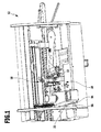
- FIG. 2 schematically illustrates an apparatus for the provision of molten adhesive, indicated generally by reference numeral 10.
- the device 10 forms an assembly of an edge banding machine 12, with which 16 edge material can be adhered to a narrow side 14 of a plate-shaped, continuously moving workpiece. On the narrow side 14, a molten adhesive is applied for this purpose.
- the edge banding machine 12 comprises an adhesive application unit 18, which in the FIGS. 2, 3 and 4 is shown schematically in the form of a glue application nozzle.
- adhesive application units are the expert, for example from the DE 40 12 726 A1 known.
- the molten adhesive is provided by the device 10. It comprises a first melting unit 20 and a second melting unit 22 and a valve unit 24.
- the structure of the first melting unit 20 and the valve unit 24 is in particular from Figures 3 and 4 clear.
- the first melting unit 20 comprises a first melting chamber 26 with a heatable melt insert 28. Via a feed opening 30, the first melting chamber 26 communicates with a funnel-shaped reservoir 32. In the reservoir, a first adhesive in the form of adhesive granules are introduced, which passes through the supply port 30 into the first melting chamber 26. Within the first melting chamber 26, the adhesive can be melted by means of the melting insert 28.
- a glue cartridge can be used, which is then melted in the first melting chamber 26 by means of the fuse link 28.
- the molten adhesive can be pressed by a first conveying device in the form of a delivery piston 34 displaceably mounted in the first melting chamber 26 in the direction of the valve unit 24 arranged on an end face of the melting chamber 26.
- the valve unit 24 is thermally conductively connected to the first melting chamber 26 and covers the first melting chamber from the front side. It comprises a first input 36, which connects directly to the first melting chamber 26, and a second input 38, to which a subsequently explained heatable connecting hose 40 is connected, and an output 42, to which a supply line 44 of the glue application unit 18 is connected.
- the second input 38 is permanently connected via a passage 46 of the valve unit 24 to the outlet 42 in fluid communication.
- the passage 46 opens an outgoing from the first input 36 input channel 48, in which a closing member the valve unit 24 is mounted in the form of a pivot pin 50.
- the pivot pin 50 has a through hole 52.
- the pivot pin 50 is between an in FIG. 3 illustrated blocking position and a in FIG. 4 shown release position pivoted back and forth.
- the through hole 50 is aligned in the blocking position perpendicular to the input channel 48, whereas in the in FIG. 4 shown release position is aligned with the input channel 48.
- the second pivoting unit 22 is slidably mounted on telescopic rails 54, 56 on a frame 58 of the device 10.
- the frame 58 forms part of the machine frame of the edge banding machine 12.
- the second melting unit 22 also has a heatable melting chamber and a conveying device for supplying the molten adhesive to the glue application unit 18.
- the second melting chamber and the conveying device of the second melting unit 22 are not shown in the drawing to obtain a better overview , However, such melting chambers and conveying devices are known per se to a person skilled in the art and therefore do not require any detailed explanation in the present case.
- the second melting aggregate 22 is in fluid communication with the first inlet 38 of the valve unit 24 via the heatable connecting hose 40, so that in the second melting chamber of the second melting aggregate 22 molten second adhesive can pass via the heatable connecting hose 40 to the second inlet 38 of the valve unit 24.
- the molten adhesive can then flow through the passage 46 and pass through the outlet 42 to the feed line 44 of the glue application unit 18.
- the second adhesive is preferably an air-curing thermoset used. If, instead of the second adhesive provided by the second melting aggregate 22, the first adhesive provided by the first melting aggregate 20 is to be used, then only the pivoting pin 50 has to be moved from its in FIG. 3 illustrated blocking position in his in FIG. 4 shown release position to be pivoted. Thereby, the flow connection between the first input 36 and the output 42 of the valve unit 24 is released, so that in the first melting chamber 26 molten first adhesive from the first input 36 via the input channel 48 and the end portion of the passage channel 46 to the output 42 and via this to the feed line 44 of the glue application unit 18 can get.
- the first molten adhesive is preferably a reversible meltable thermoplastic used.
- a rinsing agent can be introduced into the first melting chamber 26, with the aid of which the valve unit 24 and the glue application unit 18 can be rinsed after the end of an adhesive application process.
- the pivot pin 50 likewise assumes its release position, so that the flushing agent can reach the valve unit 24 via the first input 36.
- the user can change the adhesive used within a short time.
- adhesives of different colors can be used, so that it can change the color-matched adhesive within a short time when changing the adherend to the narrow side 14 edge material.
- thermosetting thermosetting plastic is used as the second adhesive
- the thermoset can come into contact with air after completion of the application process can be prevented in a simple manner by filling in the valve unit 24 via the first melting chamber 26 either rinsing agent or a molten thermoplastic as a first adhesive.
- thermoplastic forms a plug that prevents air access to the second input 38 and the connecting tube 40. This ensures that due to the lack of air contact that the thermoset located in the connecting tube 40 and the input portion of the passage channel 46 at a later date easily melted again and applied by the adhesive application unit 18 on the narrow side 14 of the workpiece 16.
Landscapes
- Life Sciences & Earth Sciences (AREA)
- Engineering & Computer Science (AREA)
- Mechanical Engineering (AREA)
- Wood Science & Technology (AREA)
- Forests & Forestry (AREA)
- Coating Apparatus (AREA)
- Physics & Mathematics (AREA)
- Thermal Sciences (AREA)
- Adhesives Or Adhesive Processes (AREA)
Applications Claiming Priority (1)
| Application Number | Priority Date | Filing Date | Title |
|---|---|---|---|
| DE200920016024 DE202009016024U1 (de) | 2009-11-18 | 2009-11-18 | Vorrichtung zum Bereitstellen von schmelzflüssigem Kleber |
Publications (2)
| Publication Number | Publication Date |
|---|---|
| EP2324931A2 true EP2324931A2 (fr) | 2011-05-25 |
| EP2324931A3 EP2324931A3 (fr) | 2011-12-07 |
Family
ID=41694305
Family Applications (1)
| Application Number | Title | Priority Date | Filing Date |
|---|---|---|---|
| EP10191217A Withdrawn EP2324931A3 (fr) | 2009-11-18 | 2010-11-15 | Dispositif de préparation de colles de fusion de fonderie |
Country Status (2)
| Country | Link |
|---|---|
| EP (1) | EP2324931A3 (fr) |
| DE (1) | DE202009016024U1 (fr) |
Cited By (1)
| Publication number | Priority date | Publication date | Assignee | Title |
|---|---|---|---|---|
| TWI784937B (zh) * | 2016-01-21 | 2022-12-01 | 荷蘭商梅耶博格荷蘭責任有限公司 | 用以處理基體之噴墨列印系統及方法 |
Citations (2)
| Publication number | Priority date | Publication date | Assignee | Title |
|---|---|---|---|---|
| DE4012726A1 (de) | 1990-04-21 | 1991-10-24 | Reich Spezialmaschinen Gmbh | Klebstoff-auftragsvorrichtung bei kantenanleimmaschinen |
| EP0750536B1 (fr) | 1994-03-15 | 1997-08-20 | REICH SPEZIALMASCHINEN GmbH | Machine a plaquer les chants avec dispositif de fraisage |
Family Cites Families (4)
| Publication number | Priority date | Publication date | Assignee | Title |
|---|---|---|---|---|
| DE3109369C2 (de) * | 1981-03-12 | 1984-01-12 | Reich Spezialmaschinen GmbH, 7440 Nürtingen | Schmelz- und Auftragsvorrichtung für Schmelzkleber |
| FR2519266B1 (fr) * | 1982-01-06 | 1986-12-19 | Pivaudran Sarl Ets G | Dispositif de melange et de distribution par doses d'un produit et application pour la distribution de colles, notamment a base de resine epoxyde |
| ITBO20010316A1 (it) * | 2001-05-18 | 2002-11-18 | Scm Group Spa | Gruppo di alimentazione colla, in particolare per macchine per la lavorazione di pannelli in legno |
| ITMO20060263A1 (it) * | 2006-08-28 | 2008-02-29 | Scm Group Spa | Apparato distributore di colla |
-
2009
- 2009-11-18 DE DE200920016024 patent/DE202009016024U1/de not_active Expired - Lifetime
-
2010
- 2010-11-15 EP EP10191217A patent/EP2324931A3/fr not_active Withdrawn
Patent Citations (2)
| Publication number | Priority date | Publication date | Assignee | Title |
|---|---|---|---|---|
| DE4012726A1 (de) | 1990-04-21 | 1991-10-24 | Reich Spezialmaschinen Gmbh | Klebstoff-auftragsvorrichtung bei kantenanleimmaschinen |
| EP0750536B1 (fr) | 1994-03-15 | 1997-08-20 | REICH SPEZIALMASCHINEN GmbH | Machine a plaquer les chants avec dispositif de fraisage |
Cited By (1)
| Publication number | Priority date | Publication date | Assignee | Title |
|---|---|---|---|---|
| TWI784937B (zh) * | 2016-01-21 | 2022-12-01 | 荷蘭商梅耶博格荷蘭責任有限公司 | 用以處理基體之噴墨列印系統及方法 |
Also Published As
| Publication number | Publication date |
|---|---|
| DE202009016024U1 (de) | 2010-02-18 |
| EP2324931A3 (fr) | 2011-12-07 |
Similar Documents
| Publication | Publication Date | Title |
|---|---|---|
| AT395825B (de) | Filtriervorrichtung fuer zu reinigende fluide | |
| DE3109369C2 (de) | Schmelz- und Auftragsvorrichtung für Schmelzkleber | |
| EP0754113B1 (fr) | Tete de filiere disposee a la sortie d'une extrudeuse | |
| DE10201830A1 (de) | Düsenende für eine Spritzgussdüse mit mehreren Spitzen | |
| EP0925904A1 (fr) | Procédé et dispositif pour changer le tamis d'un dispositif de filtration | |
| EP2205419A1 (fr) | Adaptateur pour canal et système de canal pour un adaptateur pour canal | |
| EP3216583A1 (fr) | Adaptateur de coextrusion | |
| DE10062659A1 (de) | Aufschäummittelbeladungs- und Mischvorrichtung | |
| EP2086743B1 (fr) | Dispositif de guidage commande d'une matiere plastique fondue | |
| EP2234786B1 (fr) | Unité d'injection à piston pour machine de moulage par injection | |
| DE3008779C2 (de) | Schmelz- und Auftragsvorrichtung für Schmelzkleber | |
| DE20104698U1 (de) | Leimbecken für eine Kantenleimmaschine | |
| EP0063244B1 (fr) | Dispositif d'application d'adhésifs | |
| DE2916070C2 (fr) | ||
| EP2305413B1 (fr) | Dispositif de soudage doté d'une tête d'électrode échangeable | |
| EP2324931A2 (fr) | Dispositif de préparation de colles de fusion de fonderie | |
| DE69114258T2 (de) | Düsevorrichtung zum spritzgiessen. | |
| DE69114163T2 (de) | Handhabung eines Mehrkomponentenklebers. | |
| DE20104697U1 (de) | Leimbecken für eine Kantenleimmaschine | |
| DE102011011215A1 (de) | Verfahren zum Verbinden und Verbindung eines ersten Werkstückes mit einem zweiten Werkstück | |
| DE69020936T2 (de) | Reaktionsspritzgussmaschine mit Verwendung mehrerer Reaktionsflüssigkeiten. | |
| EP1245366B1 (fr) | Mécanisme de blocage pour le contrôle du flux d'un milieu coulant | |
| DE202006019724U1 (de) | Vorrichtung mit Schlitzdüsenanordnung zum Abgeben von Fluid | |
| EP0061507B1 (fr) | Dispositif de fusion et d'application pour une colle fusible | |
| DE19956898C1 (de) | Adapterplatte für ein Spritzgiesswerkzeug einer Spritzgiessmaschine |
Legal Events
| Date | Code | Title | Description |
|---|---|---|---|
| PUAI | Public reference made under article 153(3) epc to a published international application that has entered the european phase |
Free format text: ORIGINAL CODE: 0009012 |
|
| AK | Designated contracting states |
Kind code of ref document: A2 Designated state(s): AL AT BE BG CH CY CZ DE DK EE ES FI FR GB GR HR HU IE IS IT LI LT LU LV MC MK MT NL NO PL PT RO RS SE SI SK SM TR |
|
| AX | Request for extension of the european patent |
Extension state: BA ME |
|
| PUAL | Search report despatched |
Free format text: ORIGINAL CODE: 0009013 |
|
| AK | Designated contracting states |
Kind code of ref document: A3 Designated state(s): AL AT BE BG CH CY CZ DE DK EE ES FI FR GB GR HR HU IE IS IT LI LT LU LV MC MK MT NL NO PL PT RO RS SE SI SK SM TR |
|
| AX | Request for extension of the european patent |
Extension state: BA ME |
|
| RIC1 | Information provided on ipc code assigned before grant |
Ipc: B05C 5/00 20060101ALN20111031BHEP Ipc: B29B 13/02 20060101ALI20111031BHEP Ipc: B05C 5/02 20060101ALI20111031BHEP Ipc: B05C 11/10 20060101AFI20111031BHEP |
|
| STAA | Information on the status of an ep patent application or granted ep patent |
Free format text: STATUS: THE APPLICATION IS DEEMED TO BE WITHDRAWN |
|
| 18D | Application deemed to be withdrawn |
Effective date: 20120609 |