EP2324953A2 - Affûteuse - Google Patents
Affûteuse Download PDFInfo
- Publication number
- EP2324953A2 EP2324953A2 EP20100190799 EP10190799A EP2324953A2 EP 2324953 A2 EP2324953 A2 EP 2324953A2 EP 20100190799 EP20100190799 EP 20100190799 EP 10190799 A EP10190799 A EP 10190799A EP 2324953 A2 EP2324953 A2 EP 2324953A2
- Authority
- EP
- European Patent Office
- Prior art keywords
- grinding
- motor
- blade
- grinding machine
- grinding wheel
- Prior art date
- Legal status (The legal status is an assumption and is not a legal conclusion. Google has not performed a legal analysis and makes no representation as to the accuracy of the status listed.)
- Granted
Links
Images



Classifications
-
- B—PERFORMING OPERATIONS; TRANSPORTING
- B24—GRINDING; POLISHING
- B24B—MACHINES, DEVICES, OR PROCESSES FOR GRINDING OR POLISHING; DRESSING OR CONDITIONING OF ABRADING SURFACES; FEEDING OF GRINDING, POLISHING, OR LAPPING AGENTS
- B24B3/00—Sharpening cutting edges, e.g. of tools; Accessories therefor, e.g. for holding the tools
- B24B3/36—Sharpening cutting edges, e.g. of tools; Accessories therefor, e.g. for holding the tools of cutting blades
- B24B3/54—Sharpening cutting edges, e.g. of tools; Accessories therefor, e.g. for holding the tools of cutting blades of hand or table knives
-
- B—PERFORMING OPERATIONS; TRANSPORTING
- B24—GRINDING; POLISHING
- B24B—MACHINES, DEVICES, OR PROCESSES FOR GRINDING OR POLISHING; DRESSING OR CONDITIONING OF ABRADING SURFACES; FEEDING OF GRINDING, POLISHING, OR LAPPING AGENTS
- B24B55/00—Safety devices for grinding or polishing machines; Accessories fitted to grinding or polishing machines for keeping tools or parts of the machine in good working condition
- B24B55/04—Protective covers for the grinding wheel
Definitions
- the invention relates to a grinding machine according to the preamble of claim 1.
- the grinding machine is particularly intended for grinding and sharpening the blade of a knife, but may also be used to grind the blade from other cutting tools such as hatchets or scissors, or daggers.
- the grinding machine can be used, for example, in food processing plants, for example in catering, meat, fish and vegetable processing plants.
- Knife grinding knives known in the market have a grinding wheel with a cylindrical grinding surface so that the blade of a knife can be slid over the grinding surface approximately parallel to the axis of rotation of the grinding wheel.
- These grinders have an electric motor with a motor housing and a motor shaft and often a polishing pad and / or a protective housing that covers at least large parts of the engine, the grinding wheel and the possible polishing pad.
- the grinding wheel is rotatably mounted with bearings about an axis of rotation and connected by a gear to the motor shaft.
- the axis of rotation of the grinding wheel is offset in such a way against the axis of rotation of the motor shaft, that the blade during grinding on the motor housing and on any Protective housing and / or can be pushed past the possible polishing pad.
- the invention has for its object to provide a grinding machine which avoids the disadvantages of the known grinding machines.
- the grinding machine should in particular be compact and inexpensive to produce.
- the grinding wheel is arranged according to the invention coaxial with the motor shaft and rotatably connected to the motor shaft. This allows a compact design.
- the grinding wheel can be supported by the bearings belonging to the motor, arranged in the motor housing, for supporting the motor shaft as well as the whole rotor of the motor, so that no additional bearings are required for supporting the grinding wheel.
- any existing polishing pad or possibly lapping disc Incidentally, of course, no transmission between the motor shaft and the grinding wheel and a possible polishing or lapping disc available.
- the inventive grinding machine is therefore also economical to produce.
- the inclined with respect to the axis of rotation of the grinding wheel, widening towards the motor housing, preferably approximately or exactly conical grinding surface allows a knife or other tool with a blade during grinding then approximately across the grinding surface and outside of the motor housing and a possible protective housing and / or a possible, also coaxial with the motor shaft polishing pad or possibly lapping disk move past, if the diameter of the grinding wheel is relatively small.
- grinding wheels may be rotated at most with a maximum permissible peripheral speed, so that the diameter of a grinding wheel may not exceed a specific maximum value for a given rotational speed of the grinding wheel.
- the invention also makes it possible to dimension the diameter of the grinding wheel without affecting the displaceability of the blade so small that the grinding wheel may be rotated without risk of damage directly to the speed of the motor.
- the grinding wheel can therefore be readily dimensioned, for example, so that it can be rotated directly with the speed of a single-phase electric asynchronous motor or possibly a three-phase asynchronous motor.
- the speed of the grinding wheel may then be at least 2500 revolutions per minute, preferably at most 3000 revolutions per minute and for example about 2700 to 2950 revolutions per minute when feeding the motor with alternating or three-phase current with a frequency of 50 Hz.
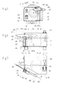
- the in the FIGS. 1 as well as 2 and partly in the Figures 3 and 4 shown grinder 1 has a protective housing 3 with a bottom 5 and a releasably secured to the latter guard 7.
- the bottom 5 has a flat plate, on the underside of feet 9 are attached.
- the protective hood 7 has a front wall 11, an end wall 13 opposite thereto, a cover wall 15 and two mutually opposite side walls 17 and 19.
- the protective housing 3 is generally approximately rectangular in plan.
- the side wall 19 has an adjacent to the end wall 13, parallel to the other side wall 17 side wall portion 21 and a side wall portion 23 whose main portion is inclined vertically and evenly and in plan from the wall portion 21 obliquely to the side wall 17.
- the grinding machine 1 has an electric motor 31 arranged in the protective housing 3, which is completely enclosed by the protective housing at least to a large extent and, for example, essentially - that is, apart from a few cooling holes and other holes.
- the motor 31 has a motor housing 33 with an im Generally cylindrical, for example, provided with cooling fins sheath and a rotor with a rotatably mounted with bearings in the motor housing motor shaft 35.
- the motor housing 33 is releasably secured with fastening means 37 and, for example, vibration damping attached to the bottom 5.
- the motor 31 is designed for example as a single-phase asynchronous motor, but could also consist of a three-phase asynchronous motor.
- the motor shaft 35 is rotatable about an approximately or exactly horizontal, parallel to the side wall 17 and the side wall portion 21 axis of rotation 39 and has closer to the side wall portion 23 and left in the FIGS. 1 to 3 located end of the motor housing 33 a protruding from this section.
- a grinding wheel 41 On the end portion sits a grinding wheel 41 and is releasably secured with fastening means 43, but rigidly and in particular rotationally fixed to the motor shaft.
- the fastening means 43 have, for example, a screw screwed into a threaded bore of the motor shaft.
- the grinding wheel 41 has a conical grinding surface 41a which widens toward the motor housing.
- the grinding surface 41a rotates during grinding, but defines a fixed, coincident with it, the rotation axis 39 enclosing the rotating surface, namely a conical surface, and a cone with a lying on the axis of rotation tip.
- the grinding surface 41a forms with the axis of rotation 39 an angle ⁇ , preferably at least 15 °, preferably at most 60 °, conveniently 20 ° to 40 ° and namely, for example, about 30 °.
- the diameter of the grinding wheel - ie the largest diameter of the conical grinding surface 41a - is preferably at least 100 mm, preferably at most 160 mm and for example 120 mm to 150 mm and is for example approximately the same size as the diameter of the jacket of the motor housing 33, but can also be a bit bigger or smaller than this.
- the grinding wheel 41 is provided on its front side, ie on its side facing away from the motor housing, with a recess 41b. This has, for example, an approximately flat base and a flared thereof away, conical side surface, the other, outer edge is at least approximately at the front edge of the conical grinding surface 41a.
- the grinding wheel has a metallic, for example made of aluminum base body and a grinding surface forming coating of an abrasive material. This contains, for example, boron nitride abrasive grains and a binder.
- a polishing pad 45 or lapping disc 45 is releasably, but rigidly and non-rotatably attached to that end portion of the motor shaft 35, for example, having a screw fastening means 47 which protrudes at the end facing away from the grinding wheel 41 of the motor housing 31 from this.
- the polishing or lapping disc 45 has an approximately cylindrical, for example, for polishing or lapping peripheral surface whose diameter is greater than the diameter of the jacket of the motor housing and the grinding wheel.
- the polishing or lapping disk points For example, interconnected layers of textile fabric, felt, leather or the like.
- the grinding wheel 41 and the polishing or lapping disk 45 are therefore rotatable coaxially with the motor shaft 35 and, like the latter, and the entire rotor of the motor 31 about the common axis of rotation 39, as described above.
- the belonging to the engine, arranged in the motor housing 33, for storing the motor shaft 35 serving bearings thus serve at the same time for storing the grinding wheel and the polishing or lapping disc.
- the protective cover 7 of the protective housing 3 has at the abutting edges of the front wall 11 and the side wall portion 23 in part also in Fig. 4
- the slot-shaped opening 51 is on the one side partly by an edge portion of the front wall 11 and on the other side partly by a fixed to the main plane portion of the side wall portion 23, of This outwardly projecting tabs 53 limited so that at the opening 51 is a more or less vertically extending, laterally limited by surfaces, outwardly open channel 55 results.
- a small peripheral portion of the grinding wheel 41 protrudes at the opening 51 through the protective housing out or at least into the channel 55, so that a peripheral portion of the grinding surface 41 a of the grinding wheel 41 from the outside, that is accessible from the environment of the protective housing ago.
- a protective element 57 made of sheet metal arranged at the upper end of the opening 51 covers a circumferential section of the grinding surface 41a therefrom.
- Support means 61 are arranged in the vicinity of the opening 51 in order to support and / or guide the blade of a knife to be ground in a manner described in greater detail during grinding.
- the support means 61 have a multi-part stop 63 with a holder 65, a head 67 and a screw 69.
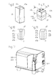
- the holder 65 of the stopper 63 is separately in Fig. 8 and consists of a substantially rectangular column with a square, approximately square plan.
- the holder 65 has two threaded holes at the lower end and is fastened to the base 5 with screws screwed into the latter in such a way that the holder is located at least partially in the lower part of the channel 55 and closes the opening 51 there more or less to the outside.
- the upper end surface of the holder is provided with a recess 65a with two straight edges parallel to each other.
- a vertical threaded bore 65b opens into the center of the recess 65a.
- the separately in the FIGS. 9, 10, 11 shown head 67 of the stopper 63 is also more or less parallelepipedic and has a continuous axial hole 67 a with a hole axis 71, which coincides with assembled hole with the hole axis of the threaded bore 65 b of the holder 65 and approximately or runs exactly vertically.
- the hole 67 a contains in the assembled state of the stopper part of the screw 69 and is provided at the upper end with an extension in which the screw head of the screw 69 is seated.
- the head 67 of the stop far at its lower end on a square end portion 67 b.
- the head also has at least an abutment surface, preferably at least two abutment surfaces, and for example three abutment surfaces 67c, 67d, 67e, each of which is formed by one of four side surfaces of the upper end portion of the head 67.
- the three abutment surfaces 67c, 67d, 67e are approximately or exactly planar and have different directions in axial sections through the hole axis 71.
- the abutment surface 67c is, for example, parallel to the hole axis and accordingly approximately or exactly vertical.
- the two other abutment surfaces 67d and 67e are inclined away from the holder 65 upwards to different degrees to the hole axis 71, so that they form with this and with a vertical plane different acute, for example, about 5 ° or about 10 ° amounting angle.
- the square end portion 67b of the head can with respect to the hole axis 71 selectively inserted in different rotational positions of the head fits snugly into the recess 61a of the holder 65 and secured with the screw 69 non-rotatably on the holder.
- the stop is designed and arranged such that, when the stop is assembled, depending on the rotational position of the head 67, one of the three stop surfaces 67c, 67d, 67e selectively faces the grinding surface 41a of the grinding wheel.
- the head 67 is provided under each of its abutment surfaces 67c, 67d, 67e with a flat surface 67f inclined downwards towards the hole axis 71, which is separated from the abutment surface above it by a straight edge 67g.
- the abutment surface 67c or 67d or 67e of the abutment 63 facing the grinding surface 41a defines, together with the peripheral portion facing it, the fixed surface of rotation defined by the grinding surface, ie Tapered surface, a gap 75 which narrows along said peripheral portion from top to bottom to the edge 67g out.
- the narrowest point of the gap 75 located at the edge 67g is dimensioned as narrow as possible and is, for example, approximately 0.1 mm to 0.5 mm wide.
- the edge 67g located below the stop surface facing the grinding surface 41a is preferably approximately at the level of the axis of rotation 39 of the motor shaft and the grinding wheel and / or, for example, slightly above the axis of rotation.
- the abutment is also arranged such that the edge 67g extends approximately horizontally and at least approximately or exactly parallel to a nearby surface line of the cone or conical surface defined by the rotating conical grinding surface 41a in operation.
- the edge may, for example, be slightly above a horizontal plane passing through the axis of rotation 39, exactly horizontal, and approximately or exactly parallel to that surface of the conical surface lying a little below the edge in the horizontal plane passing through the axis of rotation ,
- the straight edge line of the conical surface which is closest to the horizontal edge 67g does not run exactly parallel to the horizontal edge 67g but downwards against a horizontal plane to the rotation axis 39 and the tip of the cone defined by the grinding surface is inclined.
- the stop could possibly also be changed in such a way that the edge 67g lies somewhat further down in the horizontal plane passing through the axis of rotation 39 or indeed is above this horizontal plane, but slightly inclined to it so that it is approximately or exactly parallel to the closest lying on its surface line of the cone surface.
- the support means 61 still have one of the clearest in Fig. 4 apparent support member 77, which consists of an elongated, bent and / or bent piece of sheet metal.
- the upper end portion of the support member 77 is releasably secured with screws on the protective element 57 of the protective cover 7, so that it can be easily disassembled and replaced if necessary.
- the support member has a resilient tongue which extends away from the protective member 57 and from above approximately along a peripheral portion of the grinding surface 41a down to approximately the upper, further end of the gap 75 and, for example, a little into the gap.
- the protective housing contains in the Figures 2 and 3 visible, at least generally vertical inner walls 81 and 83.
- the inner wall 81 is located between the motor housing 33 and the grinding wheel 41, extends generally transverse to the axis of rotation 39 and has a hole according to Fig. 2 consists of a one side edge of the inner wall ago cut slot and is penetrated by the motor shaft 35.
- the other inner wall 83 extends on one side of the motor housing and the grinding wheel along the axis of rotation 39.
- the two inner walls border the grinding wheel containing portion of the interior of the protective housing 3 almost dust-tight against the remaining areas of the protective housing interior and in particular against the motor housing containing area of the protective housing interior from.
- the area of the interior of the protective housing containing the grinding wheel can be connected via a suction connection 85 of the grinding machine to a suction device formed, for example, by a vacuum cleaner for sucking off the grinding dust produced during grinding.
- One of the walls of the protective housing 3, namely preferably its top wall 15, is provided with a slot-shaped opening 87, through which a portion of the polishing or lapping disc 45 protrudes from the protective housing.
- a part of the opening 87 penetrating portion of the polishing or lapping disc is covered by a covering wall 89 connected to the top wall.
- the grinding machine still has a power connection 91 for the power supply of the motor and a switch 93 for switching the motor 31 on and off.
- a knife 101 has a blade 103 with a cutting edge 103a and a handle 105. For grinding and sharpening of the blade 103, it is inserted with the cutting edge 103a downwards from above against the direction of rotation of the grinding surface in the gap 75, so that a portion of Cut the Blade at a grinding point of the defined by the rotating grinding surface cone surface abuts the grinding surface and is ground by this.
- the cutting edge of a currently ground portion of the blade 103a is approximately at the edge 67g of the stop 63 facing the abrasive surface.
- the resilient tongue of the support member 77 supports a portion of the blade located above the blade during grinding and prevents it from jamming 77 covered peripheral portion of the grinding surface is touched by the blade or with one hand.
- the resilient tongue can also press the blade against the stop surface and thereby contribute to the fact that the blade rests well against the stop surface during grinding and is guided.
- the knife and its blade are thereby displaced approximately along an approximately straight displacement line 107 over the grinding surface.
- the displacement line 107 for example, runs approximately parallel to a surface line located near the grinding point of the conical surface defined by the rotating grinding surface and is approximately horizontal.
- the displacement line 107 may, for example, be approximately parallel to or parallel to the edge 67g facing the abrasive surface, through the narrowest point of the gap 75 and lie in an approximately or exactly horizontal plane that is slightly above the axis of rotation.
- the displacement line forms with the axis of rotation an angle ⁇ which is at least approximately and possibly exactly the same size as the angle ⁇ .
- the knife when moving along the displacement line 107 can also be pivoted a little bit around the grinding point up and down, so that the cutting edge abuts well at the grinding surface on the grinding surface.
- the translation line 107 is substantially - i. at least apart from its at the opening 51 of the protective housing 3 through the gap 75 extending portion - outside of the protective housing on this past.
- the displacement line 107 thus also extends, in particular outside the section of the protective housing containing the motor housing 33, beyond the section of the protective housing which is perpendicular to the axis of rotation 39 and past this section. Accordingly, the displacement line 107 extends beyond the motor housing 33 even past this.
- the displacement line also extends beyond the polishing or lapping disc 45 past this. This allows the blade of the knife to be moved over the grinding surface without obstructing the movement of the knife through the protective housing or the motor housing or the polishing or lapping disc.
- the blade of the knife is on the right side of the head 67 of the stopper 63.
- the blade can of course also be inserted into the gap 75 with the grip 105 to the left of the stop, so that both side surfaces of the blade's edge can be ground.
- the recess 41b carries the Grinding wheel in that the cutting edge 103a can be ground to approximately the handle.
- the abutment surface of the head 67 of the abutment 63 facing the grinding surface 41a forms an angle with a tangent to a circumferential section of the conical surface defined by the grinding surface. This angle is different, depending on which of the three abutment surfaces 67c, 67d, 67e faces the abrasive surface. By turning the head 67 so different angles between the stop surface and said tangent can be selected. The selected angle then determines the angle that form the two opposite side surfaces of the cutting edge after grinding together.
- the blade 103 After the blade 103 has been ground with the grinding wheel 41, it can still be polished or lapped with the polishing or lapping disk 45. Since this has a larger diameter than the grinding wheel 41 and protrudes beyond the flat main part of the top wall 15 of the protective housing 3, the blade can be moved during polishing or lapping approximately parallel to the rotation axis 39 on the cylindrical peripheral surface of the polishing or lapping without that this displacement is hindered by the grinding wheel or the motor or the protective housing or other parts of the grinding machine.
- the apparent grinding machine 201 has a protective housing 203, a motor 231 and a grinding wheel 241, but no polishing or lapping disc.
- the protective housing 203 may be in the axis of rotation parallel direction may be a little shorter than the protective housing 3 of the grinding machine 1.
- the grinding machine 201 is formed largely similar to the previously described grinding machine 1 except for the missing polishing or lapping disc and the somewhat shorter protective housing.
- the apparent grinding machine 301 has a motor 331 with a motor housing 333 and a base 335, which serves as a base for the whole grinding machine.
- the grinding machine 301 further has a grinding wheel 341 and a polishing or lapping disk 345, but no protective housing corresponding to the protective housing 3 of the grinding machine 1.
- the grinding machine 301 has two protective hoods 351 and 353 fastened to the motor housing, of which the protective hood 351 surrounds most of the grinding wheel 341 and the protective hood 353 encloses most of the polishing or lapping disk 345.
- the grinding machine 301 further has support means 361 with a stop 363 for supporting and possibly guiding a blade.
- the stopper 361 is attached to the guard 351 and has, for example, a head which has various abutment surfaces and can be fixed in different rotational positions on a serving as a holder part of the guard 351.
- the grinding machine 301 can be made substantially similar to the grinding machine 1.
- the grinding surface may be inclined only approximately conically and with respect to the axis of rotation of the grinding wheel be that their lying in axial sectional planes generatrices are slightly bent.
- the grinding surface and its generatrices should preferably be inclined outwards over the entire length in the direction of the motor housing away from the axis of rotation.
- the rotating during operation grinding surface then defines a fixed, the axis of rotation enclosing, coinciding with the grinding surface rotating surface with curved generatrices.
- the grinding surface may then possibly be formed so as to be parallel to the axis of rotation from a sectional plane parallel to, but for example, a horizontal, through which in FIG FIGS. 5 to 7 drawn displacement line 107 extending cutting plane is slightly offset from the axis of rotation is cut in straight lines.
Landscapes
- Engineering & Computer Science (AREA)
- Mechanical Engineering (AREA)
- Finish Polishing, Edge Sharpening, And Grinding By Specific Grinding Devices (AREA)
- Grinding-Machine Dressing And Accessory Apparatuses (AREA)
Applications Claiming Priority (1)
| Application Number | Priority Date | Filing Date | Title |
|---|---|---|---|
| CH01783/09A CH702291A2 (de) | 2009-11-19 | 2009-11-19 | Schleifmaschine. |
Publications (3)
| Publication Number | Publication Date |
|---|---|
| EP2324953A2 true EP2324953A2 (fr) | 2011-05-25 |
| EP2324953A3 EP2324953A3 (fr) | 2015-06-03 |
| EP2324953B1 EP2324953B1 (fr) | 2018-03-21 |
Family
ID=43798928
Family Applications (1)
| Application Number | Title | Priority Date | Filing Date |
|---|---|---|---|
| EP10190799.6A Active EP2324953B1 (fr) | 2009-11-19 | 2010-11-11 | Affûteuse |
Country Status (2)
| Country | Link |
|---|---|
| EP (1) | EP2324953B1 (fr) |
| CH (1) | CH702291A2 (fr) |
Cited By (3)
| Publication number | Priority date | Publication date | Assignee | Title |
|---|---|---|---|---|
| EP3718690A1 (fr) * | 2019-04-05 | 2020-10-07 | Tormek AB | Agencement de meulage d'outils tranchants |
| US11517998B2 (en) | 2019-04-05 | 2022-12-06 | Tormek Ab | Grinding jig for a blade tool |
| CN116529025A (zh) * | 2020-09-09 | 2023-08-01 | 霍尔1993有限责任公司 | 用于制作具有滚轮与手柄主体之间的最小间隙尺寸的辊式研磨机的方法 |
Families Citing this family (1)
| Publication number | Priority date | Publication date | Assignee | Title |
|---|---|---|---|---|
| CN118720973B (zh) * | 2024-09-04 | 2024-10-29 | 山西鸿辉机械制造股份有限公司 | 一种铸铁电机壳加工用打磨设备 |
Citations (2)
| Publication number | Priority date | Publication date | Assignee | Title |
|---|---|---|---|---|
| FR2611559A3 (fr) | 1987-03-05 | 1988-09-09 | Arcor Sarl | Procede d'affutage de couteaux, ciseaux et autres outils de coupe par des meules a sec |
| EP2030728A1 (fr) | 2007-08-28 | 2009-03-04 | Hans-Peter Zahnd | Dispositif de ponçage et ponceuse comportant un tel dispositif |
Family Cites Families (2)
| Publication number | Priority date | Publication date | Assignee | Title |
|---|---|---|---|---|
| US2638720A (en) * | 1951-01-02 | 1953-05-19 | Leo A Hoek | Cutlery sharpener |
| DE2140596A1 (de) * | 1971-08-13 | 1973-03-15 | Fritz Knecht | Halte- und fuehrungseinrichtung fuer eine schleifvorrichtung |
-
2009
- 2009-11-19 CH CH01783/09A patent/CH702291A2/de not_active Application Discontinuation
-
2010
- 2010-11-11 EP EP10190799.6A patent/EP2324953B1/fr active Active
Patent Citations (2)
| Publication number | Priority date | Publication date | Assignee | Title |
|---|---|---|---|---|
| FR2611559A3 (fr) | 1987-03-05 | 1988-09-09 | Arcor Sarl | Procede d'affutage de couteaux, ciseaux et autres outils de coupe par des meules a sec |
| EP2030728A1 (fr) | 2007-08-28 | 2009-03-04 | Hans-Peter Zahnd | Dispositif de ponçage et ponceuse comportant un tel dispositif |
Cited By (6)
| Publication number | Priority date | Publication date | Assignee | Title |
|---|---|---|---|---|
| EP3718690A1 (fr) * | 2019-04-05 | 2020-10-07 | Tormek AB | Agencement de meulage d'outils tranchants |
| US11517998B2 (en) | 2019-04-05 | 2022-12-06 | Tormek Ab | Grinding jig for a blade tool |
| US11628536B2 (en) | 2019-04-05 | 2023-04-18 | Tormek Ab | Arrangement for grinding edged tools |
| EP4265373A1 (fr) * | 2019-04-05 | 2023-10-25 | Tormek AB | Agencement pour meuler des outils à bords |
| US11833639B2 (en) | 2019-04-05 | 2023-12-05 | Tormek Ab | Arrangement for grinding edged tools |
| CN116529025A (zh) * | 2020-09-09 | 2023-08-01 | 霍尔1993有限责任公司 | 用于制作具有滚轮与手柄主体之间的最小间隙尺寸的辊式研磨机的方法 |
Also Published As
| Publication number | Publication date |
|---|---|
| EP2324953B1 (fr) | 2018-03-21 |
| CH702291A2 (de) | 2011-05-31 |
| EP2324953A3 (fr) | 2015-06-03 |
Similar Documents
| Publication | Publication Date | Title |
|---|---|---|
| EP0724857B1 (fr) | Couteaux pour un pied de mixage électrique | |
| EP2593233B1 (fr) | Porte-couteau pour dispositifs de broyage | |
| DE102019106758B4 (de) | Schneidvorrichtung; Separierer; Verfahren zum Separieren von Lebensmittelbestandteilen mittels eines Separierers | |
| EP2324953B1 (fr) | Affûteuse | |
| EP2877069B1 (fr) | Râpe circulaire | |
| EP2877070B1 (fr) | Rape circulaire | |
| EP0249840A2 (fr) | Dispositif pour le réglage automatique des couteaux d'un hache-viande | |
| EP2621320B1 (fr) | Lame de râpe réglable | |
| DE3012595A1 (de) | Messerkopf fuer kuttermesser | |
| DE102011105321B4 (de) | Trommelschneidemaschine und Messerkorb für eine solche Maschine | |
| EP1967271B1 (fr) | Lame de couteau | |
| EP1545282B1 (fr) | Outil destine a des appareils de cuisine | |
| WO2001000325A1 (fr) | Machine pour broyer une matiere coupee organique | |
| DE20216056U1 (de) | Vorrichtung zum Zerkleinern von Aufgabegut | |
| DE2814778B2 (de) | Zerkleinerungsmaschine für Schüttgüter | |
| DE102017223183B4 (de) | Bearbeitungsvorrichtung für die Zerkleinerung von Verarbeitungsgut | |
| DE1030218B (de) | Zerkleinerungsmaschine fuer Fleisch und aehnliche Produkte | |
| DE19905616B4 (de) | Kornmühle | |
| DE719800C (de) | Zerkleinerungsmaschine fuer vulkanisierten Gummi | |
| DE670606C (de) | Mahlgang oder Scheibenmuehle | |
| EP3503777B1 (fr) | Disque de traitement pourvu de zones d'outil sélectionnables | |
| DE202004018969U1 (de) | Spänebrecher | |
| DE13022C (de) | Schneide- und Reibemaschine für den Haushalt | |
| DE2802856B1 (de) | Schlägermühle mit Stauklotz | |
| CH290212A (de) | Mehrzweck-Speisezubereitungsmaschine. |
Legal Events
| Date | Code | Title | Description |
|---|---|---|---|
| PUAI | Public reference made under article 153(3) epc to a published international application that has entered the european phase |
Free format text: ORIGINAL CODE: 0009012 |
|
| AK | Designated contracting states |
Kind code of ref document: A2 Designated state(s): AL AT BE BG CH CY CZ DE DK EE ES FI FR GB GR HR HU IE IS IT LI LT LU LV MC MK MT NL NO PL PT RO RS SE SI SK SM TR |
|
| AX | Request for extension of the european patent |
Extension state: BA ME |
|
| PUAL | Search report despatched |
Free format text: ORIGINAL CODE: 0009013 |
|
| AK | Designated contracting states |
Kind code of ref document: A3 Designated state(s): AL AT BE BG CH CY CZ DE DK EE ES FI FR GB GR HR HU IE IS IT LI LT LU LV MC MK MT NL NO PL PT RO RS SE SI SK SM TR |
|
| AX | Request for extension of the european patent |
Extension state: BA ME |
|
| RIC1 | Information provided on ipc code assigned before grant |
Ipc: B24B 3/54 20060101AFI20150430BHEP Ipc: B24B 55/04 20060101ALI20150430BHEP |
|
| 17P | Request for examination filed |
Effective date: 20151203 |
|
| RBV | Designated contracting states (corrected) |
Designated state(s): AL AT BE BG CH CY CZ DE DK EE ES FI FR GB GR HR HU IE IS IT LI LT LU LV MC MK MT NL NO PL PT RO RS SE SI SK SM TR |
|
| STAA | Information on the status of an ep patent application or granted ep patent |
Free format text: STATUS: EXAMINATION IS IN PROGRESS |
|
| 17Q | First examination report despatched |
Effective date: 20170407 |
|
| GRAP | Despatch of communication of intention to grant a patent |
Free format text: ORIGINAL CODE: EPIDOSNIGR1 |
|
| STAA | Information on the status of an ep patent application or granted ep patent |
Free format text: STATUS: GRANT OF PATENT IS INTENDED |
|
| INTG | Intention to grant announced |
Effective date: 20171025 |
|
| GRAS | Grant fee paid |
Free format text: ORIGINAL CODE: EPIDOSNIGR3 |
|
| GRAA | (expected) grant |
Free format text: ORIGINAL CODE: 0009210 |
|
| STAA | Information on the status of an ep patent application or granted ep patent |
Free format text: STATUS: THE PATENT HAS BEEN GRANTED |
|
| AK | Designated contracting states |
Kind code of ref document: B1 Designated state(s): AL AT BE BG CH CY CZ DE DK EE ES FI FR GB GR HR HU IE IS IT LI LT LU LV MC MK MT NL NO PL PT RO RS SE SI SK SM TR |
|
| REG | Reference to a national code |
Ref country code: GB Ref legal event code: FG4D Free format text: NOT ENGLISH |
|
| REG | Reference to a national code |
Ref country code: CH Ref legal event code: EP |
|
| REG | Reference to a national code |
Ref country code: AT Ref legal event code: REF Ref document number: 980581 Country of ref document: AT Kind code of ref document: T Effective date: 20180415 |
|
| REG | Reference to a national code |
Ref country code: IE Ref legal event code: FG4D Free format text: LANGUAGE OF EP DOCUMENT: GERMAN |
|
| REG | Reference to a national code |
Ref country code: DE Ref legal event code: R096 Ref document number: 502010014781 Country of ref document: DE |
|
| REG | Reference to a national code |
Ref country code: NL Ref legal event code: MP Effective date: 20180321 |
|
| PG25 | Lapsed in a contracting state [announced via postgrant information from national office to epo] |
Ref country code: FI Free format text: LAPSE BECAUSE OF FAILURE TO SUBMIT A TRANSLATION OF THE DESCRIPTION OR TO PAY THE FEE WITHIN THE PRESCRIBED TIME-LIMIT Effective date: 20180321 Ref country code: NO Free format text: LAPSE BECAUSE OF FAILURE TO SUBMIT A TRANSLATION OF THE DESCRIPTION OR TO PAY THE FEE WITHIN THE PRESCRIBED TIME-LIMIT Effective date: 20180621 Ref country code: HR Free format text: LAPSE BECAUSE OF FAILURE TO SUBMIT A TRANSLATION OF THE DESCRIPTION OR TO PAY THE FEE WITHIN THE PRESCRIBED TIME-LIMIT Effective date: 20180321 Ref country code: LT Free format text: LAPSE BECAUSE OF FAILURE TO SUBMIT A TRANSLATION OF THE DESCRIPTION OR TO PAY THE FEE WITHIN THE PRESCRIBED TIME-LIMIT Effective date: 20180321 Ref country code: CY Free format text: LAPSE BECAUSE OF FAILURE TO SUBMIT A TRANSLATION OF THE DESCRIPTION OR TO PAY THE FEE WITHIN THE PRESCRIBED TIME-LIMIT Effective date: 20180321 |
|
| REG | Reference to a national code |
Ref country code: LT Ref legal event code: MG4D |
|
| PG25 | Lapsed in a contracting state [announced via postgrant information from national office to epo] |
Ref country code: BG Free format text: LAPSE BECAUSE OF FAILURE TO SUBMIT A TRANSLATION OF THE DESCRIPTION OR TO PAY THE FEE WITHIN THE PRESCRIBED TIME-LIMIT Effective date: 20180621 Ref country code: GR Free format text: LAPSE BECAUSE OF FAILURE TO SUBMIT A TRANSLATION OF THE DESCRIPTION OR TO PAY THE FEE WITHIN THE PRESCRIBED TIME-LIMIT Effective date: 20180622 Ref country code: LV Free format text: LAPSE BECAUSE OF FAILURE TO SUBMIT A TRANSLATION OF THE DESCRIPTION OR TO PAY THE FEE WITHIN THE PRESCRIBED TIME-LIMIT Effective date: 20180321 Ref country code: SE Free format text: LAPSE BECAUSE OF FAILURE TO SUBMIT A TRANSLATION OF THE DESCRIPTION OR TO PAY THE FEE WITHIN THE PRESCRIBED TIME-LIMIT Effective date: 20180321 Ref country code: RS Free format text: LAPSE BECAUSE OF FAILURE TO SUBMIT A TRANSLATION OF THE DESCRIPTION OR TO PAY THE FEE WITHIN THE PRESCRIBED TIME-LIMIT Effective date: 20180321 |
|
| PG25 | Lapsed in a contracting state [announced via postgrant information from national office to epo] |
Ref country code: MT Free format text: LAPSE BECAUSE OF FAILURE TO SUBMIT A TRANSLATION OF THE DESCRIPTION OR TO PAY THE FEE WITHIN THE PRESCRIBED TIME-LIMIT Effective date: 20180321 |
|
| PG25 | Lapsed in a contracting state [announced via postgrant information from national office to epo] |
Ref country code: RO Free format text: LAPSE BECAUSE OF FAILURE TO SUBMIT A TRANSLATION OF THE DESCRIPTION OR TO PAY THE FEE WITHIN THE PRESCRIBED TIME-LIMIT Effective date: 20180321 Ref country code: NL Free format text: LAPSE BECAUSE OF FAILURE TO SUBMIT A TRANSLATION OF THE DESCRIPTION OR TO PAY THE FEE WITHIN THE PRESCRIBED TIME-LIMIT Effective date: 20180321 Ref country code: EE Free format text: LAPSE BECAUSE OF FAILURE TO SUBMIT A TRANSLATION OF THE DESCRIPTION OR TO PAY THE FEE WITHIN THE PRESCRIBED TIME-LIMIT Effective date: 20180321 Ref country code: AL Free format text: LAPSE BECAUSE OF FAILURE TO SUBMIT A TRANSLATION OF THE DESCRIPTION OR TO PAY THE FEE WITHIN THE PRESCRIBED TIME-LIMIT Effective date: 20180321 Ref country code: ES Free format text: LAPSE BECAUSE OF FAILURE TO SUBMIT A TRANSLATION OF THE DESCRIPTION OR TO PAY THE FEE WITHIN THE PRESCRIBED TIME-LIMIT Effective date: 20180321 Ref country code: PL Free format text: LAPSE BECAUSE OF FAILURE TO SUBMIT A TRANSLATION OF THE DESCRIPTION OR TO PAY THE FEE WITHIN THE PRESCRIBED TIME-LIMIT Effective date: 20180321 |
|
| PG25 | Lapsed in a contracting state [announced via postgrant information from national office to epo] |
Ref country code: SK Free format text: LAPSE BECAUSE OF FAILURE TO SUBMIT A TRANSLATION OF THE DESCRIPTION OR TO PAY THE FEE WITHIN THE PRESCRIBED TIME-LIMIT Effective date: 20180321 Ref country code: CZ Free format text: LAPSE BECAUSE OF FAILURE TO SUBMIT A TRANSLATION OF THE DESCRIPTION OR TO PAY THE FEE WITHIN THE PRESCRIBED TIME-LIMIT Effective date: 20180321 Ref country code: SM Free format text: LAPSE BECAUSE OF FAILURE TO SUBMIT A TRANSLATION OF THE DESCRIPTION OR TO PAY THE FEE WITHIN THE PRESCRIBED TIME-LIMIT Effective date: 20180321 |
|
| PG25 | Lapsed in a contracting state [announced via postgrant information from national office to epo] |
Ref country code: PT Free format text: LAPSE BECAUSE OF FAILURE TO SUBMIT A TRANSLATION OF THE DESCRIPTION OR TO PAY THE FEE WITHIN THE PRESCRIBED TIME-LIMIT Effective date: 20180723 |
|
| REG | Reference to a national code |
Ref country code: DE Ref legal event code: R097 Ref document number: 502010014781 Country of ref document: DE |
|
| PLBE | No opposition filed within time limit |
Free format text: ORIGINAL CODE: 0009261 |
|
| STAA | Information on the status of an ep patent application or granted ep patent |
Free format text: STATUS: NO OPPOSITION FILED WITHIN TIME LIMIT |
|
| PG25 | Lapsed in a contracting state [announced via postgrant information from national office to epo] |
Ref country code: DK Free format text: LAPSE BECAUSE OF FAILURE TO SUBMIT A TRANSLATION OF THE DESCRIPTION OR TO PAY THE FEE WITHIN THE PRESCRIBED TIME-LIMIT Effective date: 20180321 |
|
| 26N | No opposition filed |
Effective date: 20190102 |
|
| PG25 | Lapsed in a contracting state [announced via postgrant information from national office to epo] |
Ref country code: SI Free format text: LAPSE BECAUSE OF FAILURE TO SUBMIT A TRANSLATION OF THE DESCRIPTION OR TO PAY THE FEE WITHIN THE PRESCRIBED TIME-LIMIT Effective date: 20180321 |
|
| REG | Reference to a national code |
Ref country code: CH Ref legal event code: NV Representative=s name: BRAUNPAT BRAUN EDER AG, CH |
|
| GBPC | Gb: european patent ceased through non-payment of renewal fee |
Effective date: 20181111 |
|
| PG25 | Lapsed in a contracting state [announced via postgrant information from national office to epo] |
Ref country code: LU Free format text: LAPSE BECAUSE OF NON-PAYMENT OF DUE FEES Effective date: 20181111 Ref country code: MC Free format text: LAPSE BECAUSE OF FAILURE TO SUBMIT A TRANSLATION OF THE DESCRIPTION OR TO PAY THE FEE WITHIN THE PRESCRIBED TIME-LIMIT Effective date: 20180321 |
|
| REG | Reference to a national code |
Ref country code: IE Ref legal event code: MM4A |
|
| PG25 | Lapsed in a contracting state [announced via postgrant information from national office to epo] |
Ref country code: IE Free format text: LAPSE BECAUSE OF NON-PAYMENT OF DUE FEES Effective date: 20181111 |
|
| PG25 | Lapsed in a contracting state [announced via postgrant information from national office to epo] |
Ref country code: GB Free format text: LAPSE BECAUSE OF NON-PAYMENT OF DUE FEES Effective date: 20181111 |
|
| PG25 | Lapsed in a contracting state [announced via postgrant information from national office to epo] |
Ref country code: TR Free format text: LAPSE BECAUSE OF FAILURE TO SUBMIT A TRANSLATION OF THE DESCRIPTION OR TO PAY THE FEE WITHIN THE PRESCRIBED TIME-LIMIT Effective date: 20180321 |
|
| PG25 | Lapsed in a contracting state [announced via postgrant information from national office to epo] |
Ref country code: MK Free format text: LAPSE BECAUSE OF NON-PAYMENT OF DUE FEES Effective date: 20180321 Ref country code: HU Free format text: LAPSE BECAUSE OF FAILURE TO SUBMIT A TRANSLATION OF THE DESCRIPTION OR TO PAY THE FEE WITHIN THE PRESCRIBED TIME-LIMIT; INVALID AB INITIO Effective date: 20101111 |
|
| PG25 | Lapsed in a contracting state [announced via postgrant information from national office to epo] |
Ref country code: IS Free format text: LAPSE BECAUSE OF FAILURE TO SUBMIT A TRANSLATION OF THE DESCRIPTION OR TO PAY THE FEE WITHIN THE PRESCRIBED TIME-LIMIT Effective date: 20180721 |
|
| REG | Reference to a national code |
Ref country code: CH Ref legal event code: U11 Free format text: ST27 STATUS EVENT CODE: U-0-0-U10-U11 (AS PROVIDED BY THE NATIONAL OFFICE) Effective date: 20251201 |
|
| PGFP | Annual fee paid to national office [announced via postgrant information from national office to epo] |
Ref country code: DE Payment date: 20251119 Year of fee payment: 16 |
|
| PGFP | Annual fee paid to national office [announced via postgrant information from national office to epo] |
Ref country code: AT Payment date: 20251120 Year of fee payment: 16 |
|
| PGFP | Annual fee paid to national office [announced via postgrant information from national office to epo] |
Ref country code: IT Payment date: 20251125 Year of fee payment: 16 |
|
| PGFP | Annual fee paid to national office [announced via postgrant information from national office to epo] |
Ref country code: FR Payment date: 20251124 Year of fee payment: 16 |
|
| PGFP | Annual fee paid to national office [announced via postgrant information from national office to epo] |
Ref country code: BE Payment date: 20251119 Year of fee payment: 16 |
|
| PGFP | Annual fee paid to national office [announced via postgrant information from national office to epo] |
Ref country code: CH Payment date: 20251201 Year of fee payment: 16 |