EP2325071A2 - Anordnung zum Laden der Batterie von Elektrofahrrädern - Google Patents
Anordnung zum Laden der Batterie von Elektrofahrrädern Download PDFInfo
- Publication number
- EP2325071A2 EP2325071A2 EP10450177A EP10450177A EP2325071A2 EP 2325071 A2 EP2325071 A2 EP 2325071A2 EP 10450177 A EP10450177 A EP 10450177A EP 10450177 A EP10450177 A EP 10450177A EP 2325071 A2 EP2325071 A2 EP 2325071A2
- Authority
- EP
- European Patent Office
- Prior art keywords
- charging
- holder
- contact
- hub
- contacts
- Prior art date
- Legal status (The legal status is an assumption and is not a legal conclusion. Google has not performed a legal analysis and makes no representation as to the accuracy of the status listed.)
- Granted
Links
Images


Classifications
-
- B—PERFORMING OPERATIONS; TRANSPORTING
- B62—LAND VEHICLES FOR TRAVELLING OTHERWISE THAN ON RAILS
- B62H—CYCLE STANDS; SUPPORTS OR HOLDERS FOR PARKING OR STORING CYCLES; APPLIANCES PREVENTING OR INDICATING UNAUTHORIZED USE OR THEFT OF CYCLES; LOCKS INTEGRAL WITH CYCLES; DEVICES FOR LEARNING TO RIDE CYCLES
- B62H3/00—Separate supports or holders for parking or storing cycles
- B62H3/04—Separate supports or holders for parking or storing cycles involving forked supports of brackets for holding a wheel
-
- B—PERFORMING OPERATIONS; TRANSPORTING
- B60—VEHICLES IN GENERAL
- B60L—PROPULSION OF ELECTRICALLY-PROPELLED VEHICLES; SUPPLYING ELECTRIC POWER FOR AUXILIARY EQUIPMENT OF ELECTRICALLY-PROPELLED VEHICLES; ELECTRODYNAMIC BRAKE SYSTEMS FOR VEHICLES IN GENERAL; MAGNETIC SUSPENSION OR LEVITATION FOR VEHICLES; MONITORING OPERATING VARIABLES OF ELECTRICALLY-PROPELLED VEHICLES; ELECTRIC SAFETY DEVICES FOR ELECTRICALLY-PROPELLED VEHICLES
- B60L50/00—Electric propulsion with power supplied within the vehicle
- B60L50/20—Electric propulsion with power supplied within the vehicle using propulsion power generated by humans or animals
-
- B—PERFORMING OPERATIONS; TRANSPORTING
- B60—VEHICLES IN GENERAL
- B60L—PROPULSION OF ELECTRICALLY-PROPELLED VEHICLES; SUPPLYING ELECTRIC POWER FOR AUXILIARY EQUIPMENT OF ELECTRICALLY-PROPELLED VEHICLES; ELECTRODYNAMIC BRAKE SYSTEMS FOR VEHICLES IN GENERAL; MAGNETIC SUSPENSION OR LEVITATION FOR VEHICLES; MONITORING OPERATING VARIABLES OF ELECTRICALLY-PROPELLED VEHICLES; ELECTRIC SAFETY DEVICES FOR ELECTRICALLY-PROPELLED VEHICLES
- B60L53/00—Methods of charging batteries, specially adapted for electric vehicles; Charging stations or on-board charging equipment therefor; Exchange of energy storage elements in electric vehicles
- B60L53/10—Methods of charging batteries, specially adapted for electric vehicles; Charging stations or on-board charging equipment therefor; Exchange of energy storage elements in electric vehicles characterised by the energy transfer between the charging station and the vehicle
- B60L53/14—Conductive energy transfer
-
- B—PERFORMING OPERATIONS; TRANSPORTING
- B60—VEHICLES IN GENERAL
- B60L—PROPULSION OF ELECTRICALLY-PROPELLED VEHICLES; SUPPLYING ELECTRIC POWER FOR AUXILIARY EQUIPMENT OF ELECTRICALLY-PROPELLED VEHICLES; ELECTRODYNAMIC BRAKE SYSTEMS FOR VEHICLES IN GENERAL; MAGNETIC SUSPENSION OR LEVITATION FOR VEHICLES; MONITORING OPERATING VARIABLES OF ELECTRICALLY-PROPELLED VEHICLES; ELECTRIC SAFETY DEVICES FOR ELECTRICALLY-PROPELLED VEHICLES
- B60L53/00—Methods of charging batteries, specially adapted for electric vehicles; Charging stations or on-board charging equipment therefor; Exchange of energy storage elements in electric vehicles
- B60L53/30—Constructional details of charging stations
-
- B—PERFORMING OPERATIONS; TRANSPORTING
- B60—VEHICLES IN GENERAL
- B60L—PROPULSION OF ELECTRICALLY-PROPELLED VEHICLES; SUPPLYING ELECTRIC POWER FOR AUXILIARY EQUIPMENT OF ELECTRICALLY-PROPELLED VEHICLES; ELECTRODYNAMIC BRAKE SYSTEMS FOR VEHICLES IN GENERAL; MAGNETIC SUSPENSION OR LEVITATION FOR VEHICLES; MONITORING OPERATING VARIABLES OF ELECTRICALLY-PROPELLED VEHICLES; ELECTRIC SAFETY DEVICES FOR ELECTRICALLY-PROPELLED VEHICLES
- B60L53/00—Methods of charging batteries, specially adapted for electric vehicles; Charging stations or on-board charging equipment therefor; Exchange of energy storage elements in electric vehicles
- B60L53/30—Constructional details of charging stations
- B60L53/35—Means for automatic or assisted adjustment of the relative position of charging devices and vehicles
- B60L53/36—Means for automatic or assisted adjustment of the relative position of charging devices and vehicles by positioning the vehicle
-
- B—PERFORMING OPERATIONS; TRANSPORTING
- B62—LAND VEHICLES FOR TRAVELLING OTHERWISE THAN ON RAILS
- B62M—RIDER PROPULSION OF WHEELED VEHICLES OR SLEDGES; POWERED PROPULSION OF SLEDGES OR SINGLE-TRACK CYCLES; TRANSMISSIONS SPECIALLY ADAPTED FOR SUCH VEHICLES
- B62M6/00—Rider propulsion of wheeled vehicles with additional source of power, e.g. combustion engine or electric motor
- B62M6/80—Accessories, e.g. power sources; Arrangements thereof
-
- B—PERFORMING OPERATIONS; TRANSPORTING
- B60—VEHICLES IN GENERAL
- B60L—PROPULSION OF ELECTRICALLY-PROPELLED VEHICLES; SUPPLYING ELECTRIC POWER FOR AUXILIARY EQUIPMENT OF ELECTRICALLY-PROPELLED VEHICLES; ELECTRODYNAMIC BRAKE SYSTEMS FOR VEHICLES IN GENERAL; MAGNETIC SUSPENSION OR LEVITATION FOR VEHICLES; MONITORING OPERATING VARIABLES OF ELECTRICALLY-PROPELLED VEHICLES; ELECTRIC SAFETY DEVICES FOR ELECTRICALLY-PROPELLED VEHICLES
- B60L2200/00—Type of vehicles
- B60L2200/12—Bikes
-
- Y—GENERAL TAGGING OF NEW TECHNOLOGICAL DEVELOPMENTS; GENERAL TAGGING OF CROSS-SECTIONAL TECHNOLOGIES SPANNING OVER SEVERAL SECTIONS OF THE IPC; TECHNICAL SUBJECTS COVERED BY FORMER USPC CROSS-REFERENCE ART COLLECTIONS [XRACs] AND DIGESTS
- Y02—TECHNOLOGIES OR APPLICATIONS FOR MITIGATION OR ADAPTATION AGAINST CLIMATE CHANGE
- Y02T—CLIMATE CHANGE MITIGATION TECHNOLOGIES RELATED TO TRANSPORTATION
- Y02T10/00—Road transport of goods or passengers
- Y02T10/60—Other road transportation technologies with climate change mitigation effect
- Y02T10/70—Energy storage systems for electromobility, e.g. batteries
-
- Y—GENERAL TAGGING OF NEW TECHNOLOGICAL DEVELOPMENTS; GENERAL TAGGING OF CROSS-SECTIONAL TECHNOLOGIES SPANNING OVER SEVERAL SECTIONS OF THE IPC; TECHNICAL SUBJECTS COVERED BY FORMER USPC CROSS-REFERENCE ART COLLECTIONS [XRACs] AND DIGESTS
- Y02—TECHNOLOGIES OR APPLICATIONS FOR MITIGATION OR ADAPTATION AGAINST CLIMATE CHANGE
- Y02T—CLIMATE CHANGE MITIGATION TECHNOLOGIES RELATED TO TRANSPORTATION
- Y02T10/00—Road transport of goods or passengers
- Y02T10/60—Other road transportation technologies with climate change mitigation effect
- Y02T10/7072—Electromobility specific charging systems or methods for batteries, ultracapacitors, supercapacitors or double-layer capacitors
-
- Y—GENERAL TAGGING OF NEW TECHNOLOGICAL DEVELOPMENTS; GENERAL TAGGING OF CROSS-SECTIONAL TECHNOLOGIES SPANNING OVER SEVERAL SECTIONS OF THE IPC; TECHNICAL SUBJECTS COVERED BY FORMER USPC CROSS-REFERENCE ART COLLECTIONS [XRACs] AND DIGESTS
- Y02—TECHNOLOGIES OR APPLICATIONS FOR MITIGATION OR ADAPTATION AGAINST CLIMATE CHANGE
- Y02T—CLIMATE CHANGE MITIGATION TECHNOLOGIES RELATED TO TRANSPORTATION
- Y02T90/00—Enabling technologies or technologies with a potential or indirect contribution to GHG emissions mitigation
- Y02T90/10—Technologies relating to charging of electric vehicles
- Y02T90/12—Electric charging stations
-
- Y—GENERAL TAGGING OF NEW TECHNOLOGICAL DEVELOPMENTS; GENERAL TAGGING OF CROSS-SECTIONAL TECHNOLOGIES SPANNING OVER SEVERAL SECTIONS OF THE IPC; TECHNICAL SUBJECTS COVERED BY FORMER USPC CROSS-REFERENCE ART COLLECTIONS [XRACs] AND DIGESTS
- Y02—TECHNOLOGIES OR APPLICATIONS FOR MITIGATION OR ADAPTATION AGAINST CLIMATE CHANGE
- Y02T—CLIMATE CHANGE MITIGATION TECHNOLOGIES RELATED TO TRANSPORTATION
- Y02T90/00—Enabling technologies or technologies with a potential or indirect contribution to GHG emissions mitigation
- Y02T90/10—Technologies relating to charging of electric vehicles
- Y02T90/14—Plug-in electric vehicles
Definitions
- the invention relates to an arrangement for charging the battery of electric bicycles and the like single-track electric vehicles, with a stationary charger whose arranged on a holder charging contacts are electrically connected to contact elements on the electric vehicle, wherein the contact elements on the hub of a wheel of the electric vehicle and the Charging contacts are arranged in the holder at the bottom of recesses formed for inserting the ends of a hub.
- Charging the batteries of electric vehicles is often done by connecting the charger to the battery via a cable. This requires on the one hand an often undesirable manual activity, on the other hand can be easily forgotten to charge the battery.
- the extended wheel hub is placed in a trough and thus made an electrical connection only by gravity.
- Such a contact is extremely unreliable, in particular, the trough or the extended hub may be dirty and this dirt can not always be displaced only by gravity, to make the electrical connection.
- the invention has set itself the goal of creating an arrangement with which the charging of the battery when parking the electric vehicle is safer.
- a charging of the battery is automatically made possible when inserting or setting the electric bicycle in the holder.
- charging may be e.g. be made dependent on the payment, cash or credit cards, or at known ATMs.
- swiveling body or sliding body are arranged in the recesses and in the way of sliding or pivoting movement of this body is arranged a power supply switching from the charger switch.
- the charging contacts are only supplied with power when an electric bicycle is in the holder.
- the charging contacts are formed as approximately U-shaped springs for receiving the contact elements.
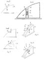
- a holder 1 is provided, which has two spaced about a wheel width from one another plates 2 and 3. Between the plates 2 and 3, the wheel of an electric bicycle is inserted, which is held by it.
- Fig. 1 to 3 are in the plates 2, 3 recesses V arranged in which pivoting bodies 9 are pivotally mounted. At the bottom of the recess V charging contacts 10 are arranged.
- the extended, provided with the contact elements hub of a wheel are used.
- the swivel body 9 is thereby pivoted against the force of the spring 12, wherein the contact 11 by contact with its mating contact 11 'closes the power supply from the charger.
- a recess V is provided in the plates 2 and 3, in which the elongated hub, which is provided with the contact elements, is inserted.
- the Fig. 6 shown on a larger scale.
- a sliding body 13 is against the force of a spring 14 downwardly displaceable.
- the charging contact 15 is arranged, which is electrically connected to a contact 16 provided on an extension of the sliding body 13.
- the charging contacts 20 are formed as approximately U-shaped springs, wherein in the "U” provided with the Maiselemehten hub of a wheel can be inserted.
- the springs 20 are inserted in recesses V of the plates 2, 3.
- FIGS. 10 to 12 is similar to the embodiment of the FIGS. 1 to 3 , Again, a pivoting body 21 is provided, which closes the power supply from the charger to the charging contact 24 in the recess V via a contact 22 when inserting the hub of the wheel in the recess V of the plates 2 and 3.
- the entire holder is against the force of springs 25 downwardly displaceable.
- the arranged in a recess V charging contact 27 receives when inserting the hub of a wheel in the recess V and the resulting lowering of the plates 2 and 3 of the holder 1 via a contact 28, which is then in contact with its mating contact 28 ', current from Charger.
- the holder can have other shapes, the charger can be installed in the holder or connected externally.
- the current consumption at the wheel can also be unilateral, e.g. on one side two contacts and more.
- the arrangement can also be equipped with an additional power button, charging lamps, a timer or an automatic switch-off.
- the holders may also be formed in series for a plurality of wheels, e.g. through modules that can be infected again and again.
Landscapes
- Engineering & Computer Science (AREA)
- Mechanical Engineering (AREA)
- Transportation (AREA)
- Power Engineering (AREA)
- Chemical & Material Sciences (AREA)
- Combustion & Propulsion (AREA)
- Charge And Discharge Circuits For Batteries Or The Like (AREA)
- Electric Propulsion And Braking For Vehicles (AREA)
Abstract
Description
- Die Erfindung bezieht sich auf eine Anordnung zum Laden der Batterie von Elektrofahrrädem und dergleichen einspurigen Elektrofahrzeugen, mit einem stationären Ladegerät, dessen an einem Halter angeordnete Ladekontakte mit Kontaktelementen am Elektrofahrzeug elektrisch zu verbinden sind, wobei die Kontaktelemente an der Nabe eines Rades des Elektrofahrzeuges und die Ladekontakte im Halter am Grund von zum Einlegen der Enden einer Nabe ausgebildeten Vertiefungen angeordnet sind.
- Das Laden der Batterien von Elektrofahrzeugen erfolgt oft dadurch, dass das Ladegerät über ein Kabel mit der Batterie verbunden wird. Dies erfordert einerseits eine oft nicht erwünschte manuelle Tätigkeit, andererseits kann sehr leicht auf das Laden der Batterie vergessen werden.
- In der
EP 2 168 848 A1 ist eine Anordnung der eingangs genannten Art beschrieben. Gemäß der dort beschriebenen Einrichtung wird die verlängerte Radnabe in eine Mulde gelegt und so bloß durch die Schwerkraft eine elektrische Verbindung hergestellt. Ein derartiger Kontakt ist äußerst unzuverlässig, insbesondere kann die Mulde oder auch die verlängerte Nabe verschmutzt sein und dieser Schmutz kann bloß durch die Schwerkraft nicht immer verdrängt werden, um die elektrische Verbindung herzustellen. - Die Erfindung hat es sich zum Ziel gesetzt eine Anordnung zu schaffen, mit der das Laden der Batterie beim Abstellen des Elektrofahrzeuges sicherer erfolgt.
- Erreicht wird dies bei einer Anordnung der eingangs genannten Art dadurch, dass die Ladekontakte als federnde Kontakte ausgebildet sind. Durch die Federkraft wird die elektrische Verbindung weitaus sicherer hergestellt als bei der bekannten Einrichtung.
- Federbelastete Kontakte sind an sich bekannt. So wird in der Druckschrift
CN000201227988Y - Bei einer erfindungsgemäßen Anordnung wird beim Einschieben oder Einstellen des Elektrofahrrades in den Halter automatisch ein Laden der Batterie ermöglicht. Ein solches Laden kann allerdings z.B. von der Bezahlung, Bar oder durch Kreditkarten, oder bei bekannten Geldautomaten, abhängig gemacht werden.
- Bei einer erfindungsgemäßen Anordnung ist es möglich, dass in den Vertiefungen Schwenkkörper oder Schiebekörper angeordnet sind und im Wege der Schiebe- oder Schwenkbewegung dieser Körper ein die Stromzuführung vom Ladegerät schaltender Schalter angeordnet ist. Bei einer solchen Anordnung werden die Ladekontakte nur dann mit Strom versorgt, wenn sich ein Elektrofahrrad im Halter befindet.
- Im Rahmen der Erfindung ist es aber auch möglich, dass die Ladekontakte als annähernd U-förmige Federn zur Aufnahme der Kontaktelemente ausgebildet sind.
- Es wird auch eine erfindungsgemäße Anordnung vorgeschlagen, bei der der Halter entgegen der Kraft von Federn verschiebbar gelagert ist und im Wege der Schiebebewegung ein die Stromzuführung vom Ladegerät schaltender Schalter angeordnet ist. Bei dieser Anordnung wird demnach die Verschiebung der Ladekontakte durch Verschiebung des gesamten Halters erreicht.
- Nachstehend ist die Erfindung anhand von in den Zeichnungen dargestellten Ausführungsbeispielen näher beschrieben, ohne auf diese Beispiele beschränkt zu sein. Dabei zeigen:
- Die Fig. 1 bis 3
- in schaubildlicher Ansicht, in Seitenansicht und im Schnitt einen erfindungsgemäß ausgebildeten Halter;
- die Fig. 4 bis 6
- in ähnlicher Darstellungsweise eine weitere Ausführungsform eines erfindungsgemäß ausgestalteten Halters;
- Bei den Ausführungsformen nach den
Figuren 1 bis 15 ist jeweils ein Halter 1 vorgesehen, der zwei im Abstand etwa einer Radbreite voneinander stehende Platten 2 und 3 aufweist. Zwischen die Platten 2 und 3 ist das Rad eines Elektrofahrrades einschiebbar, das dadurch gehalten wird. - Das Rad mit seiner Nabe ist aus Gründen der Übersichtlichkeit in den Zeichnungen nicht dargestellt.
- Gemäß den
Fig. 1 bis 3 sind in den Platten 2, 3 Vertiefungen V angeordnet, in denen Schwenkkörper 9 schwenkbar gelagert sind. Am Grund der Vertiefung V sind Ladekontakte 10 angeordnet. - An den Schwenkkörpern 9 sind Kontakte 11 eines die Stromzuführung vom Ladegerät schaltenden Schalters vorgesehen. Eine Feder 12 drängt den Schwenkkörper 9 nach außen.
- In die Vertiefungen V werden die verlängerten, mit den Kontaktelementen versehenen Naben eines Rades eingesetzt. Der Schwenkkörper 9 wird dadurch entgegen der Kraft der Feder 12 verschwenkt, wobei der Kontakt 11 durch Berührung mit seinem Gegenkontakt 11' die Stromzuführung vom Ladegerät schließt.
- Auch bei der Ausführungsform nach den
Figuren 4 bis 6 ist eine Vertiefung V in den Platten 2 und 3 vorgesehen, in welche die verlängerte Nabe, welche mit den Kontaktelementen versehen ist, eingelegt wird. Zur Erhöhung der Übersichtlichkeit ist dieFig. 6 in einem größeren Maßstab dargestellt. - Ein Schiebekörper 13 ist entgegen der Kraft einer Feder 14 nach unten verschiebbar. Am Grund der Vertiefung ist der Ladekontakt 15 angeordnet, der elektrisch mit einem an einem Fortsatz des Schiebekörpers 13 vorgesehenen Kontakt 16 verbunden ist.
- Beim Einsetzen der verlängerten Nabe in die Vertiefung V wird der Schiebekörper 13 nach unten verschoben und der Kontakt 16 kommt zur Anlage an seinem Gegenkontakt 16', wodurch die Verbindung mit dem Ladegerät hergestellt ist.
- Bei der Ausführungsform nach den
Figuren 7 bis 9 sind die Ladekontakte 20 als annähernd U-förmige Federn ausgebildet, wobei in das "U" die mit den Kontaktelemehten versehene Nabe eines Rades eingeschoben werden kann. Die Federn 20 sind in Vertiefungen V der Platten 2, 3 eingesetzt. - Die Variante nach den
Figuren 10 bis 12 ähnelt der Ausführungsform nach denFiguren 1 bis 3 . Auch hier ist ein Schwenkkörper 21 vorgesehen, der über einen Kontakt 22 beim Einlegen der Nabe des Rades in die Vertiefung V der Platten 2 und 3 die Stromzuführung vom Ladegerät zum Ladekontakt 24 in der Vertiefung V schließt. - Bei der Variante nach den
Figuren 13 bis 15 ist der gesamte Halter entgegen der Kraft von Federn 25 nach unten verschiebbar. Der in einer Vertiefung V angeordnete Ladekontakt 27 erhält beim Einlegen der Nabe eines Rades in die Vertiefung V und dem daraus erfolgten Absenken der Platten 2 und 3 des Halters 1 über einen Kontakt 28, der dann mit seinem Gegenkontakt 28' in Berührung ist, Strom vom Ladegerät. - Im Rahmen der Erfindung sind zahlreiche Abänderungen möglich. So kann der Halter auch andere Formen haben, das Ladegerät kann im Halter eingebaut sein oder auch extern angeschlossen werden. Die Stromaufnahme am Rad kann auch einseitig erfolgen, z.B. auf einer Seite zwei Kontakte und mehr. Die Anordnung kann auch mit zusätzlichem Einschaltknopf, Ladelampen, einer Zeituhr oder einer automatischen Ausschaltung ausgerüstet sein. Die Halter können auch in Serie für mehrere Räder ausgebildet sein, z.B. durch Module, die man aneinander immer wieder anstecken kann.
Claims (4)
- Anordnung zum Laden der Batterie von Elektrofahrrädern und dergleichen einspurigen Elektrofahrzeugen, mit einem stationären Ladegerät, dessen an einem Halter (1) angeordnete Ladekontakte (10, 15, 20, 24, 27) mit Kontaktelementen am Elektrofahrzeug elektrisch zu verbinden sind, wobei die Kontaktelemente an der Nabe eines Rades des Elektrofahrzeuges und die Ladekontakte (10, 15, 20, 24, 27) im Halter (1) am Grund von zum Einlegen der Enden einer Nabe ausgebildeten Vertiefungen (V) angeordnet sind, dadurch gekennzeichnet, dass die Ladekontakte (10, 15, 20, 24, 27) als federnde Kontakte ausgebildet sind.
- Anordnung nach Anspruch 1, dadurch gekennzeichnet, dass in den Vertiefungen (V) Schwenkkörper (9, 21) oder Schiebekörper (13) angeordnet sind und im Wege der Schiebe- oder Schwenkbewegung dieser Körper (9, 13, 21) ein die Stromzuführung vom Ladegerät schaltender Schalter (11, 11', 16, 16') angeordnet ist.
- Anordnung nach Anspruch 1, dadurch gekennzeichnet, dass die Ladekontakte als annähernd U-förmige Federn (20) zur Aufnahme der Kontaktelemente ausgebildet sind.
- Anordnung nach Anspruch 1, dadurch gekennzeichnet, dass der Halter (1) entgegen der Kraft von Federn (25) verschiebbar gelagert ist und im Wege der Schiebebewegung ein die Stromzuführung vom Ladegerät schaltender Schalter (28, 28') angeordnet ist.
Applications Claiming Priority (1)
| Application Number | Priority Date | Filing Date | Title |
|---|---|---|---|
| AT0183109A AT508660B1 (de) | 2009-11-19 | 2009-11-19 | Anordnung zum laden der batterie von elektrofahrzeugen |
Publications (3)
| Publication Number | Publication Date |
|---|---|
| EP2325071A2 true EP2325071A2 (de) | 2011-05-25 |
| EP2325071A3 EP2325071A3 (de) | 2012-09-19 |
| EP2325071B1 EP2325071B1 (de) | 2015-03-04 |
Family
ID=43596841
Family Applications (1)
| Application Number | Title | Priority Date | Filing Date |
|---|---|---|---|
| EP10450177.0A Active EP2325071B1 (de) | 2009-11-19 | 2010-11-18 | Anordnung zum Laden der Batterie von Elektrofahrrädern |
Country Status (2)
| Country | Link |
|---|---|
| EP (1) | EP2325071B1 (de) |
| AT (1) | AT508660B1 (de) |
Cited By (4)
| Publication number | Priority date | Publication date | Assignee | Title |
|---|---|---|---|---|
| DE102015217307A1 (de) * | 2015-09-10 | 2017-03-16 | Bayerische Motoren Werke Aktiengesellschaft | System zum Laden von Energiespeicherelementen von Elektrofahrzeugen |
| EP3141416A3 (de) * | 2015-09-10 | 2017-04-26 | Industrial Technology Research Institute | Befestigungsvorrichtung, ladesystem damit, befestigungsverfahren dafür und radachssätze dafür |
| EP3184413A3 (de) * | 2015-12-22 | 2017-09-27 | E-Loading Systems GmbH | Lade- und überwachungssystem zum aufladen einer stromspeichervorrichtung für elektrozweiräder |
| DE102019133041A1 (de) * | 2019-12-04 | 2021-06-10 | Westnetz Gmbh | Elektroroller-Ladestation |
Families Citing this family (2)
| Publication number | Priority date | Publication date | Assignee | Title |
|---|---|---|---|---|
| CN106515482A (zh) * | 2016-11-09 | 2017-03-22 | 成都三壹八科技有限公司 | 一种电动汽车小型箱式充电桩 |
| CN112477642B (zh) * | 2020-12-07 | 2022-11-04 | 安徽信息工程学院 | 一种智能充电棚系统 |
Citations (2)
| Publication number | Priority date | Publication date | Assignee | Title |
|---|---|---|---|---|
| CN201227988Y (zh) | 2008-05-12 | 2009-04-29 | 梁晓军 | 电动自行车停车充电计费装置 |
| EP2168848A1 (de) | 2008-09-24 | 2010-03-31 | Geofoton Soluciones Sostenibles, S.L. | Automatisches Parksystem für elektrische und normale Fahrräder mit Batterieaufladung, Antidiebstahlsperre und Überwachung der Fahrradverwendung |
Family Cites Families (6)
| Publication number | Priority date | Publication date | Assignee | Title |
|---|---|---|---|---|
| SE8206908L (sv) * | 1982-12-03 | 1984-06-12 | Therge Nilsson | Lasbart cykelstell, serskilt med elektrisk/elektronisk styrning av lasfunktionen |
| JP3059937B2 (ja) * | 1996-05-27 | 2000-07-04 | 三洋電機株式会社 | 電動自転車の充電システム |
| NL1003898C2 (nl) * | 1996-08-28 | 1998-03-04 | Laurens Maria Schimmelpennink | Werkwijze voor het verdelen van fietsen over meerdere stallings plaatsen alsmede een stallingsplaats voor het opslaan van fietsen. |
| FR2897589B1 (fr) * | 2006-02-21 | 2008-05-16 | J C Decaux Sa | Systeme automatique de stockage de cycles |
| CN101284523A (zh) * | 2008-05-12 | 2008-10-15 | 梁晓军 | 电动自行车停车充电计费装置 |
| CN201313593Y (zh) * | 2008-10-10 | 2009-09-23 | 谢瑞初 | 非机动车驻轮停车装置 |
-
2009
- 2009-11-19 AT AT0183109A patent/AT508660B1/de not_active IP Right Cessation
-
2010
- 2010-11-18 EP EP10450177.0A patent/EP2325071B1/de active Active
Patent Citations (2)
| Publication number | Priority date | Publication date | Assignee | Title |
|---|---|---|---|---|
| CN201227988Y (zh) | 2008-05-12 | 2009-04-29 | 梁晓军 | 电动自行车停车充电计费装置 |
| EP2168848A1 (de) | 2008-09-24 | 2010-03-31 | Geofoton Soluciones Sostenibles, S.L. | Automatisches Parksystem für elektrische und normale Fahrräder mit Batterieaufladung, Antidiebstahlsperre und Überwachung der Fahrradverwendung |
Cited By (5)
| Publication number | Priority date | Publication date | Assignee | Title |
|---|---|---|---|---|
| DE102015217307A1 (de) * | 2015-09-10 | 2017-03-16 | Bayerische Motoren Werke Aktiengesellschaft | System zum Laden von Energiespeicherelementen von Elektrofahrzeugen |
| EP3141416A3 (de) * | 2015-09-10 | 2017-04-26 | Industrial Technology Research Institute | Befestigungsvorrichtung, ladesystem damit, befestigungsverfahren dafür und radachssätze dafür |
| EP3184413A3 (de) * | 2015-12-22 | 2017-09-27 | E-Loading Systems GmbH | Lade- und überwachungssystem zum aufladen einer stromspeichervorrichtung für elektrozweiräder |
| DE202016008424U1 (de) | 2015-12-22 | 2017-11-20 | E-Loading Systems Gmbh | Lade- und Überwachungssystem zum Aufladen einer Stromspeichervorrichtung für Elektrozweiräder |
| DE102019133041A1 (de) * | 2019-12-04 | 2021-06-10 | Westnetz Gmbh | Elektroroller-Ladestation |
Also Published As
| Publication number | Publication date |
|---|---|
| AT508660B1 (de) | 2011-03-15 |
| EP2325071B1 (de) | 2015-03-04 |
| EP2325071A3 (de) | 2012-09-19 |
| AT508660A4 (de) | 2011-03-15 |
Similar Documents
| Publication | Publication Date | Title |
|---|---|---|
| EP2325071B1 (de) | Anordnung zum Laden der Batterie von Elektrofahrrädern | |
| EP2261167B1 (de) | Flurförderzeug mit einer Batterieeinheit | |
| EP3063839B1 (de) | Elektrische steckverbindung für insbesondere elektrofahrzeuge | |
| EP2018989B1 (de) | Hubwagen mit einem Batteriefach und einer Batterie | |
| DE102009050473A1 (de) | Elektrischer Verbindungskasten | |
| WO2006017865A1 (de) | Trägerelement zur befestigung in einem möbelkorpus | |
| DE102010025279A1 (de) | Haltevorrichtung | |
| DE102018106946A1 (de) | Fahrradbatteriehalter | |
| DE102018112494A1 (de) | Kontaktvorrichtung und Schnellladesystem | |
| DE102012202368B4 (de) | Ladevorrichtung | |
| EP3184413A2 (de) | Lade- und überwachungssystem zum aufladen einer stromspeichervorrichtung für elektrozweiräder | |
| EP1383458B1 (de) | Aufnahmevorrichtung für arzneimittelblister | |
| DE102011110577B4 (de) | Vorrichtung zum Abfragen einer Verriegelung einer Verbindung eines Ladesteckers eines Kraftfahrzeugs | |
| DE202016002087U1 (de) | Elektronisches Fahrradschloss | |
| DE10211925B4 (de) | Unterbrechervorrichtung | |
| CH703359B1 (de) | Halterung für ein Elektrofahrrad. | |
| WO2015062581A1 (de) | Elektrische steckverbindung mit aktuator und bowdenzug für insbesondere elektrofahrzeuge | |
| EP2497702A1 (de) | Fahrrad und Halterung | |
| DE10015728A1 (de) | Vorrichtung zum registergerechten Aufspannen einer Druckplatte | |
| AT520503A2 (de) | Fahrzeug mit einer lösbar verbindbaren Betätigungseinrichtung | |
| EP2607293A1 (de) | Batteriebetriebenes Flurförderzeug | |
| AT509987B1 (de) | Anordnung zum laden der batterie von elektrofahrrädern | |
| EP1352776B1 (de) | Stromabnehmer | |
| EP4680509A1 (de) | Transportwagen und system | |
| WO2024173970A1 (de) | Stromversorgungsvorrichtung zur stromversorgung eines ausziehelements |
Legal Events
| Date | Code | Title | Description |
|---|---|---|---|
| PUAI | Public reference made under article 153(3) epc to a published international application that has entered the european phase |
Free format text: ORIGINAL CODE: 0009012 |
|
| AK | Designated contracting states |
Kind code of ref document: A2 Designated state(s): AL AT BE BG CH CY CZ DE DK EE ES FI FR GB GR HR HU IE IS IT LI LT LU LV MC MK MT NL NO PL PT RO RS SE SI SK SM TR |
|
| AX | Request for extension of the european patent |
Extension state: BA ME |
|
| PUAL | Search report despatched |
Free format text: ORIGINAL CODE: 0009013 |
|
| AK | Designated contracting states |
Kind code of ref document: A3 Designated state(s): AL AT BE BG CH CY CZ DE DK EE ES FI FR GB GR HR HU IE IS IT LI LT LU LV MC MK MT NL NO PL PT RO RS SE SI SK SM TR |
|
| AX | Request for extension of the european patent |
Extension state: BA ME |
|
| RIC1 | Information provided on ipc code assigned before grant |
Ipc: B62H 3/08 20060101AFI20120815BHEP Ipc: B62M 6/80 20100101ALI20120815BHEP Ipc: B60L 11/18 20060101ALI20120815BHEP |
|
| 17P | Request for examination filed |
Effective date: 20130214 |
|
| GRAP | Despatch of communication of intention to grant a patent |
Free format text: ORIGINAL CODE: EPIDOSNIGR1 |
|
| INTG | Intention to grant announced |
Effective date: 20140709 |
|
| GRAP | Despatch of communication of intention to grant a patent |
Free format text: ORIGINAL CODE: EPIDOSNIGR1 |
|
| INTG | Intention to grant announced |
Effective date: 20141105 |
|
| GRAS | Grant fee paid |
Free format text: ORIGINAL CODE: EPIDOSNIGR3 |
|
| GRAA | (expected) grant |
Free format text: ORIGINAL CODE: 0009210 |
|
| AK | Designated contracting states |
Kind code of ref document: B1 Designated state(s): AL AT BE BG CH CY CZ DE DK EE ES FI FR GB GR HR HU IE IS IT LI LT LU LV MC MK MT NL NO PL PT RO RS SE SI SK SM TR |
|
| REG | Reference to a national code |
Ref country code: GB Ref legal event code: FG4D Free format text: NOT ENGLISH |
|
| REG | Reference to a national code |
Ref country code: CH Ref legal event code: EP |
|
| REG | Reference to a national code |
Ref country code: IE Ref legal event code: FG4D Free format text: LANGUAGE OF EP DOCUMENT: GERMAN |
|
| REG | Reference to a national code |
Ref country code: AT Ref legal event code: REF Ref document number: 713587 Country of ref document: AT Kind code of ref document: T Effective date: 20150415 |
|
| REG | Reference to a national code |
Ref country code: DE Ref legal event code: R096 Ref document number: 502010009042 Country of ref document: DE Effective date: 20150416 |
|
| REG | Reference to a national code |
Ref country code: CH Ref legal event code: NV Representative=s name: ABP PATENT NETWORK AG, CH |
|
| REG | Reference to a national code |
Ref country code: NL Ref legal event code: T3 |
|
| PG25 | Lapsed in a contracting state [announced via postgrant information from national office to epo] |
Ref country code: SE Free format text: LAPSE BECAUSE OF FAILURE TO SUBMIT A TRANSLATION OF THE DESCRIPTION OR TO PAY THE FEE WITHIN THE PRESCRIBED TIME-LIMIT Effective date: 20150304 Ref country code: NO Free format text: LAPSE BECAUSE OF FAILURE TO SUBMIT A TRANSLATION OF THE DESCRIPTION OR TO PAY THE FEE WITHIN THE PRESCRIBED TIME-LIMIT Effective date: 20150604 Ref country code: ES Free format text: LAPSE BECAUSE OF FAILURE TO SUBMIT A TRANSLATION OF THE DESCRIPTION OR TO PAY THE FEE WITHIN THE PRESCRIBED TIME-LIMIT Effective date: 20150304 Ref country code: FI Free format text: LAPSE BECAUSE OF FAILURE TO SUBMIT A TRANSLATION OF THE DESCRIPTION OR TO PAY THE FEE WITHIN THE PRESCRIBED TIME-LIMIT Effective date: 20150304 Ref country code: LT Free format text: LAPSE BECAUSE OF FAILURE TO SUBMIT A TRANSLATION OF THE DESCRIPTION OR TO PAY THE FEE WITHIN THE PRESCRIBED TIME-LIMIT Effective date: 20150304 Ref country code: HR Free format text: LAPSE BECAUSE OF FAILURE TO SUBMIT A TRANSLATION OF THE DESCRIPTION OR TO PAY THE FEE WITHIN THE PRESCRIBED TIME-LIMIT Effective date: 20150304 |
|
| REG | Reference to a national code |
Ref country code: LT Ref legal event code: MG4D |
|
| PG25 | Lapsed in a contracting state [announced via postgrant information from national office to epo] |
Ref country code: LV Free format text: LAPSE BECAUSE OF FAILURE TO SUBMIT A TRANSLATION OF THE DESCRIPTION OR TO PAY THE FEE WITHIN THE PRESCRIBED TIME-LIMIT Effective date: 20150304 Ref country code: RS Free format text: LAPSE BECAUSE OF FAILURE TO SUBMIT A TRANSLATION OF THE DESCRIPTION OR TO PAY THE FEE WITHIN THE PRESCRIBED TIME-LIMIT Effective date: 20150304 Ref country code: GR Free format text: LAPSE BECAUSE OF FAILURE TO SUBMIT A TRANSLATION OF THE DESCRIPTION OR TO PAY THE FEE WITHIN THE PRESCRIBED TIME-LIMIT Effective date: 20150605 |
|
| PG25 | Lapsed in a contracting state [announced via postgrant information from national office to epo] |
Ref country code: CZ Free format text: LAPSE BECAUSE OF FAILURE TO SUBMIT A TRANSLATION OF THE DESCRIPTION OR TO PAY THE FEE WITHIN THE PRESCRIBED TIME-LIMIT Effective date: 20150304 Ref country code: EE Free format text: LAPSE BECAUSE OF FAILURE TO SUBMIT A TRANSLATION OF THE DESCRIPTION OR TO PAY THE FEE WITHIN THE PRESCRIBED TIME-LIMIT Effective date: 20150304 Ref country code: SK Free format text: LAPSE BECAUSE OF FAILURE TO SUBMIT A TRANSLATION OF THE DESCRIPTION OR TO PAY THE FEE WITHIN THE PRESCRIBED TIME-LIMIT Effective date: 20150304 Ref country code: RO Free format text: LAPSE BECAUSE OF FAILURE TO SUBMIT A TRANSLATION OF THE DESCRIPTION OR TO PAY THE FEE WITHIN THE PRESCRIBED TIME-LIMIT Effective date: 20150304 Ref country code: PT Free format text: LAPSE BECAUSE OF FAILURE TO SUBMIT A TRANSLATION OF THE DESCRIPTION OR TO PAY THE FEE WITHIN THE PRESCRIBED TIME-LIMIT Effective date: 20150706 |
|
| REG | Reference to a national code |
Ref country code: FR Ref legal event code: PLFP Year of fee payment: 6 |
|
| PG25 | Lapsed in a contracting state [announced via postgrant information from national office to epo] |
Ref country code: IS Free format text: LAPSE BECAUSE OF FAILURE TO SUBMIT A TRANSLATION OF THE DESCRIPTION OR TO PAY THE FEE WITHIN THE PRESCRIBED TIME-LIMIT Effective date: 20150704 Ref country code: PL Free format text: LAPSE BECAUSE OF FAILURE TO SUBMIT A TRANSLATION OF THE DESCRIPTION OR TO PAY THE FEE WITHIN THE PRESCRIBED TIME-LIMIT Effective date: 20150304 |
|
| REG | Reference to a national code |
Ref country code: DE Ref legal event code: R097 Ref document number: 502010009042 Country of ref document: DE |
|
| PLBE | No opposition filed within time limit |
Free format text: ORIGINAL CODE: 0009261 |
|
| STAA | Information on the status of an ep patent application or granted ep patent |
Free format text: STATUS: NO OPPOSITION FILED WITHIN TIME LIMIT |
|
| PG25 | Lapsed in a contracting state [announced via postgrant information from national office to epo] |
Ref country code: DK Free format text: LAPSE BECAUSE OF FAILURE TO SUBMIT A TRANSLATION OF THE DESCRIPTION OR TO PAY THE FEE WITHIN THE PRESCRIBED TIME-LIMIT Effective date: 20150304 |
|
| 26N | No opposition filed |
Effective date: 20151207 |
|
| PG25 | Lapsed in a contracting state [announced via postgrant information from national office to epo] |
Ref country code: SI Free format text: LAPSE BECAUSE OF FAILURE TO SUBMIT A TRANSLATION OF THE DESCRIPTION OR TO PAY THE FEE WITHIN THE PRESCRIBED TIME-LIMIT Effective date: 20150304 |
|
| PG25 | Lapsed in a contracting state [announced via postgrant information from national office to epo] |
Ref country code: LU Free format text: LAPSE BECAUSE OF FAILURE TO SUBMIT A TRANSLATION OF THE DESCRIPTION OR TO PAY THE FEE WITHIN THE PRESCRIBED TIME-LIMIT Effective date: 20151118 Ref country code: MC Free format text: LAPSE BECAUSE OF FAILURE TO SUBMIT A TRANSLATION OF THE DESCRIPTION OR TO PAY THE FEE WITHIN THE PRESCRIBED TIME-LIMIT Effective date: 20150304 |
|
| GBPC | Gb: european patent ceased through non-payment of renewal fee |
Effective date: 20151118 |
|
| REG | Reference to a national code |
Ref country code: CH Ref legal event code: PCAR Free format text: NEW ADDRESS: OTHMARSTRASSE 8, 8008 ZUERICH (CH) |
|
| REG | Reference to a national code |
Ref country code: IE Ref legal event code: MM4A |
|
| PG25 | Lapsed in a contracting state [announced via postgrant information from national office to epo] |
Ref country code: GB Free format text: LAPSE BECAUSE OF NON-PAYMENT OF DUE FEES Effective date: 20151118 Ref country code: IE Free format text: LAPSE BECAUSE OF NON-PAYMENT OF DUE FEES Effective date: 20151118 |
|
| REG | Reference to a national code |
Ref country code: FR Ref legal event code: PLFP Year of fee payment: 7 |
|
| PG25 | Lapsed in a contracting state [announced via postgrant information from national office to epo] |
Ref country code: HU Free format text: LAPSE BECAUSE OF FAILURE TO SUBMIT A TRANSLATION OF THE DESCRIPTION OR TO PAY THE FEE WITHIN THE PRESCRIBED TIME-LIMIT; INVALID AB INITIO Effective date: 20101118 Ref country code: SM Free format text: LAPSE BECAUSE OF FAILURE TO SUBMIT A TRANSLATION OF THE DESCRIPTION OR TO PAY THE FEE WITHIN THE PRESCRIBED TIME-LIMIT Effective date: 20150304 Ref country code: BG Free format text: LAPSE BECAUSE OF FAILURE TO SUBMIT A TRANSLATION OF THE DESCRIPTION OR TO PAY THE FEE WITHIN THE PRESCRIBED TIME-LIMIT Effective date: 20150304 |
|
| PG25 | Lapsed in a contracting state [announced via postgrant information from national office to epo] |
Ref country code: CY Free format text: LAPSE BECAUSE OF FAILURE TO SUBMIT A TRANSLATION OF THE DESCRIPTION OR TO PAY THE FEE WITHIN THE PRESCRIBED TIME-LIMIT Effective date: 20150304 |
|
| PG25 | Lapsed in a contracting state [announced via postgrant information from national office to epo] |
Ref country code: BE Free format text: LAPSE BECAUSE OF NON-PAYMENT OF DUE FEES Effective date: 20151130 |
|
| PG25 | Lapsed in a contracting state [announced via postgrant information from national office to epo] |
Ref country code: MT Free format text: LAPSE BECAUSE OF FAILURE TO SUBMIT A TRANSLATION OF THE DESCRIPTION OR TO PAY THE FEE WITHIN THE PRESCRIBED TIME-LIMIT Effective date: 20150304 Ref country code: TR Free format text: LAPSE BECAUSE OF FAILURE TO SUBMIT A TRANSLATION OF THE DESCRIPTION OR TO PAY THE FEE WITHIN THE PRESCRIBED TIME-LIMIT Effective date: 20150304 |
|
| REG | Reference to a national code |
Ref country code: FR Ref legal event code: PLFP Year of fee payment: 8 |
|
| PG25 | Lapsed in a contracting state [announced via postgrant information from national office to epo] |
Ref country code: MK Free format text: LAPSE BECAUSE OF FAILURE TO SUBMIT A TRANSLATION OF THE DESCRIPTION OR TO PAY THE FEE WITHIN THE PRESCRIBED TIME-LIMIT Effective date: 20150304 |
|
| PG25 | Lapsed in a contracting state [announced via postgrant information from national office to epo] |
Ref country code: AL Free format text: LAPSE BECAUSE OF FAILURE TO SUBMIT A TRANSLATION OF THE DESCRIPTION OR TO PAY THE FEE WITHIN THE PRESCRIBED TIME-LIMIT Effective date: 20150304 |
|
| REG | Reference to a national code |
Ref country code: DE Ref legal event code: R082 Ref document number: 502010009042 Country of ref document: DE Representative=s name: GEITZ PATENTANWAELTE PARTG MBB, DE Ref country code: DE Ref legal event code: R082 Ref document number: 502010009042 Country of ref document: DE Representative=s name: GEITZ TRUCKENMUELLER LUCHT CHRIST PATENTANWAEL, DE |
|
| PGFP | Annual fee paid to national office [announced via postgrant information from national office to epo] |
Ref country code: NL Payment date: 20221124 Year of fee payment: 13 Ref country code: IT Payment date: 20221122 Year of fee payment: 13 Ref country code: FR Payment date: 20221122 Year of fee payment: 13 Ref country code: DE Payment date: 20221128 Year of fee payment: 13 Ref country code: AT Payment date: 20221129 Year of fee payment: 13 |
|
| PGFP | Annual fee paid to national office [announced via postgrant information from national office to epo] |
Ref country code: CH Payment date: 20221123 Year of fee payment: 13 |
|
| P01 | Opt-out of the competence of the unified patent court (upc) registered |
Effective date: 20230509 |
|
| REG | Reference to a national code |
Ref country code: DE Ref legal event code: R119 Ref document number: 502010009042 Country of ref document: DE |
|
| REG | Reference to a national code |
Ref country code: CH Ref legal event code: PL |
|
| REG | Reference to a national code |
Ref country code: NL Ref legal event code: MM Effective date: 20231201 |
|
| REG | Reference to a national code |
Ref country code: AT Ref legal event code: MM01 Ref document number: 713587 Country of ref document: AT Kind code of ref document: T Effective date: 20231118 |
|
| PG25 | Lapsed in a contracting state [announced via postgrant information from national office to epo] |
Ref country code: CH Free format text: LAPSE BECAUSE OF NON-PAYMENT OF DUE FEES Effective date: 20231130 |
|
| PG25 | Lapsed in a contracting state [announced via postgrant information from national office to epo] |
Ref country code: AT Free format text: LAPSE BECAUSE OF NON-PAYMENT OF DUE FEES Effective date: 20231118 |
|
| PG25 | Lapsed in a contracting state [announced via postgrant information from national office to epo] |
Ref country code: CH Free format text: LAPSE BECAUSE OF NON-PAYMENT OF DUE FEES Effective date: 20231130 Ref country code: AT Free format text: LAPSE BECAUSE OF NON-PAYMENT OF DUE FEES Effective date: 20231118 |
|
| PG25 | Lapsed in a contracting state [announced via postgrant information from national office to epo] |
Ref country code: NL Free format text: LAPSE BECAUSE OF NON-PAYMENT OF DUE FEES Effective date: 20231201 |
|
| PG25 | Lapsed in a contracting state [announced via postgrant information from national office to epo] |
Ref country code: NL Free format text: LAPSE BECAUSE OF NON-PAYMENT OF DUE FEES Effective date: 20231201 |
|
| PG25 | Lapsed in a contracting state [announced via postgrant information from national office to epo] |
Ref country code: DE Free format text: LAPSE BECAUSE OF NON-PAYMENT OF DUE FEES Effective date: 20240601 |
|
| PG25 | Lapsed in a contracting state [announced via postgrant information from national office to epo] |
Ref country code: FR Free format text: LAPSE BECAUSE OF NON-PAYMENT OF DUE FEES Effective date: 20231130 |
|
| PG25 | Lapsed in a contracting state [announced via postgrant information from national office to epo] |
Ref country code: FR Free format text: LAPSE BECAUSE OF NON-PAYMENT OF DUE FEES Effective date: 20231130 Ref country code: DE Free format text: LAPSE BECAUSE OF NON-PAYMENT OF DUE FEES Effective date: 20240601 |
|
| PG25 | Lapsed in a contracting state [announced via postgrant information from national office to epo] |
Ref country code: IT Free format text: LAPSE BECAUSE OF NON-PAYMENT OF DUE FEES Effective date: 20231118 |
|
| PG25 | Lapsed in a contracting state [announced via postgrant information from national office to epo] |
Ref country code: IT Free format text: LAPSE BECAUSE OF NON-PAYMENT OF DUE FEES Effective date: 20231118 |