EP2325418A2 - Agencement de piquets de clôture dotés d'un profilé métallique formé à froid - Google Patents
Agencement de piquets de clôture dotés d'un profilé métallique formé à froid Download PDFInfo
- Publication number
- EP2325418A2 EP2325418A2 EP10191808A EP10191808A EP2325418A2 EP 2325418 A2 EP2325418 A2 EP 2325418A2 EP 10191808 A EP10191808 A EP 10191808A EP 10191808 A EP10191808 A EP 10191808A EP 2325418 A2 EP2325418 A2 EP 2325418A2
- Authority
- EP
- European Patent Office
- Prior art keywords
- metal profile
- screw
- fence post
- fence
- arrangement according
- Prior art date
- Legal status (The legal status is an assumption and is not a legal conclusion. Google has not performed a legal analysis and makes no representation as to the accuracy of the status listed.)
- Withdrawn
Links
Images

Classifications
-
- E—FIXED CONSTRUCTIONS
- E04—BUILDING
- E04H—BUILDINGS OR LIKE STRUCTURES FOR PARTICULAR PURPOSES; SWIMMING OR SPLASH BATHS OR POOLS; MASTS; FENCING; TENTS OR CANOPIES, IN GENERAL
- E04H17/00—Fencing, e.g. fences, enclosures, corrals
- E04H17/14—Fences constructed of rigid elements, e.g. with additional wire fillings or with posts
- E04H17/16—Fences constructed of rigid elements, e.g. with additional wire fillings or with posts using prefabricated panel-like elements, e.g. wired frames
- E04H17/161—Fences constructed of rigid elements, e.g. with additional wire fillings or with posts using prefabricated panel-like elements, e.g. wired frames using wire panels
-
- E—FIXED CONSTRUCTIONS
- E04—BUILDING
- E04H—BUILDINGS OR LIKE STRUCTURES FOR PARTICULAR PURPOSES; SWIMMING OR SPLASH BATHS OR POOLS; MASTS; FENCING; TENTS OR CANOPIES, IN GENERAL
- E04H17/00—Fencing, e.g. fences, enclosures, corrals
- E04H17/14—Fences constructed of rigid elements, e.g. with additional wire fillings or with posts
- E04H17/20—Posts therefor
- E04H17/21—Posts therefor with hollow cross sections
Definitions
- the present invention relates to a fence post assembly having a cold-formed metal profile as a fence post for attaching fence panels to an upper attachment portion to which a lower anchoring portion for attachment to or in a ground adjoins.
- the field of application of the present invention extends to fences as a form of fencing.
- a fence separates two areas from each other for demarcation and is used primarily as a safety device.
- the interest here fence consists mainly of metal, especially steel.
- Such a fence essentially comprises individual fence posts, which serve under the aid of suitable fastening means for upright fixing of the fence panels.
- Fence panels are preferably made of wire mesh or individual grid mats.
- the fence posts mainly circular cross sections of wire mesh and rectangular or square cross sections are mainly used for the mesh mats.
- the present invention is suitable for all types of fence posts.
- Each individual fence post consists of a closed metal profile, which is produced starting from an elongated sheet metal strip forming technology.
- Forming abutting edges here are held together by interlocking folds.
- the metal strips to be deformed are hot-dip galvanized on both sides and are coated with a protective varnish on the later inner side.
- On the later outer side of the metal strips are coated with a weather and light-resistant plastic and finally bent together to the desired hollow profile. Because of the plastic coating, a certain sealing effect is achieved in the region of the fold. However, it is technically demanding to ensure this sealing effect in series production over the entire length of the metal profile, so that in this technical solution penetration of corrosion-causing moisture can not be prevented under all circumstances.
- a longitudinally extending dovetailed rib or a Schwalbenschanznut is provided at one point of the circumference of the known closed metal profile, which is preferably within the rabbet joint to cover them.
- the clamping pieces have a corresponding dovetail shape and have a central threaded bore into which a screw can be screwed from the outside. After the positive insertion of the clamping piece in the groove, the screw is tightened so that the flank sides clamp against each other to effect a secure clamping. If the clamping piece is released due to extreme temperature fluctuations or assembly errors, however, the fence panel attached to the fence post can easily get out of its nominal position.
- the DE 197 53 374 A1 discloses another technical solution of a fence post arrangement, in which for the fence posts standard profiles in the form of metal tubes with a circular cross-section. In contrast to the prior art discussed above, these offer a circumferentially securely enclosed circumference, so that moisture that causes corrosion does not penetrate from the wall area into the interior of the fence post can.
- fastening means preferably by screwing.
- the fastening means preferably cooperate via dowels with the hole in the fence post, which are spread by the mentioned screws or nails in the bore to ensure a firm connection.
- the anchors used in the context of this fastening technique mainly consist of plastic, which can be scored or sheared at high temperature differences and / or loads through the surrounding bore of the fence post, so that a fatigue strength of this solution can not be ensured under all circumstances.
- the fence posts are damaged by the holes or holes to be introduced, so that this area provides an attack site for corrosion.
- the invention includes the technical teaching that in the formed as a metal profile fence post at least along the upper mounting portion a closed screw for direct engagement of at least one self-tapping screw or clamp is formed as a fastener for the fence panels.
- the clamp is preferably made of plastic and may be provided with splitting means to form a kind of dowel.
- the advantage of the solution according to the invention lies in the fact that thanks to the completely closed circumference of the metal profile penetration of corrosion-causing moisture into the interior of the fence post is not possible.
- the screw channel and in particular the direct engagement of the fastener herein reliably reliable permanent fixation of the fence panels on the fence post.
- the continuous longitudinal extent of the screw channel it is possible without difficulty to compensate the height of the fence panels during installation on site in order, for example, to adapt the fence to the terrain of the construction site. Since the screw is generated during the forming process for producing the metal profile, no separate manufacturing steps are required, in particular no machining steps, such as drilling and the like.
- a parallel groove structure can be produced for example by embossing in the context of the forming process of the metal profile and can be triangular, trapezoidal, rectangular or semicircular in cross section. This groove shapes allow compared to tangentially extending screw fasteners in a screw considerably higher pull-out forces through higher contact surface and vertical guidance of the screw.
- the deformed metal profile together with screw with a at least single-layer sheath of a corrosion-resistant material preferably a plastic material, most preferably the plastic material polyethylene (PE) or polyvinyl chloride (PVC)
- a sheath made of plastic material can be applied for example by extrusion.
- the sheathing should have a layer thickness of 0.2 to 1.5 mm, very preferably 0.3 to 0.8 mm in order to achieve on the one hand a mechanically resistant coating, which on the other hand is also produced with the most economical use of materials.
- the metal profile can also consist of a strip-galvanized steel, which is cold-formed and joined to the profile cross-section resulting in the fence post.
- the fence post can also be made blank and optionally then galvanized to achieve the additional corrosion protection when needed.
- coating measures by powder coating or color coat which could also be used in combination with the plastic coating described above.
- the screw can also be filled by a permanently elastic compound or a polyurethane foam compound (PU) in order to achieve higher puncture resistance or to additionally support the outer sheath.
- PU polyurethane foam compound
- such a filled screw is less susceptible to corrosion.
- close the screw through a simple sealing strip this is for example a so-called Alufixband, a metallic and very thin tape. This solution is particularly useful when the entire metal profile is then to be provided in an extruder along the entire circumference with a plastic sheath, without the point of the fferkanalverlaufs is visually recognizable by a dent.
- the fence post according to the invention receives the same appearance as included standard profile, but with hidden functionality of the screw.
- the screw can be found again, in which the sheathing is pierced in place of the marking line to then anchor the fastener in the screw.
- the fastening means between fence panel and metal profile in the form of a wire mesh clamp or a mesh mat holder - are executed - depending on the type of fence panel.
- a plastic mesh clamp preferably polypropylene (PP) or polyamide (PA), whose spreaderable stud abuts after insertion of the hook nail.
- the hook nail with the protruding end wrapped in the plastic clamp and the opposite end of the hook of the wire mesh is embraced to this on Firmly fix the fence post.
- a lattice mat holder can for example be hammered over a provided with peg-like transformations base in the screw.
- a clamping pin of the base is formed adapted to the grooves of the screw to form a positive connection with the screw.
- the grid mat is placed, which is subsequently screwed over a the grating rods encompassing clamp by means of stainless steel sheet screw in the screw of the fence post undersfurchender generation of screw threads.
- Other fastening means functioning on the principle of nailing or screwing are also conceivable.
- FIG. 1 consists of the fence post arrangement shown here essentially of a cold-formed metal profile 1 shown as an example as a fence post to which fence panels 2a and 2b are attached on both sides.
- the fixing of the fence panels 2a and 2b takes place at an upper mounting portion 3 of the metal profile 1.
- the adjoining the upper mounting portion 3 lower anchoring portion 4 of the metal profile 1 for fixing in a bottom 5 is provided.
- the fixing in the soil 5 takes place here by cementing the anchoring section 4 into the ground.
- the metal profile 1 is provided with a casing 9 made of the plastic material polyethylene (PE), which covers the screw channel 6 of the circular envelope geometry of the cross section of the metal profile 1 following to visually obscure the screw 6 from the outside.
- PE plastic material polyethylene
- a metal profile 1 ' is shown with a rectangular cross-section.
- the metal profile 1 ' is also a hollow profile, which is formed by cold rolling of sheet steel.
- This rectangular metal profile 1 ' is particularly suitable in connection with grid mats as fence panels.
- this metal profile 1 ' is made with a sheath 9 Provided plastic material, which also extends over the screw 6 away.
- a marking line 10 is printed at this point on the casing 9.
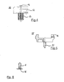
- a mounting clip 11 is shown made of plastic, which is provided with a recess 12 for receiving wire mesh by hanging. Via an integrally formed guide section 13, the mounting clip 11 can be inserted into the screw channel of the metal profile (not shown). The mounting clip 11 is then fastened thereto by means of a hook nail 14.
- FIG. 5 The in FIG. 5 mounting clip 11 ' is provided in connection with the use of grid mats as fence panels and has geometrically adapted thereto retaining formations 15. Also this mounting clip 11' is provided with a molded guide projection 13 'and is in the screw of the metal profile ultimately with the aid of a hammer in the Screwed in.
- the two-legged guide projection 13 ' prevents twisting of the holder and ensures a positive and non-positive fixation.
- the grid mat is fixed by a pressure clamp and a screw.
- FIG. 6 To FIG. 6 is in the region of the screw 6 of the fence post, not shown, a permanently elastic seal 16 introduced in the opening area.
- Plastic Montageklipps can serve as a mat holder or wire mesh fasteners and are pressed over the pin-like insertion in the screw.
- a separate toothing of the insertion section with a parallel rib structure of the screw channel correspond positively.
- the final fixation is ensured in all cases with additional screws or nails, so that the fence field attachment is reliably protected by external force by pressure or train, but also with respect to axial displacement. Due to the inventive fferkanaltechnik extraction forces of up to 6kN per screw can be achieved so that high safety requirements can be met.
- the screw head may be formed so that only special tools allow unscrewing to ensure a higher degree of security against sabotage. Additional decorative caps can cover the fasteners.
- the fence post assembly according to the invention provides a simple way of attaching different types of fence panels for the production of a fence, the screw in the fence post allows a continuous adjustment of the fence panels to the terrain.
Landscapes
- Engineering & Computer Science (AREA)
- Architecture (AREA)
- Civil Engineering (AREA)
- Structural Engineering (AREA)
- Fencing (AREA)
Applications Claiming Priority (1)
| Application Number | Priority Date | Filing Date | Title |
|---|---|---|---|
| DE102009053865A DE102009053865B4 (de) | 2009-11-20 | 2009-11-20 | Zaunpfostenanordnung mit einem kaltumgeformten Metallprofil |
Publications (2)
| Publication Number | Publication Date |
|---|---|
| EP2325418A2 true EP2325418A2 (fr) | 2011-05-25 |
| EP2325418A3 EP2325418A3 (fr) | 2013-05-22 |
Family
ID=43618790
Family Applications (1)
| Application Number | Title | Priority Date | Filing Date |
|---|---|---|---|
| EP10191808.4A Withdrawn EP2325418A3 (fr) | 2009-11-20 | 2010-11-19 | Agencement de piquets de clôture dotés d'un profilé métallique formé à froid |
Country Status (2)
| Country | Link |
|---|---|
| EP (1) | EP2325418A3 (fr) |
| DE (1) | DE102009053865B4 (fr) |
Families Citing this family (3)
| Publication number | Priority date | Publication date | Assignee | Title |
|---|---|---|---|---|
| DE102019100345A1 (de) * | 2019-01-08 | 2020-07-09 | Achim Stiehler Gmbh & Co. Kg | Pfosten für Zäune, wie beispielsweise Sichtschutzzäune |
| DE202020104375U1 (de) | 2020-07-29 | 2020-09-24 | Fritz Göbel GmbH & Co. KG | Zaunpfahl |
| AT17290U1 (de) * | 2020-08-18 | 2021-11-15 | H S Zauntechnik Ges M B H | Zaunsteher |
Citations (2)
| Publication number | Priority date | Publication date | Assignee | Title |
|---|---|---|---|---|
| DE2904907A1 (de) | 1979-02-09 | 1980-08-14 | Kraus Metallwaren Gmbh Konrad | Zaunpfahl und verfahren zu seiner herstellung |
| DE19753374A1 (de) | 1997-12-02 | 1999-06-17 | Froh Carl Gmbh | Vorrichtung zur Befestigung eines vertikale und horizontale Streben umfassenden Gitterfeldes an einem Zaunpfahl |
Family Cites Families (10)
| Publication number | Priority date | Publication date | Assignee | Title |
|---|---|---|---|---|
| US1360375A (en) * | 1920-05-15 | 1920-11-30 | Jurgen G Dammann | Fence-wire hanger and fencepost |
| DE1684770A1 (de) * | 1967-05-17 | 1970-03-19 | Kordes Kg Geb | Profiliertes Bauteil fuer Gartenzaeune,Zwischenwaende od. dgl. |
| FR2225035A5 (fr) * | 1973-04-04 | 1974-10-31 | Fornells Sa | |
| DE2738697A1 (de) * | 1977-08-27 | 1979-03-08 | Erhard Sahm | Schiene fuer die befestigung von balkon- und treppengelaendern, von zaeunen o.dgl. |
| DE8336194U1 (de) * | 1983-12-16 | 1984-09-06 | Bäsel, Lina, 6792 Ramstein-Miesenbach | Zahnpfosten aus rundrohr-walzprofil mit eingearbeitetem flansch und druchmesser von mindestens 80 mm, fuer ballfang, einschliesslich systemzubehoer |
| US4867421A (en) * | 1986-09-29 | 1989-09-19 | Vernon Kenneth O | Fence post |
| DE8807567U1 (de) * | 1988-06-01 | 1988-08-18 | Schönfeld, Hans Victor, 3180 Wolfsburg | Rohrprofil für Pfosten und Träger |
| US5110094A (en) * | 1990-09-07 | 1992-05-05 | Ppa Industries, Inc. | B-shaped structural member and fastening system |
| DE9404270U1 (de) * | 1994-03-14 | 1994-05-19 | Reitmaier Balkon Gmbh, 86476 Neuburg | Pfosten |
| DE19751167C1 (de) * | 1997-11-19 | 1999-06-24 | Bosch Gmbh Robert | Profilstab |
-
2009
- 2009-11-20 DE DE102009053865A patent/DE102009053865B4/de not_active Expired - Fee Related
-
2010
- 2010-11-19 EP EP10191808.4A patent/EP2325418A3/fr not_active Withdrawn
Patent Citations (2)
| Publication number | Priority date | Publication date | Assignee | Title |
|---|---|---|---|---|
| DE2904907A1 (de) | 1979-02-09 | 1980-08-14 | Kraus Metallwaren Gmbh Konrad | Zaunpfahl und verfahren zu seiner herstellung |
| DE19753374A1 (de) | 1997-12-02 | 1999-06-17 | Froh Carl Gmbh | Vorrichtung zur Befestigung eines vertikale und horizontale Streben umfassenden Gitterfeldes an einem Zaunpfahl |
Also Published As
| Publication number | Publication date |
|---|---|
| EP2325418A3 (fr) | 2013-05-22 |
| DE102009053865B4 (de) | 2013-04-04 |
| DE102009053865A1 (de) | 2011-05-26 |
Similar Documents
| Publication | Publication Date | Title |
|---|---|---|
| EP2096233A2 (fr) | Armature de support, revêtement de sol et procédé de fabrication d'un revêtement de sol | |
| EP2634347B1 (fr) | Support de verre, agencement de profilé et construction de cadre | |
| DE202007018765U1 (de) | Halterung für Verkleidungselemente bzw. eine Unterkonstruktion für Verkleidungselemente | |
| DE102009053865B4 (de) | Zaunpfostenanordnung mit einem kaltumgeformten Metallprofil | |
| DE102013021885A1 (de) | Vorrichtung zur Befestigung eines Fensters oder einer Tür in einer Wandöffnung und Verfahren zum Einbau eines Fensters oder einer Tür in eine Wandöffnung | |
| DE202013101629U1 (de) | Halteprofil für ein Rahmenprofil sowie rahmenintegrierte Absturzsicherung | |
| DE2451813A1 (de) | Zargenbefestigungseinrichtung | |
| DE202007009225U1 (de) | Überbrückungsdübel | |
| EP1321681B1 (fr) | Dispositif pour fixer une article à un objet et methode de fixation à un objet | |
| DE202016103578U1 (de) | Tragprofil, Montageflansch und Montagesystem | |
| DE2418205A1 (de) | Vorrichtung zum befestigen von fassadenverkleidungen o.dgl. | |
| EP2884004A2 (fr) | Poteau de support pour un mur ou une clôture et mur ou une clôture et combinaison de un mur et clôture | |
| EP2775083B1 (fr) | Assemblage de fixation, utilisation d'un dispositif et procédé de fixation d'un corps de bâtiment dans une ouverture limitée par une surface d'appui | |
| DE202013011471U1 (de) | Vorrichtung zur Befestigung eines Fensters oder einer Tür in einer Wandöffnung | |
| EP3342970A1 (fr) | Dispositif de garniture arrière ainsi que huisserie enveloppante associée | |
| EP3243993B1 (fr) | Dispositif et procédé de fixation d'un corps de bâtiment dans une ouverture limitée par une surface d'appui | |
| DE19828188C1 (de) | Fassadenprofil | |
| DE102009040131B3 (de) | Befestigungslasche für ein Schutzzaunfeld | |
| DE3401768C2 (de) | Mauerkanten-Schutzleistenanordnung | |
| DE102008015045B4 (de) | Vorrichtung zur Installation von elektrischen Leuchten an Decken von Gebäuden | |
| EP3798383A1 (fr) | Dispositif de retenue et procédé de fabrication d'une façade | |
| DE102007061781A1 (de) | Befestigungsvorrichtung für zwischen Pfosten anzuordnende Zaun- oder Sicherschutzelemente | |
| EP0058709A1 (fr) | Boulon d'ancrage | |
| DE6804257U (de) | Bauelementensatz zur befestigung von bespannungen an waenden und/oder decken | |
| DE29723466U1 (de) | Befestigungssystem für Innenraumeinrichtungen |
Legal Events
| Date | Code | Title | Description |
|---|---|---|---|
| PUAI | Public reference made under article 153(3) epc to a published international application that has entered the european phase |
Free format text: ORIGINAL CODE: 0009012 |
|
| AK | Designated contracting states |
Kind code of ref document: A2 Designated state(s): AL AT BE BG CH CY CZ DE DK EE ES FI FR GB GR HR HU IE IS IT LI LT LU LV MC MK MT NL NO PL PT RO RS SE SI SK SM TR |
|
| AX | Request for extension of the european patent |
Extension state: BA ME |
|
| PUAL | Search report despatched |
Free format text: ORIGINAL CODE: 0009013 |
|
| AK | Designated contracting states |
Kind code of ref document: A3 Designated state(s): AL AT BE BG CH CY CZ DE DK EE ES FI FR GB GR HR HU IE IS IT LI LT LU LV MC MK MT NL NO PL PT RO RS SE SI SK SM TR |
|
| AX | Request for extension of the european patent |
Extension state: BA ME |
|
| RIC1 | Information provided on ipc code assigned before grant |
Ipc: E04H 17/20 20060101AFI20130415BHEP Ipc: E04H 17/16 20060101ALI20130415BHEP |
|
| STAA | Information on the status of an ep patent application or granted ep patent |
Free format text: STATUS: THE APPLICATION IS DEEMED TO BE WITHDRAWN |
|
| 18D | Application deemed to be withdrawn |
Effective date: 20131123 |