EP2325427A2 - Motorisierte scharniervorrichtung für schwere drehtüre und drehtür mit einer solchen scharniervorrichtiung - Google Patents
Motorisierte scharniervorrichtung für schwere drehtüre und drehtür mit einer solchen scharniervorrichtiung Download PDFInfo
- Publication number
- EP2325427A2 EP2325427A2 EP10306235A EP10306235A EP2325427A2 EP 2325427 A2 EP2325427 A2 EP 2325427A2 EP 10306235 A EP10306235 A EP 10306235A EP 10306235 A EP10306235 A EP 10306235A EP 2325427 A2 EP2325427 A2 EP 2325427A2
- Authority
- EP
- European Patent Office
- Prior art keywords
- fixed
- hinge
- hinge portion
- rotation
- drive
- Prior art date
- Legal status (The legal status is an assumption and is not a legal conclusion. Google has not performed a legal analysis and makes no representation as to the accuracy of the status listed.)
- Granted
Links
Images


Classifications
-
- E—FIXED CONSTRUCTIONS
- E05—LOCKS; KEYS; WINDOW OR DOOR FITTINGS; SAFES
- E05F—DEVICES FOR MOVING WINGS INTO OPEN OR CLOSED POSITION; CHECKS FOR WINGS; WING FITTINGS NOT OTHERWISE PROVIDED FOR, CONCERNED WITH THE FUNCTIONING OF THE WING
- E05F15/00—Power-operated mechanisms for wings
- E05F15/60—Power-operated mechanisms for wings using electrical actuators
- E05F15/603—Power-operated mechanisms for wings using electrical actuators using rotary electromotors
- E05F15/611—Power-operated mechanisms for wings using electrical actuators using rotary electromotors for swinging wings
- E05F15/614—Power-operated mechanisms for wings using electrical actuators using rotary electromotors for swinging wings operated by meshing gear wheels, one of which being mounted at the wing pivot axis; operated by a motor acting directly on the wing pivot axis
-
- E—FIXED CONSTRUCTIONS
- E05—LOCKS; KEYS; WINDOW OR DOOR FITTINGS; SAFES
- E05D—HINGES OR SUSPENSION DEVICES FOR DOORS, WINDOWS OR WINGS
- E05D7/00—Hinges or pivots of special construction
- E05D7/06—Hinges or pivots of special construction to allow tilting of the members
-
- E—FIXED CONSTRUCTIONS
- E05—LOCKS; KEYS; WINDOW OR DOOR FITTINGS; SAFES
- E05Y—INDEXING SCHEME ASSOCIATED WITH SUBCLASSES E05D AND E05F, RELATING TO CONSTRUCTION ELEMENTS, ELECTRIC CONTROL, POWER SUPPLY, POWER SIGNAL OR TRANSMISSION, USER INTERFACES, MOUNTING OR COUPLING, DETAILS, ACCESSORIES, AUXILIARY OPERATIONS NOT OTHERWISE PROVIDED FOR, APPLICATION THEREOF
- E05Y2201/00—Constructional elements; Accessories therefor
- E05Y2201/40—Motors; Magnets; Springs; Weights; Accessories therefor
- E05Y2201/43—Motors
- E05Y2201/434—Electromotors; Details thereof
-
- E—FIXED CONSTRUCTIONS
- E05—LOCKS; KEYS; WINDOW OR DOOR FITTINGS; SAFES
- E05Y—INDEXING SCHEME ASSOCIATED WITH SUBCLASSES E05D AND E05F, RELATING TO CONSTRUCTION ELEMENTS, ELECTRIC CONTROL, POWER SUPPLY, POWER SIGNAL OR TRANSMISSION, USER INTERFACES, MOUNTING OR COUPLING, DETAILS, ACCESSORIES, AUXILIARY OPERATIONS NOT OTHERWISE PROVIDED FOR, APPLICATION THEREOF
- E05Y2201/00—Constructional elements; Accessories therefor
- E05Y2201/60—Suspension or transmission members; Accessories therefor
- E05Y2201/622—Suspension or transmission members elements
- E05Y2201/71—Toothed gearing
-
- E—FIXED CONSTRUCTIONS
- E05—LOCKS; KEYS; WINDOW OR DOOR FITTINGS; SAFES
- E05Y—INDEXING SCHEME ASSOCIATED WITH SUBCLASSES E05D AND E05F, RELATING TO CONSTRUCTION ELEMENTS, ELECTRIC CONTROL, POWER SUPPLY, POWER SIGNAL OR TRANSMISSION, USER INTERFACES, MOUNTING OR COUPLING, DETAILS, ACCESSORIES, AUXILIARY OPERATIONS NOT OTHERWISE PROVIDED FOR, APPLICATION THEREOF
- E05Y2600/00—Mounting or coupling arrangements for elements provided for in this subclass
- E05Y2600/10—Adjustable
-
- E—FIXED CONSTRUCTIONS
- E05—LOCKS; KEYS; WINDOW OR DOOR FITTINGS; SAFES
- E05Y—INDEXING SCHEME ASSOCIATED WITH SUBCLASSES E05D AND E05F, RELATING TO CONSTRUCTION ELEMENTS, ELECTRIC CONTROL, POWER SUPPLY, POWER SIGNAL OR TRANSMISSION, USER INTERFACES, MOUNTING OR COUPLING, DETAILS, ACCESSORIES, AUXILIARY OPERATIONS NOT OTHERWISE PROVIDED FOR, APPLICATION THEREOF
- E05Y2800/00—Details, accessories and auxiliary operations not otherwise provided for
- E05Y2800/20—Combinations of elements
- E05Y2800/23—Combinations of elements of elements of different categories
- E05Y2800/232—Combinations of elements of elements of different categories of motors and transmissions
-
- E—FIXED CONSTRUCTIONS
- E05—LOCKS; KEYS; WINDOW OR DOOR FITTINGS; SAFES
- E05Y—INDEXING SCHEME ASSOCIATED WITH SUBCLASSES E05D AND E05F, RELATING TO CONSTRUCTION ELEMENTS, ELECTRIC CONTROL, POWER SUPPLY, POWER SIGNAL OR TRANSMISSION, USER INTERFACES, MOUNTING OR COUPLING, DETAILS, ACCESSORIES, AUXILIARY OPERATIONS NOT OTHERWISE PROVIDED FOR, APPLICATION THEREOF
- E05Y2900/00—Application of doors, windows, wings or fittings thereof
- E05Y2900/10—Application of doors, windows, wings or fittings thereof for buildings or parts thereof
- E05Y2900/13—Type of wing
- E05Y2900/132—Doors
Definitions
- the present invention relates to the field of heavy hinged doors and comprising at least one leaf or leaf pivotally mounted on a frame through hinges and in particular hinged doors very heavy allowing more particularly access in hostile environments such as nuclear power plants , and relates to a motorized hinge device for such heavy hinged doors. It also relates to such a very heavy swing door equipped with said device.
- hinged doors weighing several tons
- Such hinges are generally constituted by a movable hinge portion secured to the hinge and by a fixed hinge portion secured to the frame, said hinge portion being rotatably mounted about the pivot axis corresponding to said hinge portion fixed.
- the movable hinge part usually forms a female part comprising a bearing intended to receive the axis of pivoting by sliding or by means of bearings, while said pivot axis is generally integral with the hinge part fixed or integrated in this last, pointing upwards.
- the current actuators are relatively expensive and occupy a large functional volume that makes their installation difficult or impossible on very heavy doors whose environment is very limited, which is particularly the case of doors very installed in the buildings of nuclear power plants.
- WO 2007/012965 relates to a motorized hinge system for door leaves or shutters, in particular of wood or aluminum, comprising a fixed wing with a hinged pivot, a movable wing, a geared motor fixed on a pivot axis, integral with the fixed wing, by its upper face by means of a plurality of screws, while the drive shaft of the geared motor fixed on said fixed wing crosses the latter extending into an axis integral with the mobile wing and coaxially traversing said pivot axis, to allow the rotational drive of the movable wing about said pivot axis.
- the present invention aims to overcome these disadvantages by proposing a motorized hinge device adaptable to a very heavy door and allowing installation and maintenance interventions or interchangeability easy and short-term, with a minimum of constraints, means actuating movement of the wing.
- the subject of the present invention is a motorized hinge device for a very heavy hinged door intended to be motorized and consisting of at least one flap or wing pivotally mounted about a substantially vertical axis of rotation on a frame , said device comprising a fixed hinge portion secured to said frame and a movable hinge portion secured to said leaf and rotatably mounted by relative to said fixed hinge portion about a pivot axis, said movable hinge portion having a drive mechanism driven by a motorization unit, preferably having a geared motor adapted to rotate said movable hinge portion around its pivot axis and thereby to move, by pivoting, opening or closing, said leaf, said motor block being removably mounted on said drive mechanism and on the fixed hinge portion and is characterized essentially in that said motor unit is fixed on the fixed hinge part by means of fast fixing and release means while being held in the driving position of said drive mechanism with anti-rotation blocking of said block relative to the leaf, possibly with a radial clearance.
- the present invention also relates to a very heavy motorized door and comprising at least one leaf or leaf pivotally mounted about a substantially vertical axis of rotation, on a frame through at least one lower hinge and d ' at least one upper hinge, said heavier door, characterized essentially in that at least one lower hinge consists of a motorized hinge device according to the present invention.
- the appended figures show a motorized hinge device for a very heavy hinged door intended to be motorized and constituted by at least one flap or leaf 1 pivotally mounted around a substantially vertical axis of rotation 1 ', on a frame 2, said device comprising a fixed hinge portion 3 secured to said frame 2 and a movable hinge portion 4 integral with said flap 1 and rotatably mounted relative to said fixed hinge portion 3 about a pivot axis 5, said movable hinge portion 4 having a drive mechanism 6, 8 moved by a motor unit 7, preferably comprising a geared motor 7 ', adapted to rotate said movable hinge portion 4 about its pivot axis 5 and thereby move by pivoting, in opening or closing, said leaf 1, said motor block 7 being removably mounted on said drive mechanism 6, 8 and on the p part of fixed hinge 3.
- the motor unit 7 is fixed on the fixed hinge portion 3 by means of fast fixing and release means 9, 10 being held in the driving position of said drive mechanism 6, 8 with locking anti-rotation of said block 7 relative to the wing 1, possibly with a radial clearance.
- the motor unit 7 can be mounted preferably on the upper face of the fixed hinge portion 3, resting more particularly thereon.
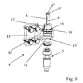
- the motor unit 7 may comprise a drive hub 12 and the drive mechanism may consist of a drive shaft 6 extending the mobile hinge part 4, coaxially with its pivot axis 5, said drive shaft. 6 training being moved in axial rotation by said drive hub 12 of the motor unit 7 by means of connecting and rotating means 8, 11 ( figure 4 and figure 9 ).
- connection and rotary drive means may consist of one or more keys 8 fixed on said drive shaft 6, for example being each fixed longitudinally on the outer face of said shaft 6 ( figure 9 ), and coming each engage in a keyway 11 ( figure 4 ) made in the drive hub 12 of the motor unit 6, so as to transmit the motor torque to the drive shaft 6 through said corresponding key 8.
- the advance 7 " may be profiled, preferably in the form of a generally rectangular parallelepiped, so as to have two opposite faces, respectively lower and upper, traversed substantially perpendicularly by said drive hub 12 which then opens on said faces opposite by two openings respectively lower 12 '( figure 7 ) and upper 12 “( figure 4 ), in order to allow, on the one hand, the introduction of the drive shaft 6 into said drive hub 12 preferably through the lower opening 12 ', hereinafter referred to as the feed opening 12 and, on the other hand, the holding with axial locking of the drive shaft 6 in said drive hub 12 by means of a stop 6 ', such as a washer, fixed, for example by means of a screw 6 ", and thus by nature removably, on the part of the free end of said drive shaft 6 protruding from the other opposite face, and bearing against the outer surface of said face ( figure 2 ) by preventing any withdrawal of said drive shaft 6 from said drive hub 12.
- a stop 6 ' such as a washer
- the motorization unit 7 can advantageously be removably fixed with anti-rotation locking on the fixed hinge portion 3 by means of a connecting piece 9 fixed to said motor unit 7 and comprising a connecting portion 13 providing the mechanical connection with said fixed hinge portion 3 via an axis or connecting finger and anti-rotation locking 10 fixed on the latter, the mechanical connection between the connecting portion 13 and said finger being, preferably, a mechanical connection with radial clearance capable of conferring a degree of freedom block 7 enabling possible small movements of the latter, when opening or closing the wing 1 ( figure 2 , figure 3 , Figure 7 and Figure 8 ).
- the connecting piece 9 receiving the connecting finger and anti-rotation locking 10 to allow the removable attachment of the motor unit 7, while preventing the rotation of said block relative to the wing 1, on a fixed part of the frame 2 and more particularly on the fixed hinge portion 3 and the drive shaft 6 extending the movable hinge part 4 for insertion into the hub 12 of the motor unit 7, allows easy interchangeability and short-term the latter that does not offer current systems that does not include such means for fast fixing and release of said block both on the movable hinge portion and on the fixed hinge portion.
- the connecting piece 9 can be advantageously fixed under the motorization block 7 and partly opposite the insertion opening 12 'of the drive shaft 6 in the drive hub 12 ( Figure 7 and Figure 8 ).
- connecting portion 13 constitutes a lateral extension of the portion of the connecting piece 9 located opposite said insertion opening 12 '.
- the present invention may provide that the anti-rotation connecting and locking finger 10 has an elongated shape, preferably substantially cylindrical, and is mechanically connected by one of its free ends to the connecting portion 13 of the connecting piece 9 and fixed by its other free end to the outer face of the fixed hinge portion 3, extending substantially parallel to the axis of rotation 1 'of the flap 1, distinctly from the movable hinge part 4.
- the fixed hinge portion 3 may have a profiled structure of generally cylindrical shape with a substantially vertical axis and the anti-rotation connecting and locking finger 10 may be fixed on the upper face of said fixed hinge portion 3 in extending substantially perpendicular to the latter, as can be seen in particular in the figure 2 and on the figure 3 .
- the connecting piece 9 can be made in the form of a plate fixed under the motorization block 7 and partly opposite the insertion opening 12 'of the drive shaft 6 in the hub of drive 12.
- Said connecting piece 9 in the form of a plate may advantageously extend in a plane substantially perpendicular to the axis 12 "'of the drive hub 12 and may comprise, on the one hand, a first light 9' fit to be traversed by said drive shaft 6 of the movable hinge portion 4 to allow the mechanical connection drive of said drive shaft 6 with said drive hub 12 and secondly a second 9 "light adapted to receive a portion of the corresponding free end of the connecting finger and anti-rotation lock 10 ( figure 4 ) in order to ensure the mechanical connection of said connecting piece 9 with said finger 10, in order to ensure an anti-rotation blocking of the motor unit 7, in particular around the axis 12 "'of the drive hub 12.
- the connecting piece 9 in the form of a plate is fixed under the motorization unit 7 by means of screws 9 IV , distributed preferably around the first opening 9 ', making it possible to clamp the said connecting piece 9 against the lower face 7 "'of said motor unit 7.
- the connecting piece 9, fixed on the motor unit 7 and mechanically connected to the connecting finger and anti-rotation blocking 10 secured to a fixed point of the very heavy door concerned and preferably the fixed hinge portion 3, is thus locked in rotation about the axis 12 "'of the drive hub 12, which has the effect of preventing any rotation of said motor unit 7, especially around said axis 12"'.
- a removable motor unit 7 used in the hinge device according to the present invention is maintained, with anti-rotation lock, in the rotational driving position of the mobile hinge part 4 and hence of the wing 1 of the very heavy door concerned, on the one hand, while being implanted functionally on the drive shaft 6 integral in rotation with the movable hinge portion 4 and, secondly, being locked in rotation about the axis 12 "'of the drive hub 12 via the connecting piece 9 receiving the connecting finger and anti-rotation locking 10 secured to the fixed hinge part 3.
- the present invention can advantageously provide that the second lumen 9 "has an oblong shape, of longitudinal axis 9"'passing substantially through the axis 12'"of the drive hub 12 of the motor unit 7, preferably of width substantially equal to the diameter of the portion of the corresponding free end of the generally cylindrical anti-rotation connecting and locking finger therethrough.said portion of the free end passing through said second oblong slot 9 is adapted to slide freely in the latter, so as to give it a radial clearance or degree of freedom of radial displacement in the direction of the length of said second oblong slot 9 "( figure 7 ) allowing to allow possible radial movements and small magnitude of said motor unit 7, when opening or closing the wing 1.
- the present invention can provide that the pivot axis 5 can be integral with the fixed hinge portion 3 and that the movable hinge portion 4 can be constituted by a support plate 14 intended to be fixed on the leaf 1, for example by means of screws 14 ', and extending by an arm 15 carrying at its free end a tip 16, preferably of generally cylindrical shape, having a receiving cavity or bearing 16' intended to receive the pivot axis 5 of the mobile hinge part 4 ( figure 2 , figure 3 and figure 9 ).
- the arm 15 may extend advantageously away from the plane of the wing 1, as can be seen for example on the figure 3 , so as to create a space or clearance sufficient to accommodate and implement the motorization unit 7, while the pivot axis 5 can advantageously be mounted on the fixed hinge part 3 ( figure 2 and figure 3 ).
- the drive shaft 6 of the movable hinge part 4 can be fixed on the upper face of the end piece 16 by means of a cover 17 of generally cylindrical shape having an enlarged base forming a crown of fixing 18 for its connection with rotational locking on said tip 16, preferably by screwing said 18 on said upper face of the latter and more particularly by screwing screws 19 regularly spaced over the entire circumference of said ring 18 ( figure 2 , figure 3 and figure 9 ).
- the subject of the present invention is also, as can be seen in particular on the figure 1 a very heavy motorized door having at least one leaf or leaf 1 pivotally mounted around a substantially vertical axis of rotation 1 ', on a frame 2 via a lower hinge 3, 4 and at least an upper hinge, not shown, of which at least one lower hinge 3, 4 consists of a motorized hinge device according to the present invention.
- the present invention may provide a preferred arrangement in which the motorization unit 7 may advantageously occupy a space contiguous to said frame 2, at the axis of rotation 1 'of the leaf 1, between the hinge (s) lower (s) 3, 4 and the upper hinge (s) of said door, that is to say substantially in the alignment of the hinge respectively lower and upper (s), this for the purpose of obtain a limited size of the engine block and an implementation at a location that requires no work in the frame or in the slab housing said door.
- Such an arrangement thus perfectly meets the constraints related to the restricted environment, even hostile, of such a door, including a door allowing access to an enclosed space in a nuclear power plant building.
- the rotational guidance of the movable hinge portion 4 relative to the fixed hinge portion 3 of each said lower hinge, about its pivot axis 5 can advantageously be achieved by interposition of radial rolling means intended to support mainly radial loads and axial rolling means intended to support mainly the axial loads, said rolling means being able to allow an angular defect of coaxiality of said portion of fixed hinge relative to said movable hinge portion, as described in French patent application no. 09 57975 on behalf of the plaintiff.
- each said upper hinge in accordance with the aforementioned French patent application, may advantageously comprise radial rolling means for to support mainly radial loads and being able to allow an angular defect of coaxiality of its fixed hinge portion relative to its movable hinge portion.
Landscapes
- Hinges (AREA)
- Power-Operated Mechanisms For Wings (AREA)
Applications Claiming Priority (1)
| Application Number | Priority Date | Filing Date | Title |
|---|---|---|---|
| FR0957977A FR2952396A1 (fr) | 2009-11-12 | 2009-11-12 | Dispositif de paumelle motorisee pour porte battante tres lourde et porte battante tres lourde equipee d'un tel dispositif |
Publications (3)
| Publication Number | Publication Date |
|---|---|
| EP2325427A2 true EP2325427A2 (de) | 2011-05-25 |
| EP2325427A3 EP2325427A3 (de) | 2012-07-18 |
| EP2325427B1 EP2325427B1 (de) | 2014-12-24 |
Family
ID=42269449
Family Applications (1)
| Application Number | Title | Priority Date | Filing Date |
|---|---|---|---|
| EP10306235.2A Active EP2325427B1 (de) | 2009-11-12 | 2010-11-10 | Motorisierte scharniervorrichtung für schwere drehtüre und drehtür mit einer solchen scharniervorrichtiung |
Country Status (4)
| Country | Link |
|---|---|
| US (1) | US8671620B2 (de) |
| EP (1) | EP2325427B1 (de) |
| CN (1) | CN102134944B (de) |
| FR (1) | FR2952396A1 (de) |
Families Citing this family (6)
| Publication number | Priority date | Publication date | Assignee | Title |
|---|---|---|---|---|
| CN103510816B (zh) * | 2013-10-11 | 2015-08-26 | 宜兴市万向防火门有限公司 | 一种核电门 |
| US11639625B2 (en) * | 2018-06-06 | 2023-05-02 | Richard Chi-Hsueh | Hinge system of electric door |
| CN115027234A (zh) * | 2022-06-07 | 2022-09-09 | 安徽安凯汽车股份有限公司 | 一种新型结构客车安全门总成 |
| CN117948024A (zh) * | 2022-10-31 | 2024-04-30 | 潍坊浩天消防设备有限公司 | 一种多功能智能入户门 |
| CN117027577B (zh) * | 2023-08-14 | 2026-04-07 | 温州东特科技有限公司 | 一种重型铰链 |
| WO2025117365A1 (en) * | 2023-11-27 | 2025-06-05 | Masonite Corporation | Powered hinge for door |
Citations (2)
| Publication number | Priority date | Publication date | Assignee | Title |
|---|---|---|---|---|
| FR957975A (de) | 1950-03-02 | |||
| WO2007012965A1 (en) | 2005-07-26 | 2007-02-01 | Mario Longoni | Universal motor hinge for door leaves and shutters |
Family Cites Families (14)
| Publication number | Priority date | Publication date | Assignee | Title |
|---|---|---|---|---|
| GB265388A (en) * | 1926-02-16 | 1927-02-10 | Chatwood Safe Company Ltd | Improvements relating to the doors of safes, strong rooms and the like |
| US5101595A (en) * | 1991-06-27 | 1992-04-07 | David Rhoades | Automatic gate opener with safety provisions |
| EP0910717A1 (de) | 1997-05-07 | 1999-04-28 | Anita Leppla | Elektrische antriebsvorrichtung für eine klappladen- oder klapptüranordnung oder dergleichen |
| IT1306377B1 (it) * | 1998-05-06 | 2001-06-06 | Mo De & Ti Pi Di Innocenti Giu | Dispositivo per movimentare e fermare, dall'interno dell'edificio, iserramenti esterni a battente. |
| US6032418A (en) * | 1998-11-09 | 2000-03-07 | Moog Inc. | Driven hinge with automatic driver-operated lock |
| ATE331112T1 (de) * | 1999-02-04 | 2006-07-15 | Stanley Works | Automatiktüranordnung und automatischer türbetätiger dafür |
| US6481160B1 (en) * | 1999-02-04 | 2002-11-19 | The Stanley Works | Axial door operator |
| US6422965B1 (en) * | 2000-04-20 | 2002-07-23 | Overhead Door Corporation | Door operator unit |
| US6731330B2 (en) * | 2001-01-30 | 2004-05-04 | Hewlett-Packard Development Company, L.P. | Method for robust determination of visible points of a controllable display within a camera view |
| US6751909B2 (en) * | 2001-02-06 | 2004-06-22 | The Stanley Works | Automatic door control system |
| US7367161B1 (en) * | 2004-04-30 | 2008-05-06 | Michael Wayne Jones | Gate opening and closing apparatus |
| DE202006010188U1 (de) * | 2005-12-28 | 2007-05-10 | Marantec Antriebs- Und Steuerungstechnik Gmbh & Co. Kg | Torantrieb |
| US8893435B2 (en) * | 2008-07-08 | 2014-11-25 | Chamberlain Australia Pty Ltd. | Method and apparatus for a movable barrier operator having a motor and a reduction mechanism disposed parallel to and laterally thereof |
| US8407937B2 (en) * | 2009-10-22 | 2013-04-02 | Yale Security Inc. | Door operator |
-
2009
- 2009-11-12 FR FR0957977A patent/FR2952396A1/fr not_active Withdrawn
-
2010
- 2010-11-10 EP EP10306235.2A patent/EP2325427B1/de active Active
- 2010-11-12 CN CN201010548642.7A patent/CN102134944B/zh not_active Expired - Fee Related
- 2010-11-12 US US12/945,238 patent/US8671620B2/en not_active Expired - Fee Related
Patent Citations (2)
| Publication number | Priority date | Publication date | Assignee | Title |
|---|---|---|---|---|
| FR957975A (de) | 1950-03-02 | |||
| WO2007012965A1 (en) | 2005-07-26 | 2007-02-01 | Mario Longoni | Universal motor hinge for door leaves and shutters |
Also Published As
| Publication number | Publication date |
|---|---|
| CN102134944A (zh) | 2011-07-27 |
| EP2325427B1 (de) | 2014-12-24 |
| US8671620B2 (en) | 2014-03-18 |
| FR2952396A1 (fr) | 2011-05-13 |
| EP2325427A3 (de) | 2012-07-18 |
| US20110107675A1 (en) | 2011-05-12 |
| CN102134944B (zh) | 2014-09-10 |
Similar Documents
| Publication | Publication Date | Title |
|---|---|---|
| EP2325427B1 (de) | Motorisierte scharniervorrichtung für schwere drehtüre und drehtür mit einer solchen scharniervorrichtiung | |
| CA2234436C (fr) | Dispositif de fermeture et de verrouillage des obturateurs d'un inverseur de poussee | |
| EP0179002B1 (de) | Einrichtung zum automatischen Schliessen, sowie zum Offenhalten von Türen | |
| FR2952397A1 (fr) | Dispositif de paumelle a montage oscillant destine a equiper une porte tres lourde et porte tres lourde equipee d'un tel dispositif | |
| EP3325753B1 (de) | Vorrichtung zum aufwickeln einer abschirmung mit einer scharnierwandbefestigung | |
| EP2799147B1 (de) | Laborzentrifuge, die mit Mitteln zum Verriegeln eines Deckels in geschlossener Position ausgestattet ist | |
| EP2248988A1 (de) | Aufhängung eines Torflügels für abschüssiges Gelände | |
| FR2905922A1 (fr) | Mecanisme de manoeuvre d'aiguilles | |
| EP1710381A1 (de) | Schwenkschiebetür für Eisenbahnwagen | |
| EP2360339B1 (de) | Stellglied mit Arm für Fenster- oder Türflügel | |
| EP2889444A1 (de) | Verlängerungssystem und -verfahren eines Lagerbolzens zum Montieren eines Öffnungsflügels auf einem existierenden Lagerbolzen, der im Mauerwerk fixiert ist | |
| EP1607568B1 (de) | Halter einer Wickelwelle und entsprechender Vorhang oder Sonnenschutz | |
| FR2815069A1 (fr) | Dispositif de deverrouillage de volets a battants entraines mecaniquement | |
| FR3027619A1 (fr) | Portail pivotant esthetique et fiabilise | |
| EP3530851B1 (de) | Verriegelungssystem für eine brandschutztür mit seitlicher verschiebung | |
| FR3096714A3 (fr) | Charnière de type à peigne pour fenêtre et portes à vantail pivotant | |
| EP4049959B1 (de) | Verfahren zur sicherung eines kippbaren auslegerkrans, um die winkelposition des kippbaren auslegers abzusichern | |
| EP1077303A1 (de) | Rolladensystem | |
| FR3111373A1 (fr) | Liaison motorisée de lames solaires | |
| BE1032138A1 (fr) | Grille de sécurité pliable | |
| FR2833640A1 (fr) | Dispositif de liaison de tetiere d'element de ferrure | |
| EP1953318A1 (de) | Ausgleichssystem einer Klappe | |
| FR2773193A1 (fr) | Dispositif d'ouverture-fermeture d'un battant de porte, de volet ou similaire | |
| EP1231355A1 (de) | Vorrichtung zur Immobilisierung einer Antriebsvorrichtung und Bedienungseinheit eines Verschlusses oder einer Sonnenschutzanlage mit einer solchen Anordnung | |
| FR2974838A1 (fr) | Sas tournant a montage et a fiabilite fonctionnelle ameliores |
Legal Events
| Date | Code | Title | Description |
|---|---|---|---|
| PUAI | Public reference made under article 153(3) epc to a published international application that has entered the european phase |
Free format text: ORIGINAL CODE: 0009012 |
|
| AK | Designated contracting states |
Kind code of ref document: A2 Designated state(s): AL AT BE BG CH CY CZ DE DK EE ES FI FR GB GR HR HU IE IS IT LI LT LU LV MC MK MT NL NO PL PT RO RS SE SI SK SM TR |
|
| AX | Request for extension of the european patent |
Extension state: BA ME |
|
| RTI1 | Title (correction) |
Free format text: MOTORIZED HINGE DEVICE FOR HEAVY PIVOTING DOORS AND HEAVY PIVOTING DOOR WITH SUCH A HINGE DEVICE |
|
| PUAL | Search report despatched |
Free format text: ORIGINAL CODE: 0009013 |
|
| AK | Designated contracting states |
Kind code of ref document: A3 Designated state(s): AL AT BE BG CH CY CZ DE DK EE ES FI FR GB GR HR HU IE IS IT LI LT LU LV MC MK MT NL NO PL PT RO RS SE SI SK SM TR |
|
| AX | Request for extension of the european patent |
Extension state: BA ME |
|
| RIC1 | Information provided on ipc code assigned before grant |
Ipc: E05F 15/12 20060101AFI20120612BHEP |
|
| 17P | Request for examination filed |
Effective date: 20130115 |
|
| GRAP | Despatch of communication of intention to grant a patent |
Free format text: ORIGINAL CODE: EPIDOSNIGR1 |
|
| INTG | Intention to grant announced |
Effective date: 20140616 |
|
| RIN1 | Information on inventor provided before grant (corrected) |
Inventor name: BOURGET, M. CHRISTIAN |
|
| GRAS | Grant fee paid |
Free format text: ORIGINAL CODE: EPIDOSNIGR3 |
|
| GRAA | (expected) grant |
Free format text: ORIGINAL CODE: 0009210 |
|
| AK | Designated contracting states |
Kind code of ref document: B1 Designated state(s): AL AT BE BG CH CY CZ DE DK EE ES FI FR GB GR HR HU IE IS IT LI LT LU LV MC MK MT NL NO PL PT RO RS SE SI SK SM TR |
|
| REG | Reference to a national code |
Ref country code: GB Ref legal event code: FG4D Free format text: NOT ENGLISH |
|
| REG | Reference to a national code |
Ref country code: CH Ref legal event code: EP |
|
| REG | Reference to a national code |
Ref country code: IE Ref legal event code: FG4D Free format text: LANGUAGE OF EP DOCUMENT: FRENCH |
|
| REG | Reference to a national code |
Ref country code: AT Ref legal event code: REF Ref document number: 703244 Country of ref document: AT Kind code of ref document: T Effective date: 20150115 |
|
| REG | Reference to a national code |
Ref country code: DE Ref legal event code: R096 Ref document number: 602010021235 Country of ref document: DE Effective date: 20150219 |
|
| REG | Reference to a national code |
Ref country code: NL Ref legal event code: VDEP Effective date: 20141224 |
|
| PG25 | Lapsed in a contracting state [announced via postgrant information from national office to epo] |
Ref country code: LT Free format text: LAPSE BECAUSE OF FAILURE TO SUBMIT A TRANSLATION OF THE DESCRIPTION OR TO PAY THE FEE WITHIN THE PRESCRIBED TIME-LIMIT Effective date: 20141224 Ref country code: NO Free format text: LAPSE BECAUSE OF FAILURE TO SUBMIT A TRANSLATION OF THE DESCRIPTION OR TO PAY THE FEE WITHIN THE PRESCRIBED TIME-LIMIT Effective date: 20150324 |
|
| REG | Reference to a national code |
Ref country code: LT Ref legal event code: MG4D |
|
| PG25 | Lapsed in a contracting state [announced via postgrant information from national office to epo] |
Ref country code: HR Free format text: LAPSE BECAUSE OF FAILURE TO SUBMIT A TRANSLATION OF THE DESCRIPTION OR TO PAY THE FEE WITHIN THE PRESCRIBED TIME-LIMIT Effective date: 20141224 Ref country code: LV Free format text: LAPSE BECAUSE OF FAILURE TO SUBMIT A TRANSLATION OF THE DESCRIPTION OR TO PAY THE FEE WITHIN THE PRESCRIBED TIME-LIMIT Effective date: 20141224 Ref country code: SE Free format text: LAPSE BECAUSE OF FAILURE TO SUBMIT A TRANSLATION OF THE DESCRIPTION OR TO PAY THE FEE WITHIN THE PRESCRIBED TIME-LIMIT Effective date: 20141224 Ref country code: GR Free format text: LAPSE BECAUSE OF FAILURE TO SUBMIT A TRANSLATION OF THE DESCRIPTION OR TO PAY THE FEE WITHIN THE PRESCRIBED TIME-LIMIT Effective date: 20150325 Ref country code: RS Free format text: LAPSE BECAUSE OF FAILURE TO SUBMIT A TRANSLATION OF THE DESCRIPTION OR TO PAY THE FEE WITHIN THE PRESCRIBED TIME-LIMIT Effective date: 20141224 |
|
| REG | Reference to a national code |
Ref country code: AT Ref legal event code: MK05 Ref document number: 703244 Country of ref document: AT Kind code of ref document: T Effective date: 20141224 |
|
| PG25 | Lapsed in a contracting state [announced via postgrant information from national office to epo] |
Ref country code: NL Free format text: LAPSE BECAUSE OF FAILURE TO SUBMIT A TRANSLATION OF THE DESCRIPTION OR TO PAY THE FEE WITHIN THE PRESCRIBED TIME-LIMIT Effective date: 20141224 |
|
| PG25 | Lapsed in a contracting state [announced via postgrant information from national office to epo] |
Ref country code: CZ Free format text: LAPSE BECAUSE OF FAILURE TO SUBMIT A TRANSLATION OF THE DESCRIPTION OR TO PAY THE FEE WITHIN THE PRESCRIBED TIME-LIMIT Effective date: 20141224 Ref country code: EE Free format text: LAPSE BECAUSE OF FAILURE TO SUBMIT A TRANSLATION OF THE DESCRIPTION OR TO PAY THE FEE WITHIN THE PRESCRIBED TIME-LIMIT Effective date: 20141224 Ref country code: ES Free format text: LAPSE BECAUSE OF FAILURE TO SUBMIT A TRANSLATION OF THE DESCRIPTION OR TO PAY THE FEE WITHIN THE PRESCRIBED TIME-LIMIT Effective date: 20141224 Ref country code: SK Free format text: LAPSE BECAUSE OF FAILURE TO SUBMIT A TRANSLATION OF THE DESCRIPTION OR TO PAY THE FEE WITHIN THE PRESCRIBED TIME-LIMIT Effective date: 20141224 Ref country code: RO Free format text: LAPSE BECAUSE OF FAILURE TO SUBMIT A TRANSLATION OF THE DESCRIPTION OR TO PAY THE FEE WITHIN THE PRESCRIBED TIME-LIMIT Effective date: 20141224 |
|
| PG25 | Lapsed in a contracting state [announced via postgrant information from national office to epo] |
Ref country code: AT Free format text: LAPSE BECAUSE OF FAILURE TO SUBMIT A TRANSLATION OF THE DESCRIPTION OR TO PAY THE FEE WITHIN THE PRESCRIBED TIME-LIMIT Effective date: 20141224 Ref country code: IS Free format text: LAPSE BECAUSE OF FAILURE TO SUBMIT A TRANSLATION OF THE DESCRIPTION OR TO PAY THE FEE WITHIN THE PRESCRIBED TIME-LIMIT Effective date: 20150424 Ref country code: PL Free format text: LAPSE BECAUSE OF FAILURE TO SUBMIT A TRANSLATION OF THE DESCRIPTION OR TO PAY THE FEE WITHIN THE PRESCRIBED TIME-LIMIT Effective date: 20141224 |
|
| REG | Reference to a national code |
Ref country code: DE Ref legal event code: R097 Ref document number: 602010021235 Country of ref document: DE |
|
| PG25 | Lapsed in a contracting state [announced via postgrant information from national office to epo] |
Ref country code: DK Free format text: LAPSE BECAUSE OF FAILURE TO SUBMIT A TRANSLATION OF THE DESCRIPTION OR TO PAY THE FEE WITHIN THE PRESCRIBED TIME-LIMIT Effective date: 20141224 |
|
| PLBE | No opposition filed within time limit |
Free format text: ORIGINAL CODE: 0009261 |
|
| STAA | Information on the status of an ep patent application or granted ep patent |
Free format text: STATUS: NO OPPOSITION FILED WITHIN TIME LIMIT |
|
| REG | Reference to a national code |
Ref country code: FR Ref legal event code: PLFP Year of fee payment: 6 |
|
| 26N | No opposition filed |
Effective date: 20150925 |
|
| PG25 | Lapsed in a contracting state [announced via postgrant information from national office to epo] |
Ref country code: IT Free format text: LAPSE BECAUSE OF FAILURE TO SUBMIT A TRANSLATION OF THE DESCRIPTION OR TO PAY THE FEE WITHIN THE PRESCRIBED TIME-LIMIT Effective date: 20141224 |
|
| PG25 | Lapsed in a contracting state [announced via postgrant information from national office to epo] |
Ref country code: SI Free format text: LAPSE BECAUSE OF FAILURE TO SUBMIT A TRANSLATION OF THE DESCRIPTION OR TO PAY THE FEE WITHIN THE PRESCRIBED TIME-LIMIT Effective date: 20141224 |
|
| REG | Reference to a national code |
Ref country code: DE Ref legal event code: R082 Ref document number: 602010021235 Country of ref document: DE Representative=s name: CABINET NUSS, FR |
|
| PG25 | Lapsed in a contracting state [announced via postgrant information from national office to epo] |
Ref country code: LU Free format text: LAPSE BECAUSE OF FAILURE TO SUBMIT A TRANSLATION OF THE DESCRIPTION OR TO PAY THE FEE WITHIN THE PRESCRIBED TIME-LIMIT Effective date: 20151110 Ref country code: MC Free format text: LAPSE BECAUSE OF FAILURE TO SUBMIT A TRANSLATION OF THE DESCRIPTION OR TO PAY THE FEE WITHIN THE PRESCRIBED TIME-LIMIT Effective date: 20141224 |
|
| REG | Reference to a national code |
Ref country code: CH Ref legal event code: PL |
|
| PG25 | Lapsed in a contracting state [announced via postgrant information from national office to epo] |
Ref country code: LI Free format text: LAPSE BECAUSE OF NON-PAYMENT OF DUE FEES Effective date: 20151130 Ref country code: CH Free format text: LAPSE BECAUSE OF NON-PAYMENT OF DUE FEES Effective date: 20151130 |
|
| REG | Reference to a national code |
Ref country code: IE Ref legal event code: MM4A |
|
| PG25 | Lapsed in a contracting state [announced via postgrant information from national office to epo] |
Ref country code: IE Free format text: LAPSE BECAUSE OF NON-PAYMENT OF DUE FEES Effective date: 20151110 |
|
| REG | Reference to a national code |
Ref country code: FR Ref legal event code: PLFP Year of fee payment: 7 |
|
| PGFP | Annual fee paid to national office [announced via postgrant information from national office to epo] |
Ref country code: DE Payment date: 20161116 Year of fee payment: 7 |
|
| PG25 | Lapsed in a contracting state [announced via postgrant information from national office to epo] |
Ref country code: SM Free format text: LAPSE BECAUSE OF FAILURE TO SUBMIT A TRANSLATION OF THE DESCRIPTION OR TO PAY THE FEE WITHIN THE PRESCRIBED TIME-LIMIT Effective date: 20141224 Ref country code: BG Free format text: LAPSE BECAUSE OF FAILURE TO SUBMIT A TRANSLATION OF THE DESCRIPTION OR TO PAY THE FEE WITHIN THE PRESCRIBED TIME-LIMIT Effective date: 20141224 Ref country code: HU Free format text: LAPSE BECAUSE OF FAILURE TO SUBMIT A TRANSLATION OF THE DESCRIPTION OR TO PAY THE FEE WITHIN THE PRESCRIBED TIME-LIMIT; INVALID AB INITIO Effective date: 20101110 |
|
| PG25 | Lapsed in a contracting state [announced via postgrant information from national office to epo] |
Ref country code: CY Free format text: LAPSE BECAUSE OF FAILURE TO SUBMIT A TRANSLATION OF THE DESCRIPTION OR TO PAY THE FEE WITHIN THE PRESCRIBED TIME-LIMIT Effective date: 20141224 |
|
| PG25 | Lapsed in a contracting state [announced via postgrant information from national office to epo] |
Ref country code: BE Free format text: LAPSE BECAUSE OF NON-PAYMENT OF DUE FEES Effective date: 20151130 |
|
| PG25 | Lapsed in a contracting state [announced via postgrant information from national office to epo] |
Ref country code: TR Free format text: LAPSE BECAUSE OF FAILURE TO SUBMIT A TRANSLATION OF THE DESCRIPTION OR TO PAY THE FEE WITHIN THE PRESCRIBED TIME-LIMIT Effective date: 20141224 Ref country code: MT Free format text: LAPSE BECAUSE OF FAILURE TO SUBMIT A TRANSLATION OF THE DESCRIPTION OR TO PAY THE FEE WITHIN THE PRESCRIBED TIME-LIMIT Effective date: 20141224 |
|
| REG | Reference to a national code |
Ref country code: FR Ref legal event code: PLFP Year of fee payment: 8 |
|
| REG | Reference to a national code |
Ref country code: DE Ref legal event code: R119 Ref document number: 602010021235 Country of ref document: DE |
|
| PG25 | Lapsed in a contracting state [announced via postgrant information from national office to epo] |
Ref country code: MK Free format text: LAPSE BECAUSE OF FAILURE TO SUBMIT A TRANSLATION OF THE DESCRIPTION OR TO PAY THE FEE WITHIN THE PRESCRIBED TIME-LIMIT Effective date: 20141224 |
|
| PG25 | Lapsed in a contracting state [announced via postgrant information from national office to epo] |
Ref country code: PT Free format text: LAPSE BECAUSE OF FAILURE TO SUBMIT A TRANSLATION OF THE DESCRIPTION OR TO PAY THE FEE WITHIN THE PRESCRIBED TIME-LIMIT Effective date: 20141224 |
|
| PG25 | Lapsed in a contracting state [announced via postgrant information from national office to epo] |
Ref country code: DE Free format text: LAPSE BECAUSE OF NON-PAYMENT OF DUE FEES Effective date: 20180602 Ref country code: AL Free format text: LAPSE BECAUSE OF FAILURE TO SUBMIT A TRANSLATION OF THE DESCRIPTION OR TO PAY THE FEE WITHIN THE PRESCRIBED TIME-LIMIT Effective date: 20141224 |
|
| PGFP | Annual fee paid to national office [announced via postgrant information from national office to epo] |
Ref country code: FI Payment date: 20181120 Year of fee payment: 9 |
|
| REG | Reference to a national code |
Ref country code: FI Ref legal event code: MAE |
|
| PG25 | Lapsed in a contracting state [announced via postgrant information from national office to epo] |
Ref country code: FI Free format text: LAPSE BECAUSE OF NON-PAYMENT OF DUE FEES Effective date: 20191110 |
|
| P01 | Opt-out of the competence of the unified patent court (upc) registered |
Effective date: 20230621 |
|
| PGFP | Annual fee paid to national office [announced via postgrant information from national office to epo] |
Ref country code: GB Payment date: 20251128 Year of fee payment: 16 |
|
| PGFP | Annual fee paid to national office [announced via postgrant information from national office to epo] |
Ref country code: FR Payment date: 20251128 Year of fee payment: 16 |