EP2325452A1 - Vorrichtung zur Nachbehandlung von Abgasen von Brennkraftmaschinen - Google Patents
Vorrichtung zur Nachbehandlung von Abgasen von Brennkraftmaschinen Download PDFInfo
- Publication number
- EP2325452A1 EP2325452A1 EP10010243A EP10010243A EP2325452A1 EP 2325452 A1 EP2325452 A1 EP 2325452A1 EP 10010243 A EP10010243 A EP 10010243A EP 10010243 A EP10010243 A EP 10010243A EP 2325452 A1 EP2325452 A1 EP 2325452A1
- Authority
- EP
- European Patent Office
- Prior art keywords
- inlet
- reducing agent
- exhaust gas
- flow
- exhaust
- Prior art date
- Legal status (The legal status is an assumption and is not a legal conclusion. Google has not performed a legal analysis and makes no representation as to the accuracy of the status listed.)
- Granted
Links
Images



Classifications
-
- F—MECHANICAL ENGINEERING; LIGHTING; HEATING; WEAPONS; BLASTING
- F01—MACHINES OR ENGINES IN GENERAL; ENGINE PLANTS IN GENERAL; STEAM ENGINES
- F01N—GAS-FLOW SILENCERS OR EXHAUST APPARATUS FOR MACHINES OR ENGINES IN GENERAL; GAS-FLOW SILENCERS OR EXHAUST APPARATUS FOR INTERNAL-COMBUSTION ENGINES
- F01N3/00—Exhaust or silencing apparatus having means for purifying, rendering innocuous, or otherwise treating exhaust
- F01N3/08—Exhaust or silencing apparatus having means for purifying, rendering innocuous, or otherwise treating exhaust for rendering innocuous
- F01N3/10—Exhaust or silencing apparatus having means for purifying, rendering innocuous, or otherwise treating exhaust for rendering innocuous by thermal or catalytic conversion of noxious components of exhaust
- F01N3/24—Exhaust or silencing apparatus having means for purifying, rendering innocuous, or otherwise treating exhaust for rendering innocuous by thermal or catalytic conversion of noxious components of exhaust characterised by constructional aspects of converting apparatus
- F01N3/28—Construction of catalytic reactors
- F01N3/2892—Exhaust flow directors or the like, e.g. upstream of catalytic device
-
- F—MECHANICAL ENGINEERING; LIGHTING; HEATING; WEAPONS; BLASTING
- F01—MACHINES OR ENGINES IN GENERAL; ENGINE PLANTS IN GENERAL; STEAM ENGINES
- F01N—GAS-FLOW SILENCERS OR EXHAUST APPARATUS FOR MACHINES OR ENGINES IN GENERAL; GAS-FLOW SILENCERS OR EXHAUST APPARATUS FOR INTERNAL-COMBUSTION ENGINES
- F01N3/00—Exhaust or silencing apparatus having means for purifying, rendering innocuous, or otherwise treating exhaust
- F01N3/08—Exhaust or silencing apparatus having means for purifying, rendering innocuous, or otherwise treating exhaust for rendering innocuous
- F01N3/10—Exhaust or silencing apparatus having means for purifying, rendering innocuous, or otherwise treating exhaust for rendering innocuous by thermal or catalytic conversion of noxious components of exhaust
- F01N3/18—Exhaust or silencing apparatus having means for purifying, rendering innocuous, or otherwise treating exhaust for rendering innocuous by thermal or catalytic conversion of noxious components of exhaust characterised by methods of operation; Control
- F01N3/20—Exhaust or silencing apparatus having means for purifying, rendering innocuous, or otherwise treating exhaust for rendering innocuous by thermal or catalytic conversion of noxious components of exhaust characterised by methods of operation; Control specially adapted for catalytic conversion
- F01N3/206—Adding periodically or continuously substances to exhaust gases for promoting purification, e.g. catalytic material in liquid form, NOx reducing agents
- F01N3/2066—Selective catalytic reduction [SCR]
-
- F—MECHANICAL ENGINEERING; LIGHTING; HEATING; WEAPONS; BLASTING
- F01—MACHINES OR ENGINES IN GENERAL; ENGINE PLANTS IN GENERAL; STEAM ENGINES
- F01N—GAS-FLOW SILENCERS OR EXHAUST APPARATUS FOR MACHINES OR ENGINES IN GENERAL; GAS-FLOW SILENCERS OR EXHAUST APPARATUS FOR INTERNAL-COMBUSTION ENGINES
- F01N2240/00—Combination or association of two or more different exhaust treating devices, or of at least one such device with an auxiliary device, not covered by indexing codes F01N2230/00 or F01N2250/00, one of the devices being
- F01N2240/20—Combination or association of two or more different exhaust treating devices, or of at least one such device with an auxiliary device, not covered by indexing codes F01N2230/00 or F01N2250/00, one of the devices being a flow director or deflector
-
- F—MECHANICAL ENGINEERING; LIGHTING; HEATING; WEAPONS; BLASTING
- F01—MACHINES OR ENGINES IN GENERAL; ENGINE PLANTS IN GENERAL; STEAM ENGINES
- F01N—GAS-FLOW SILENCERS OR EXHAUST APPARATUS FOR MACHINES OR ENGINES IN GENERAL; GAS-FLOW SILENCERS OR EXHAUST APPARATUS FOR INTERNAL-COMBUSTION ENGINES
- F01N2240/00—Combination or association of two or more different exhaust treating devices, or of at least one such device with an auxiliary device, not covered by indexing codes F01N2230/00 or F01N2250/00, one of the devices being
- F01N2240/40—Combination or association of two or more different exhaust treating devices, or of at least one such device with an auxiliary device, not covered by indexing codes F01N2230/00 or F01N2250/00, one of the devices being a hydrolysis catalyst
-
- F—MECHANICAL ENGINEERING; LIGHTING; HEATING; WEAPONS; BLASTING
- F01—MACHINES OR ENGINES IN GENERAL; ENGINE PLANTS IN GENERAL; STEAM ENGINES
- F01N—GAS-FLOW SILENCERS OR EXHAUST APPARATUS FOR MACHINES OR ENGINES IN GENERAL; GAS-FLOW SILENCERS OR EXHAUST APPARATUS FOR INTERNAL-COMBUSTION ENGINES
- F01N2470/00—Structure or shape of exhaust gas passages, pipes or tubes
- F01N2470/18—Structure or shape of exhaust gas passages, pipes or tubes the axis of inlet or outlet tubes being other than the longitudinal axis of apparatus
-
- F—MECHANICAL ENGINEERING; LIGHTING; HEATING; WEAPONS; BLASTING
- F01—MACHINES OR ENGINES IN GENERAL; ENGINE PLANTS IN GENERAL; STEAM ENGINES
- F01N—GAS-FLOW SILENCERS OR EXHAUST APPARATUS FOR MACHINES OR ENGINES IN GENERAL; GAS-FLOW SILENCERS OR EXHAUST APPARATUS FOR INTERNAL-COMBUSTION ENGINES
- F01N2490/00—Structure, disposition or shape of gas-chambers
- F01N2490/02—Two or more expansion chambers in series connected by means of tubes
- F01N2490/06—Two or more expansion chambers in series connected by means of tubes the gases flowing longitudinally from inlet to outlet in opposite directions
-
- F—MECHANICAL ENGINEERING; LIGHTING; HEATING; WEAPONS; BLASTING
- F01—MACHINES OR ENGINES IN GENERAL; ENGINE PLANTS IN GENERAL; STEAM ENGINES
- F01N—GAS-FLOW SILENCERS OR EXHAUST APPARATUS FOR MACHINES OR ENGINES IN GENERAL; GAS-FLOW SILENCERS OR EXHAUST APPARATUS FOR INTERNAL-COMBUSTION ENGINES
- F01N2610/00—Adding substances to exhaust gases
- F01N2610/02—Adding substances to exhaust gases the substance being ammonia or urea
-
- F—MECHANICAL ENGINEERING; LIGHTING; HEATING; WEAPONS; BLASTING
- F01—MACHINES OR ENGINES IN GENERAL; ENGINE PLANTS IN GENERAL; STEAM ENGINES
- F01N—GAS-FLOW SILENCERS OR EXHAUST APPARATUS FOR MACHINES OR ENGINES IN GENERAL; GAS-FLOW SILENCERS OR EXHAUST APPARATUS FOR INTERNAL-COMBUSTION ENGINES
- F01N2610/00—Adding substances to exhaust gases
- F01N2610/14—Arrangements for the supply of substances, e.g. conduits
- F01N2610/1453—Sprayers or atomisers; Arrangement thereof in the exhaust apparatus
-
- Y—GENERAL TAGGING OF NEW TECHNOLOGICAL DEVELOPMENTS; GENERAL TAGGING OF CROSS-SECTIONAL TECHNOLOGIES SPANNING OVER SEVERAL SECTIONS OF THE IPC; TECHNICAL SUBJECTS COVERED BY FORMER USPC CROSS-REFERENCE ART COLLECTIONS [XRACs] AND DIGESTS
- Y02—TECHNOLOGIES OR APPLICATIONS FOR MITIGATION OR ADAPTATION AGAINST CLIMATE CHANGE
- Y02A—TECHNOLOGIES FOR ADAPTATION TO CLIMATE CHANGE
- Y02A50/00—TECHNOLOGIES FOR ADAPTATION TO CLIMATE CHANGE in human health protection, e.g. against extreme weather
- Y02A50/20—Air quality improvement or preservation, e.g. vehicle emission control or emission reduction by using catalytic converters
-
- Y—GENERAL TAGGING OF NEW TECHNOLOGICAL DEVELOPMENTS; GENERAL TAGGING OF CROSS-SECTIONAL TECHNOLOGIES SPANNING OVER SEVERAL SECTIONS OF THE IPC; TECHNICAL SUBJECTS COVERED BY FORMER USPC CROSS-REFERENCE ART COLLECTIONS [XRACs] AND DIGESTS
- Y02—TECHNOLOGIES OR APPLICATIONS FOR MITIGATION OR ADAPTATION AGAINST CLIMATE CHANGE
- Y02T—CLIMATE CHANGE MITIGATION TECHNOLOGIES RELATED TO TRANSPORTATION
- Y02T10/00—Road transport of goods or passengers
- Y02T10/10—Internal combustion engine [ICE] based vehicles
- Y02T10/12—Improving ICE efficiencies
Definitions
- the invention relates to a device for the after-treatment of exhaust gases of internal combustion engines, in particular of lean-running internal combustion engines of motor vehicles, according to the preamble of claim 1.
- SCR catalysts for reducing the nitrogen oxides in an exhaust gas stream of an internal combustion engine are well known.
- SCR selective catalytic reduction
- the exhaust gas stream is supplied with an immediately reducing substance, such as, for example, ammonia or a precursor, which liberates substances which reduce the exhaust gas only.
- an immediately reducing substance such as, for example, ammonia or a precursor, which liberates substances which reduce the exhaust gas only.
- a precursor for example, an aqueous urea solution can be used.
- nitrogen oxide reduction with the aid of the SCR method is therefore difficult because there are changing operating conditions prevailing, which makes the quantitative metering of the reducing agent more difficult.
- the highest possible conversion of nitrogen oxides is to be achieved, on the other hand it is also make sure that there is no unnecessary emission of unused reducing agent, such as ammonia.
- thermolysis that is, the thermal decomposition of urea.
- hydrolysis ie the catalytic decomposition of isocyanic acid (HNCO) into ammonia (NH 3 ) and carbon dioxide (CO 2 ).
- the reducing agent in the case of, for example, the use of the reducing liquid designated as AdBlue® is in a form dissolved in water, this water must evaporate before and during the actual thermolysis and hydrolysis. If the temperatures in the two above reactions below 350 ° C or is heated slowly, forms mainly solid infusible cyanuric acid by trimerization of isocyanic acid, resulting in solid deposits or even clogging of the SCR catalyst. Remedy can be here, as in the DE 40 38 054 A1 described, be created by the exhaust gas flow laden with the reducing agent is passed over a hydrolysis catalyst. The exhaust gas temperature, at which a quantitative hydrolysis is possible, can be lowered to 160 ° C.
- the hydrolysis catalysts can also be operated in a partial exhaust stream, which is taken from the exhaust gas stream and fed back to it after hydrolysis.
- a corresponding arrangement is the EP 1052009 A1 refer to.
- this method does not completely solve the problem of only partial urea hydrolysis if the exhaust gas temperatures are too low.
- the object of the invention is to propose a device for the aftertreatment of exhaust gases in an exhaust system of internal combustion engines, especially of lean-running internal combustion engines of motor vehicles, such as commercial vehicles, which enables a functional, in particular quantitatively improved decomposition of the reducing agent in the exhaust gas in a simple and functionally reliable manner and which requires only a small amount of space.
- a device for the aftertreatment of exhaust gases in an exhaust system of internal combustion engines, in particular of lean-running internal combustion engines for motor vehicles, with at least one switched into the exhaust stream reducing agent decomposition catalyst, in particular a hydrolysis catalyst is provided. Furthermore, upstream of it is in an exhaust pipe arranged a metering device for supplying reducing agent, in particular for supplying an aqueous urea solution. Furthermore, a catalyst device arranged downstream of the reducing agent decomposition catalyst, which is formed in particular by at least one SCR catalyst, is preferably provided.
- the reducing agent decomposition catalyst is preceded by an inlet section for the exhaust gas which has at least one flow deflection region and which is configured such that the exhaust gas is fed radially outside a housing tube surrounding the inlet tube into a housing section surrounding the inlet tube and is passed countercurrently via an end inlet opening of the inlet tube to the reductant decomposition catalyst is, wherein the reducing agent is supplied in the, associated with the inlet opening Strömungsumsch Scheme the exhaust gas stream.
- the uniform distribution of flow through throttling or throttling can be improved.
- at least one upstream of the supply of the reducing agent in the region of the inlet path Throttle device be provided for throttling or throttling the exhaust stream and / or the flow cross-section upstream of the supply of the reducing agent may be formed smaller than downstream of the supply of the reducing agent.
- the exhaust aftertreatment system according to the invention thus advantageously makes it possible to quantitatively decompose the reducing agent without impairing the efficiency of the internal combustion engine.
- the volume flowed through in the inlet section outside the inlet tube is smaller than the volume flowed through within the inlet tube.
- the flow can additionally be influenced by internals which are located in the front region of the inlet pipe but downstream of the metering point for the reducing agent. These may be, for example, sheets that protrude into the flow and thereby increase the turbulence. However, it must be ensured that no reducing agent meets these internals in order to To avoid deposits on these.
- the inlet opening is bounded by a circulating edge which generates flow turbulence and which can be formed, for example, by a circumferential edge having battlements.
- the number and geometry of the pinnacles is here then as well as the distance to vote on the particular case to choose.
- the inlet tube can basically have any cross-sectional shape, that is to say be cylindrical or angular, for example.
- the inlet tube is particularly preferably formed by a funnel-shaped or cone-shaped inlet funnel, which tapers towards the inlet opening, so that the inlet opening simultaneously forms a throttle cross-section.
- the inner walls of the inlet tube can advantageously be catalytically active coated.
- the coating may preferably consist of TiO 2 , SiO 2 or AlO 2 or be formed by zeolites and contributes to a further improved decomposition of the reducing agent in NH 3 (ammonia) and to avoid deposits on the relevant exhaust-carrying parts.
- an evaporator and / or mixer is mounted downstream of the feed for the reducing agent.
- an evaporator and / or mixer is arranged in the inlet pipe, which has a defined distance from the inlet opening, preferably in about 2/3 of the pipe length of the inlet pipe, seen from the inlet opening, is inserted.
- Such an optional evaporator and / or mixer allows an even more intensive uniform distribution of the metered reducing agent in the region of the inlet pipe.
- a nozzle of the metering device for supplying the reducing agent be arranged in the flow deflection region of the exhaust gas flow assigned to the inlet opening and / or directed towards the inlet opening. This ensures in a simple way that the Reducing agent can reliably and completely enter the inlet pipe and thus the reducing agent decomposition catalyst.
- the nozzle is arranged on an end wall of the housing section surrounding the inlet pipe, the inlet opening of the inlet pipe at a defined distance opposite.
- the nozzle can be arranged with respect to its injection direction into the inlet opening of the inlet pipe coaxially to the longitudinal central axis of the inlet pipe, whereby a functionally reliable central metering into the inlet pipe is made possible.
- the nozzle can also be arranged eccentrically offset to the longitudinal central axis of the inlet pipe, whereby a simple vote of the local reducing agent quantity on the local flow rates succeed, which contributes to a good mixing of reducing agent and exhaust gas flow
- one or more, in particular a plurality of circumferentially distributed bypass openings may be formed on the inlet pipe, by means of which the inlet section or the flow deflection region can preferably be bypassed and / or by means of which the exhaust gas back pressure upstream of the inlet section can be reduced to the desired extent.
- the at least one bypass opening can also be blown off in order to reduce the flow velocity in the reducing agent supply region, that is, for example, in the nozzle region.
- the bypass openings cause a better uniform distribution in the immediate vicinity of the inlet surface of the reducing agent decomposition catalyst and a direct, temperature-increasing flow of the same.
- At least one further throttle point for the inflowing exhaust gas can furthermore be provided in the housing section surrounding the inlet pipe upstream of the flow deflection region assigned to the inlet opening of the inlet pipe and thus upstream of the reducing agent feed and outside the inlet pipe.
- the flow rate can locally and selectively influence such that in the deflection or in the nozzle of the metering targeted flow conditions and turbulence in the thermal inlet section abut or can be adjusted.
- the restriction is e.g.
- the flow velocity in the area of the reducing agent feed may alternatively or additionally be provided for blowing over the at least one bypass opening to arrange the throttle point at a defined distance from the inlet opening of the inlet tube.
- the throttle point is e.g. arranged approximately halfway between the at least one bypass opening and the inlet opening.
- At least one further gas guide tube can be arranged in the housing section radially outside the inlet tube, which causes a meandering gas flow with multiple deflection of the exhaust gas flow between the opening exhaust pipe and the Reduktionsffenzer GmbHskatalysator or within the inlet path. This can be created with little additional construction cost a further extension of the inlet line, so that if necessary can be dispensed with the use of throttles.
- the gas guide tube may preferably be fastened to an end wall of the housing section surrounding the inlet tube, and e.g. have a substantially similar cone angle as the inlet pipe.
- the at least one further gas guide tube can also be formed by a plurality of nested and / or interconnected tubes, in particular by a plurality of nested and / or interconnected cone tubes.
- the housing section enclosing the gas guide tube is preferably also conical, wherein the meandering gas flow determining cross-sectional areas either substantially equal or, for. form at least one throttle point, at least partially narrowed are formed.
- a rapid heating of the reducing agent decomposition catalyst can also be achieved by providing the reducing agent decomposition catalyst with an outer heat insulation at least in a housing section having the inlet pipe and / or in the area of the inlet section, so that the heat losses to the environment are reduced.
- the device described so far can be integrated in an exhaust pipe, through which the entire exhaust gas flow is passed.
- at least one throttle device controlling the partial flow may be provided in the branch line and / or in the exhaust line.
- the desired amount of exhaust gas of the partial flow can be determined in a relatively simple manner.
- an oxidation catalytic converter and / or a diesel particle filter can be arranged as throttle device in the exhaust gas line, wherein the branch line branches off upstream of the oxidation catalytic converter and / or of the diesel particle filter. This is used without additional effort caused by these devices exhaust back pressure to divert in conjunction with the structural design of the branch line, the reducing agent decomposition catalyst and the inlet section, the desired amount of exhaust gas.
- the partial flow can, for example, also be branched off upstream and / or downstream of a turbine of an exhaust gas turbocharger of the internal combustion engine which is switched into the exhaust gas line.
- the throttle device may be the turbine of an exhaust gas turbocharger of the internal combustion engine that is switched into the exhaust line, wherein the branch line then branches off upstream of the exhaust gas turbine.
- a throttle valve for variable control of the flow rate of the partial flow of the exhaust gas in dependence on defined engine and / or operating parameters, in particular at least depending on load and / or speed signals of the internal combustion engine may be arranged by means of For example, the transient operation of internal combustion engines in motor vehicles can be taken into account to a particular extent. With these and optionally other operating parameters, both the amount of exhaust gas and the amount of metered reducing agent can be controlled specifically.
- the throttle valve may alternatively be arranged in the exhaust pipe.
- the cylinder groups or optionally cylinder banks can be operated via an engine control unit so that, for example, in the starting phase and / or in a low-load range in the cylinder group with activated hydrolysis catalytic converter and metering device for the reducing agent, the exhaust gas temperature is increased to ensure rapid onset and effective decomposition, while the other cylinder group efficiency is optimized.
- the at least one SCR catalyst can be followed by an NH 3 blocking catalyst in order to prevent ammonia slip.
- Fig. 1 is denoted by the reference numeral 1 an only indicated internal combustion engine, the exhaust gases are fed from the four combustion chambers here via an exhaust manifold 2 an exhaust pipe 3.
- an oxidation catalyst 4, a particulate filter 5 and finally an SCR catalyst 6 with an NH 3 blocking catalyst 7 are arranged in the flow direction of the exhaust gas.
- these exhaust aftertreatment devices 4, 5, 6, 7 common construction and design.
- a branch line 8 is connected to the exhaust pipe 3, which is returned to the exhaust pipe 3 downstream of the particulate filter 5 and upstream of the SCR catalyst 6 again.
- a hydrolysis catalyst 9 is provided with an upstream, inlet section 10, which are arranged in a common, approximately cylindrical housing 11.
- the housing 11 is thermally insulated by means of a thermal barrier coating 12 to the outside.
- a metered metering device not shown, as a reducing agent, for example, an aqueous urea solution is metered.
- the Fig. 2 shows the hydrolysis catalyst 9 with upstream inlet section 10, which are arranged in the common housing 11 (without thermal barrier coating 12 drawn).
- the branch line 8 opens radially into an upstream, conical housing section 11b outside a conical inlet funnel 14.
- the inlet funnel 14 tapers from a flow cross-section similar to the hydrolysis catalytic converter 9 in the direction of the end wall 11a of the housing 11 and ends there as a throttle point with a much smaller opening cross section in an inlet opening 15, which has a defined gap distance a to the end wall 11a and to the projecting there nozzle 13 of the metering device.
- the flow cross-section in the inlet section 10 outside of the inlet funnel 14 is smaller than the flow cross section within the inlet funnel 14, which in addition to a compact design as possible, including a high flow velocity of the exhaust gas in the nozzle 13 and further, within the inlet funnel 14 causes a flow calming or homogenization with a homogeneous distribution of the reducing agent.
- the nozzle 13 is positioned opposite the inlet funnel 14 on the end wall 11a and is positioned here, for example, on its longitudinal central axis 11c, so that the nozzle jet 13a can be distributed uniformly within the inlet funnel 14.
- an evaporator and / or mixer 22 is also arranged here in the inlet funnel 14, which has a defined distance from the inlet opening 15, preferably in about 2/3 of the tube length of the inlet tube 14, seen from the inlet opening 15 is inserted ,
- a throttle point 17 formed by an annular wall and / or perforated plate 16 is provided on the conically executed housing section 11b, which reduces the flow cross section in this area accordingly ,
- the exhaust partial flow derived via the branch line 8 flows radially into the annular space 18, which is formed outside the inlet funnel 14 and between the housing section 11a and whose throughflow volume can be smaller than the volume flowed through within the inlet funnel 14.
- the throttle body 17 formed by an annular wall and / or a perforated plate 16, the uniform distribution of the flow is further improved.
- the associated increase in pressure upstream of the throttle point 17 also has the effect that a defined proportion of the partial exhaust gas quantity is passed directly to the hydrolysis catalytic converter 9 via the bypass openings 14a, thereby further improving the homogenization of the exhaust gas flow.
- the incoming, hot exhaust gas heats from the outside already the inlet funnel 14 before it as a further portion of the thermal inlet section 10 at the throttle opening forming inlet port 15 in a Strömungsumsch Scheme 15 a deflected by approximately 180 ° and now within the inlet funnel 14 in countercurrent with increasing Flow cross-section and consequent decreasing flow rate to the hydrolysis catalyst 9 is supplied.
- the aqueous urea solution is injected via the nozzle 13 and the metering device.
- the metered urea is decomposed by means of thermolysis and hydrolysis to NH 3 (ammonia) and fed via the outgoing branch 8 back to the exhaust pipe 3 upstream of the SCR catalyst 6, in which by means of the reducing agent NH 3 throughout Exhaust gas nitrogen oxides are reduced to nitrogen and water vapor.
- the NH 3 blocking catalyst 7 prevents an optionally occurring emission of NH 3 into the atmosphere.
- the inlet funnel 14 is catalytically effectively coated, for example, on its inner walls analogously to the hydrolysis catalytic converter 9 with, for example, TiO 2 , in order to counteract any residues and deposits of urea which occur, in particular if the exhaust gas temperatures are not sufficiently high.
- Fig. 3 shows an alternative embodiment of the upstream inlet section 10 of the hydrolysis catalyst 9 within the housing 11 and is only so far described as they are from the execution according to Fig. 2 different. Functionally identical parts are provided with the same reference numerals.
- Deviating from Fig. 2 opens the exhaust gas supplying branch line 8 here more in the region of the end wall 11a of the housing 11 in the housing portion 11 b a.
- a conical gas guide tube 19 is further attached, which runs approximately parallel or with approximately similar cone angle and substantially symmetrical to the inlet funnel 14 about half its length and thus the annular space 18 outside the inlet funnel 14 in two flow paths 18a and 18b divided.
- the exhaust gas supplied via the branch line 8 thus flows under double deflection in the flow deflection regions 15a and 15b, namely once at the free end face 20 of the gas guide tube 19 and the second time at the inlet opening 15 of the inlet funnel 14, into the inlet funnel 14 and then into the hydrolysis catalytic converter 9 It is obvious that through the use of the gas guide tube 19, the inlet section 10 is increased again with minimal space.
- the feed hopper 14 according to the FIGS. 2 and 3 optionally also be listed without bypass openings 14a, so that a direct flow of the hydrolysis catalyst 9 is prevented and the entire exhaust gas partial flow is passed through the inlet section 10.
- the Fig. 4 shows a further alternative embodiment and is described only insofar as they differ from the embodiment according to FIGS. 2 and 3 different. Functionally identical parts are provided with the same reference numerals.
- the shows Fig. 4 Here, by way of example, the use of baffles 15c in the region of the inlet opening 15 of the inlet funnel 14, which serve to increase the turbulence, downstream of the feed for the reducing agent.
- the baffles 15c are positioned so that the reducing agent does not impinge on these in order to avoid deposits on these components.
- the baffles can have any geometry. Particularly preferred is a serrated, fan or annular geometry.
- Fig. 5 is a plan view of the inlet funnel 14 with only two exemplary semicircular baffles 15c shown here are shown crosshatched here.
- a supply 8 'of the exhaust gas is shown, the eccentrically offset from the central axes M 1 , M 2 and / or inclined, that is, for example, not at right angles to the circumference of the housing of the inlet section 10.
- a swirl is impressed on the exhaust gas flow, via which the distribution of the exhaust gas and of the reducing agent can be influenced.
- a controllable throttle valve 21 is used, which controls in accordance with operating parameters of the internal combustion engine 1, such as load demand, speed, temperature, etc., the diverted exhaust gas subset, so that their throughput more or less the respective total amount of exhaust gas is customizable.
- the branch line 8 branches off upstream accordingly and downstream opens again into the exhaust pipe 3.
- the branch line 8 may also be connected upstream of the exhaust gas turbine to the exhaust pipe 3.
- the branch line 8 with the hydrolysis catalytic converter 9 and the inlet section 10 can preferably depart from one of the exhaust gas lines 3.
- This cylinder group or cylinder bank can be operated via an engine control unit so that the exhaust gas temperature is raised in this exhaust system depending on operating parameters such as cold start, idle or low load to early on, effective decomposition of the metered reducing agent or urea solution to reach.
- the other cylinder group or Cylinder bank can be optimized for efficiency and / or operated at low load.
- the branched off exhaust gas subset is supplied after the treatment thereof in the hydrolysis catalytic converter 9 to both divided exhaust gas lines or both exhaust gas lines 3 upstream of the SCR catalytic converters 6.
- the divided exhaust system can also be designed so that it is brought together again in front of a single SCR catalytic converter 6 to an exhaust pipe 3.
- the arrangement of the hydrolysis catalytic converter 9 with the inlet section 10 does not have to be embodied in a separate housing 11 as shown.
- the components 9 and 10 may optionally also be assembled with the oxidation catalyst 4 and / or the diesel particulate filter 5 in a housing.
- oxidation catalyst 4 for the oxidation of nitrogen monoxide, preference is given to using platinum and / or palladium and / or rhodium and / or cerium and / or their oxides and / or zeolites as active catalytic materials. Vanadium and / or vanadium pentoxide and / or titanium dioxide and / or tungsten oxide and / or copper-containing zeolites and / or iron-containing zeolites and / or cobalt-containing zeolites are advantageously used as active components for the SCR catalysts for the reduction of nitrogen oxides with the aid of ammonia.
Landscapes
- Chemical & Material Sciences (AREA)
- Engineering & Computer Science (AREA)
- Chemical Kinetics & Catalysis (AREA)
- Health & Medical Sciences (AREA)
- Toxicology (AREA)
- Combustion & Propulsion (AREA)
- Mechanical Engineering (AREA)
- General Engineering & Computer Science (AREA)
- Exhaust Gas After Treatment (AREA)
- Exhaust Gas Treatment By Means Of Catalyst (AREA)
Abstract
Description
- Die Erfindung betrifft eine Vorrichtung zur Nachbehandlung von Abgasen von Brennkraftmaschinen, insbesondere von magerlauffähigen Brennkraftmaschinen von Kraftfahrzeugen, gemäß dem Oberbegriff des Patentanspruches 1.
- Der Einsatz von SCR-Katalysatoren zur Reduzierung der Stickoxide in einem Abgasstrom einer Brennkraftmaschine ist allgemein bekannt. Im Rahmen der mit diesen SCR-Katalysatoren durchgeführten selektiven katalytischen Reduktion (SCR) wird dem Abgasstrom eine unmittelbar reduzierend wirkende Substanz, wie beispielsweise Ammoniak oder ein Vorprodukt zugeführt, das erst im Abgas reduzierende Substanzen freisetzt. Als Vorprodukt kann beispielsweise eine wässrige Harnstofflösung verwendet werden.
- Bei in Kraftfahrzeugen betriebenen Brennkraftmaschinen gestaltet sich die Stickoxidreduzierung mit Hilfe des SCR-Verfahrens deshalb schwierig, weil dort wechselnde Betriebsbedingungen vorherrschen, was die mengenmäßige Zumessung des Reduktionsmittels erschwert. Es soll zwar einerseits ein möglichst hoher Umsatz an Stickoxiden erreicht werden, andererseits ist aber auch darauf zu achten, dass es nicht zur unnötigen Emission von unverbrauchtem Reduktionsmittel, wie beispielsweise Ammoniak kommt.
- Im Zusammenhang mit der Zersetzung von Harnstoff in Ammoniak ist es bekannt, dass dies unter optimalen Bedingungen, das heißt Temperaturen über 350°C, in zwei Stufen geschieht. Nach
(NH2)2 CO → NH3 + HNCO
erfolgt zunächst die Thermolyse, das heißt die thermische Zersetzung von Harnstoff. Anschließend erfolgt nach
HNCO +H2O → NH3 + CO2
die Hydrolyse, also die katalytische Zersetzung von Isocyansäure (HNCO) in Ammoniak (NH3) und Kohlendioxid (CO2). - Da das Reduktionsmittel bei der zum Beispiel Verwendung der als AdBlue® bezeichneten Reduktionsflüssigkeit in einer in Wasser gelösten Form vorliegt, muss dieses Wasser vor und während der eigentlichen Thermolyse und Hydrolyse verdampfen. Liegen die Temperaturen bei den beiden vorstehenden Reaktionen unter 350°C bzw. wird nur langsam erhitzt, bildet sich hauptsächlich feste unschmelzbare Cyanursäure durch Trimerisierung der Isocyansäure, was zu festen Ablagerungen oder gar zur Verstopfung des SCR-Katalysators führt. Abhilfe kann hier, wie in der
DE 40 38 054 A1 beschrieben, dadurch geschaffen werden, dass der mit dem Reduktionsmittel beladene Abgasstrom über einen Hydrolysekatalysator geführt wird. Die Abgastemperatur, bei der eine quantitative Hydrolyse möglich wird, lässt sich so auf 160°C absenken. - Um die Katalysatoren zu verkleinern, aber die Verweilzeit in den Katalysatoren konstant zu lassen, können die Hydrolysekatalysatoren auch in einem Abgasteilstrom betrieben werden, der dem Abgasstrom entnommen und nach erfolgter Hydrolyse diesem wieder zugeführt wird. Eine entsprechende Anordnung ist der
EP 1052009 A1 zu entnehmen. Allerdings löst dieses Verfahren bei zu niedrigen Abgastemperaturen das Problem der nur teilweisen Harnstoffhydrolyse noch nicht vollständig. - Daher ist es vorteilhaft, dass die Entnahme des Abgasteilstroms möglichst motornah erfolgt, um den Hydrolysekatalysator auf einem hohen Temperaturniveau betreiben zu können. Bei abgasaufgeladenen Brennkraftmaschinen ist es weiter vorteilhaft, den Abgasteilstrom bereits vor dem Turbolader zu entnehmen und ihn stromab des Turboladers wieder zurückzuführen.
- Trotz all dieser Maßnahmen gelingt es oft nicht, die Bildung von Cyanursäure, Melamin oder anderen unerwünschten festen Reaktionsprodukten zu vermeiden, insbesondere, wenn die NH3-Vorläufersubstanz, wie Harnstoff oder die Harnstoffwasserlösung und das Abgas nicht gleichmäßig über den gesamten Strömungsquerschnitt verteilt sind. Besonders kritisch ist hierbei, wenn lokal große Mengen an Reduktionsmittel auf Rohrwandungen oder Harnstoffzersetzungskatalysatoren treffen, während sich gleichzeitig an dieser Stelle ein lokales Minimum der Strömungsgeschwindigkeit befindet. Dies hat zur Folge, dass vom Abgas keine ausreichend hohen Wärmemengen zur Verfügung gestellt werden kann, um eine quantitative Zersetzung des Reduktionsmittels in NH3 sicherzustellen. Vielmehr bilden sich an diesen Stellen die bereits erwähnten Ablagerungen aus unerwünschten Reduktionsmittelzersetzungsprodukten.
- Verstärkt wird dieser Effekt noch durch die Tatsache, dass in Fahrzeugen nur ein sehr beschränkter Bauraum für die Aufbereitung des Reduktionsmittels zur Verfügung steht, was zur Folge hat, dass speziell bei der Anströmung von Katalysatoren die Einlauflängen sehr kurz ausfallen, was wiederum eine sehr schlechte Gleichverteilung über den Katalysatorquerschnitt auf Grund von Strömungstotzonen, Querschnittssprüngen und/oder Strömungsabrissen nach sich zieht.
- Weitere Vorrichtungen zur Abgasnachbehandlung zeigen beispielsweise die
DE 42 03 807 A1 oder dieDE 43 08 542 A1 , bei denen dem Abgasstrom über eine Düse einer Dosiereinrichtung eine wässrige Harnstofflösung als Reduktionsmittel zugeführt wird, das in einem nachgeschalteten Hydrolysekatalysator durch thermische und katalytische Reaktion in NH3 und CO2 umgewandelt wird. In dem stromab des Hydrolysekatalysators angeordneten SCR-Katalysator (Selektive katalytische Reduktion) werden dann die im Abgasstrom enthaltenen Stickoxide NOx in hohem Maße zu Stickstoff und Wasserdampf reduziert. - Aufgabe der Erfindung ist es, eine Vorrichtung zur Nachbehandlung von Abgasen in einer Abgasanlage von Brennkraftmaschinen, insbesondere von magerlauffähigen Brennkraftmaschinen von Kraftfahrzeugen, wie zum Beispiel Nutzfahrzeugen, vorzuschlagen, die auf einfache und funktionssichere Weise eine funktionell, insbesondere quantitativ verbesserte Zersetzung des Reduktionsmittels im Abgas ermöglicht und die einen nur geringen Bauraum erfordert.
- Diese Aufgabe wird gelöst mit den Merkmalen des Patentanspruchs 1. Vorteilhafte und besonders zweckmäßige Weiterbildungen der Erfindung sind Gegenstand der Unteransprüche.
- Gemäß Anspruch 1 ist eine Vorrichtung zur Nachbehandlung von Abgasen in einer Abgasanlage von Brennkraftmaschinen, insbesondere von magerlauffähigen Brennkraftmaschinen für Kraftfahrzeuge, mit wenigstens einem in den Abgasstrom geschalteten Reduktionsmittelzersetzungskatalysator, insbesondere einem Hydrolysekatalysator, vorgesehen. Ferner ist stromauf hierzu in einer Abgasleitung eine Dosiereinrichtung zur Zuführung von Reduktionsmittel angeordnet, insbesondere zur Zuführung einer wässrigen Harnstofflösung angeordnet. Weiter ist bevorzugt eine dem Reduktionsmittelzersetzungskatalysator nachgeschaltete Katalysatoreinrichtung vorgesehen, die insbesondere durch wenigstens einen SCR-Katalysator gebildet ist. Erfindungsgemäß ist dem Reduktionsmittelzersetzungskatalysator eine wenigstens einen Strömungsumlenkbereich aufweisende Einlaufstrecke für das Abgas vorgeschaltet, die so ausgebildet ist, dass das Abgas radial außerhalb eines an den Reduktionsmittelzersetzungskatalysator anschließenden Einlassrohrs in einem das Einlassrohr umgebenden Gehäuseabschnitt zugeführt und im Gegenstrom über eine stirnseitige Einlassöffnung des Einlassrohrs zum Reduktionsmittelzersetzungskatalysator geführt ist, wobei das Reduktionsmittel im, der Einlassöffnung zugeordneten Strömungsumlenkbereich des Abgasstromes zugeführt wird.
- Mit dieser baulich relativ einfachen Maßnahme gelingt es, die Einlaufstrecke im Vergleich zu einem üblichen, gehäuseseitigen Einlassrohr bzw. Einlauftrichter wesentlich zu vergrößern, bei einem gleichzeitigen, guten gleichverteilten Anströmen sowie intensiver Aufheizung des inneren Einlassrohrs und des Reduktionsmittelzersetzungskatalysators, so dass diese sehr schnell Temperaturen erreichen können, bei denen eine wirkungsvolle und effiziente Zersetzung des Reduktionsmittels eintritt. Rückstände und Ablagerungen des Reduktionsmittels werden auf Grund der Beheizung des Einlauftrichters durch das außerhalb im Gegenstrom geführte Abgas weitestgehend vermieden. Mit der ein- oder mehrfachen Umlenkung lässt sich dabei die Einströmstrecke des Abgases vorteilhaft verlängern, wodurch sich, im Verhältnis zu einer kurzen, üblichen Einströmstrecke, eine gleichmäßigere Strömung ausbildet.
- Zusätzlich dazu kann die Gleichverteilung der Strömung durch Drosselung bzw. Androsselung verbessert werden. Dazu kann im Bereich der Einlaufstrecke stromauf der Zuführung des Reduktionsmittels wenigstens eine Drosseleinrichtung zur Drosselung oder Androsselung des Abgasstroms vorgesehen sein und/oder kann der Strömungsquerschnitt stromauf der Zuführung des Reduktionsmittels kleiner ausgebildet sein als stromab der Zuführung des Reduktionsmittels.
- Das erfindungsgemäße Abgasnachbehandlungssystem erlaubt es somit in vorteilhafter Weise, das Reduktionsmittel quantitativ zu zersetzen, ohne den Wirkungsgrad der Brennkraftmaschine zu verschlechtern.
- Des Weiteren ist bevorzugt vorgesehen, dass das durchströmte Volumen in der Einlaufstrecke außerhalb des Einlassrohrs kleiner ist als das durchströmte Volumen innerhalb des Einlassrohrs. Dies stellt neben einer möglichst kompakten Bauform u.a. auch eine hohe Strömungsgeschwindigkeit des Abgases im Bereich einer z.B. Düse zur Reduktionsmittelzuführung mit einer wirkungsvollen Verwirbelung des Reduktionsmittels sicher und bewirkt dann eine Strömungsberuhigung bzw. Vergleichmäßigung mit homogener Verteilung des Reduktionsmittels innerhalb des Einlassrohres.
- Des Weiteren ist es möglich, die Zuführung des Abgases in die Einlaufstrecke außerhalb des Einlaufrohres so zu gestalten, dass sich ein Drall in der Strömung ausbildet, wodurch die Strömung nochmals beeinflusst werden kann. Dies kann in bevorzugter Weise dadurch erreicht werden, dass die Zuführung in die Einlaufstrecke unter einem definierten Winkel geneigt, insbesondere nicht im rechten Winkel zur Wandung der Einlaufstrecke, und/oder bezogen auf die in der Querschnittsebene durch das Gehäuse gelegten Gehäusemittelachse(n) außermittig erfolgt.
- Die Strömung kann zusätzlich durch Einbauten, die sich im vorderen Bereich des Einlassrohres, aber stromab der Zudosierstelle für das Reduktionsmittel befinden, beeinflusst werden. Dabei kann es sich z.B. um Bleche handeln, die in die Strömung ragen und dadurch die Turbulenz erhöhen. Dabei ist allerdings darauf zu achten, dass kein Reduktionsmittel auf diese Einbauten trifft, um Ablagerungen an diesen zu vermeiden. Alternativ dazu kann grundsätzlich auch vorgesehen sein, dass die Einlassöffnung durch eine Strömungsverwirbelungen erzeugende Umlaufkante begrenzt ist, die z.B. durch eine Zinnen aufweisende Umlaufkante ausgebildet sein kann. Die Anzahl und Geometrie der Zinnen ist hier dann ebenso wie deren Abstand auf den jeweiligen Einzelfall abgestimmt zu wählen.
- Neben der Strömungsgleichverteilung ist eine möglichst homogene Verteilung des Reduktionsmittels im Abgastrakt notwendig. Alle oben genannten Maßnahmen können auch zur Verbesserung der Reduktionsmittelgleichverteilung im Abgasstrom verwendet werden, in dem durch geeignete Führung des Abgasstroms indirekt die Verteilung des Reduktionsmittels beeinflusst wird.
- Allerdings besteht hier oft das Problem, dass mit steigendem Tropfen- oder Partikeldurchmesser des Reduktionsmittels, dieses der Abgasströmung nur bedingt folgt und stattdessen der Eigenimpuls der Tröpfchen bzw. Partikel Ihre Flugbahn bestimmt. Dies führt dazu, dass es lokal zu starken Überhöhungen der Reduktionsmittelkonzentration kommen kann. Dies ist um so problematischer, je niedriger die Abgastemperaturen liegen, da es auf Grund der endothermen Reaktion und, bei Lösung des Reduktionsmittels in Wasser, der auftretenden Verdampfungsenthalpie, zu einer lokal so starken Abkühlung des Abgases kommen kann, dass es an nachfolgenden Katalysatoren, insbesondere an den Reduktionsmittelzersetzungskatalysatoren zu Ablagerungen kommen kann.
- Aus diesem Grund ist es vorteilhaft, auf eine Gleichverteilung der Strömung zu verzichten und stattdessen das Geschwindigkeitsprofil der Strömung so anzupassen, dass in Bereichen hoher Reduktionsmittelkonzentrationen bzw. - mengen hohe Strömungsgeschwindigkeiten vorliegen. Durch diese Maßnahme steht lokal mehr Abgasenthalpie zur Zersetzung des Reduktionsmittels und der Verdampfung des in der Reduktionsmittellösung enthaltenen Wassers zur Verfügung.
- Das Einlassrohr kann grundsätzlich jede Querschnittsform aufweisen, also zum Beispiel zylindrisch oder eckig ausgebildet sein. Besonders bevorzugt ist das Einlassrohr jedoch durch einen trichter- oder konusförmig ausgebildeten Einlauftrichter gebildet, der sich zur Einlassöffnung hin verjüngt, so dass die Einlassöffnung gleichzeitig einen Drosselquerschnitt ausbildet.
- Die Innenwände des Einlassrohrs können in vorteilhafter Weise katalytisch aktiv beschichtet sein. Die Beschichtung kann bevorzugt aus TiO2, SiO2 oder AlO2 bestehen oder durch Zeolithe gebildet sein und trägt zu einer weiter verbesserten Zersetzung des Reduktionsmittels in NH3 (Ammoniak) und zur Vermeidung von Ablagerungen an den betreffenden, abgasführenden Teilen bei.
- Gemäß einer weiteren bevorzugten Ausgestaltung der vorliegenden Erfindung ist vorgesehen, dass stromab der Zuführung für das Reduktionsmittel ein Verdampfer und/oder Mischer angebracht ist. Gemäß einer hierzu konkreten Ausführungsform ist vorgesehen, dass im Einlassrohr ein Verdampfer und/oder Mischer angeordnet ist, der einen definierten Abstand von der Einlassöffnung aufweist, bevorzugt in etwa nach 2/3 der Rohrlänge des Einlassrohrs, von der Einlassöffnung aus gesehen, eingesetzt ist. Ein derartiger, optionaler Verdampfer und/oder Mischer ermöglicht eine noch intensivere Gleichverteilung des zudosierten Reduktionsmittels im Bereich des Einlassrohrs.
- Gemäß einer weiteren besonders bevorzugten konkreten Ausgestaltung wird vorgeschlagen, dass eine Düse der Dosiereinrichtung zum Zuführen des Reduktionsmittels im der Einlassöffnung zugeordneten Strömungsumlenkbereich des Abgasstromes angeordnet und/oder auf die der Einlassöffnung gerichtet ist. Damit wird auf einfache Weise sichergestellt, dass das Reduktionsmittel zuverlässig und vollständig in das Einlassrohr und damit zum Reduktionsmittelzersetzungskatalysator gelangen kann.
- Dabei ist es konstruktiv und strömungstechnisch vorteilhaft, wenn die Düse an einer Stirnwand des das Einlassrohr umgebenden Gehäuseabschnittes, der Einlauföffnung des Einlassrohrs in einem definierten Abstand gegenüberliegend angeordnet ist. Die Düse kann hinsichtlich ihrer Einspritzrichtung in die Einlassöffnung des Einlassrohrs koaxial zur Längsmittelachse des Einlassrohrs angeordnet sein, wodurch eine funktionssichere mittige Zudosierung in das Einlassrohr hinein ermöglicht wird. Alternativ dazu kann die Düse aber auch außermittig versetzt zur Längsmittelachse des Einlassrohrs angeordnet werden, wodurch eine einfache Abstimmung der lokalen Reduktionsmittelmenge auf die lokalen Strömungsgeschwindigkeiten gelingt, was zu einer guten Vermischung von Reduktionsmittel und Abgasstrom beiträgt
- Gemäß einer vorteilhaften Weiterbildung der Erfindung können an dem Einlassrohr eine oder mehrere, insbesondere mehrere umfangsverteilte Bypassöffnungen ausgebildet sein, mittels denen die Einlaufstrecke bzw. der Strömungsumlenkbereich bevorzugt bygepasst werden kann und/oder mittels denen in gewünschtem Maße der Abgasgegendruck stromauf der Einlaufstrecke vermindert werden kann. Insbesondere für den Fall, dass die Strömungsgeschwindigkeit im Bereich der Reduktionsmittelzuführung, also z.B. im Düsenbereich, zu hoch werden sollte, besteht die Gefahr einer zu starken Ablenkung des Reduktionsmittelstrahls. Um dies zu vermeiden, kann über die wenigstens eine Bypassöffnung auch abgeblasen werden, um die Strömungsgeschwindigkeit im Reduktionsmittelzuführbereich, also z.B. im Düsenbereich, zu reduzieren. Die Bypassöffnungen bewirken eine bessere Gleichverteilung in unmittelbarer Nähe der Eintrittsfläche des Reduktionsmittelzersetzungskatalysators und eine direkte, temperaturerhöhende Anströmung desselben.
- Zur Erzielung günstiger Strömungsverhältnisse kann ferner in dem das Einlassrohr umgebenden Gehäuseabschnitt stromauf des, der Einlassöffnung des Einlassrohrs zugeordneten Strömungsumlenkbereiches und damit stromauf der Reduktionsmittelzuführung sowie außerhalb des Einlassrohrs zumindest eine weitere Drosselstelle für das einströmende Abgas vorgesehen sein. Über diese Drosselstelle oder mehrere solcher Drosselstellen lässt sich die Strömungsgeschwindigkeit lokal und gezielt derart beeinflussen, dass im Umlenkbereich bzw. im Bereich der Düse der Dosiereinrichtung gezielte Strömungsverhältnisse und Turbulenzen in der thermischen Einlaufstrecke anliegen bzw. eingestellt werden können. Bevorzugt ist die Drosselstelle z.B. durch wenigstens eine, in einem das Einlassrohr umgebenden Ringraum ausgebildete Querschnittsverengung gebildet ist, welche Querschnittsverengung insbesondere durch eine einen Durchströmspalt freigebende Ringwand und/oder Lochblech gebildet ist. Insbesondere für den bereits zuvor angesprochenen Fall, dass die Strömungsgeschwindigkeit im Bereich der Reduktionsmittelzuführung, also z.B. im Düsenbereich, zu hoch werden sollte, wodurch die Gefahr einer zu starken Ablenkung des Reduktionsmittelstrahls besteht, kann alternativ oder zusätzlich zum Abblasen über die wenigstens eine Bypassöffnung vorgesehen werden, die Drosselstelle in einem definierten Abstand von der Einlassöffnung des Einlassrohrs anzuordnen. Bevorzugt ist hierbei die Drosselstelle z.B. in etwa auf halber Wegstrecke zwischen der wenigstens einen Bypassöffnung und der Einlassöffnung angeordnet.
- In einer weiteren bevorzugten Ausgestaltung der Erfindung kann im Gehäuseabschnitt radial außerhalb des Einlassrohrs zumindest ein weiteres Gasführungsrohr angeordnet sein, das eine mäanderförmige Gasströmung mit mehrfacher Umlenkung des Abgasstromes zwischen der einmündenden Abgasleitung und dem Reduktionsmittelzersetzungskatalysator bzw. innerhalb der Einlaufstrecke bewirkt. Damit kann mit baulich geringem Mehraufwand eine weitere Verlängerung der Einlaufstrecke geschaffen werden, so dass gegebenenfalls auf den Einsatz von Drosseln verzichtet werden kann.
- Dabei kann das Gasführungsrohr bevorzugt an einer Stirnwand des das Einlassrohr umgebenden Gehäuseabschnittes befestigt sein und z.B. einen im Wesentlichen ähnlichen Konuswinkel wie das Einlassrohr aufweisen. Alternativ dazu kann das zumindest eine weitere Gasführungsrohr aber auch durch mehrere ineinandergeschachtelte und/oder miteinander verbundene Rohre, insbesondere durch mehrere ineinandergeschachtelte und/oder miteinander verbundene Konusrohre, gebildet sein. Im Falle einer konischen Ausgestaltung des zumindest einen Gasführungsrohrs ist bevorzugt vorgesehen, dass der das Gasführungsrohr umschließende Gehäuseabschnitt bevorzugt ebenfalls konisch ausgeführt ist, wobei die mäanderförmige Gasströmung bestimmenden Querschnittsflächen entweder im Wesentlichen gleich oder, um z.B. wenigstens eine Drosselstelle auszubilden, wenigstens bereichsweise verengt ausgebildet sind.
- Eine schnelle Aufheizung des Reduktionsmittelzersetzungskatalysators kann zudem dadurch erzielt werden, dass der Reduktionsmittelzersetzungskatalysator wenigstens in einem das Einlassrohr aufweisenden Gehäuseabschnitt und/oder im Bereich der Einlaufstrecke mit einer äußeren Wärmeisolierung versehen ist, so dass die Wärmeverluste an die Umgebung verringert werden.
- Die soweit beschriebene Vorrichtung kann in eine Abgasleitung integriert sein, über die der gesamte Abgasstrom geleitet ist. Bevorzugt wird jedoch vorgeschlagen, in an sich bekannter Weise über eine Zweigleitung nur einen Teilstrom des Abgases der Brennkraftmaschine über den Reduktionsmittelzersetzungskatalysator zu leiten. Hierzu kann in der Zweigleitung und/oder in der Abgasleitung wenigstens eine den Teilstrom steuernde Drosseleinrichtung vorgesehen sein. Über den von der Drosseleinrichtung bewirkten Abgasgegendruck kann in relativ einfacher Weise die gewünschte Abgasmenge des Teilstromes bestimmt werden.
- In baulich besonders einfacher Weise können als Drosseleinrichtung in der Abgasleitung ein Oxidationskatalysator und/oder ein Dieselpartikelfilter angeordnet sein, wobei die Zweigleitung stromauf des Oxidationskatalysators und/oder des Dieselpartikelfilters abzweigt. Damit wird ohne Mehraufwand der von diesen Einrichtungen bewirkte Abgasgegendruck dazu genutzt, um in Verbindung mit der konstruktiven Ausbildung der Zweigleitung, des Reduktionsmittelzersetzungskatalysators und der Einlaufstrecke die gewünschte Abgasmenge abzuzweigen.
- Grundsätzlich kann der Teilstrom zum Beispiel auch stromauf und/oder stromab einer Turbine eines in die Abgasleitung eingeschalteten Abgasturboladers der Brennkraftmaschine abgezweigt werden.
- Besonders bevorzugt ist jedoch eine Ausgestaltung, bei der, alternativ oder zusätzlich zur zuvor diskutierten Ausgestaltung der Drosseleinrichtung die Drosseleinrichtung die Turbine eines in die Abgasleitung eingeschalteten Abgasturboladers der Brennkraftmaschine sein kann, wobei die Zweigleitung dann stromauf der Abgasturbine abzweigt.
- Des Weiteren kann in der Zweigleitung stromauf des Reduktionsmittelzersetzungskatalysators ein Drosselventil zur variablen Steuerung des Durchsatzes des Teilstromes des Abgases in Abhängigkeit von definierten Brennkraftmaschinen- und/oder Betriebsparametern, insbesondere zumindest in Abhängigkeit von Last- und/oder Drehzahlsignalen der Brennkraftmaschine, angeordnet sein, mittels dem zum Beispiel in besonderem Maße dem instationären Betrieb von Brennkraftmaschinen in Kraftfahrzeugen Rechnung getragen werden kann. Mit diesen und gegebenenfalls weiteren Betriebsparametern kann sowohl die Abgasmenge als auch die Menge an eindosiertem Reduktionsmittel gezielt gesteuert werden. Das Drosselventil kann alternativ auch in der Abgasleitung angeordnet sein.
- Schließlich kann bei einer Brennkraftmaschine mit mehreren, insbesondere zwei Zylindergruppen oder -bänken und mehreren, insbesondere zwei teilweise getrennten Abgasanlagen nur ein Teilstrom einer Abgasanlage über den Reduktionsmittelzersetzungskatalysator geführt sein und/oder die dieser Abgasanlage zugeordnete Zylindergruppe oder Zylinderbank mit definiert anderen Betriebsparametern und/oder Motorparametern betrieben werden als wenigstens ein Teil der restlichen Zylindergruppen oder -bänke, insbesondere in einem Modus mit erhöhter Abgastemperatur gesteuert werden. Der Abgasteilstrom wird dann den Abgasanlagen bevorzugt stromauf des zumindest einen SCR-Katalysators wieder zugeführt. Die Zylindergruppen oder gegebenenfalls Zylinderbänke können über ein Motorsteuergerät so betrieben werden, dass zum Beispiel in der Startphase und/oder in einem Niedriglastbereich bei der Zylindergruppe mit zugeschaltetem Hydrolysekatalysator und Dosiereinrichtung für das Reduktionsmittel die Abgastemperatur erhöht ist, um eine schnell einsetzende und wirkungsvolle Zersetzung sicherzustellen, während die andere Zylindergruppe Wirkungsgrad optimiert betrieben wird.
- Weiter kann dem wenigstens einen SCR-Katalysator ein NH3-Sperrkatalysator nachgeschaltet sein, um einen Ammoniakschlupf zu vermeiden.
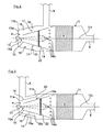
- Mehrere Ausführungsbeispiele der Erfindung sind im Folgenden mit weiteren Einzelheiten näher erläutert. Die schematische Zeichnung zeigt in:
- Fig. 1
- stark abstrahiert eine Abgasanlage für Brennkraftmaschinen in Kraftfahrzeugen, mit einem in eine Zweigleitung eingeschalteten Hydrolysekatalysator als Reduktionsmittelzersetzungskatalysator, einer Dosiereinrichtung für ein Reduktionsmittel und einem stromab dazu angeordneten SCR-Katalysator,
- Fig. 2
- den Hydrolysekatalysator gemäß
Fig. 1 mit vorgeschalteter Einlaufstrecke und einer Düse der Dosiereinrichtung in ver- größerter Darstellung, - Fig. 3
- eine alternative Ausgestaltung des Hydrolysekatalysators gemäß
Fig. 2 mit einem weiteren Gasführungsrohr, - Fig. 4
- eine alternative Ausgestaltung des Hydrolysekatalysators mit einem im Bereich einer Einlassöffnung eines Einlasstrichters angeordneten Umlenkblech,
- Fig. 5
- schematisch eine Vorderansicht der Einlassöffnung des Einlauf- trichters mit dort angeordnetem Umlenkblech sowie mit nicht rechtwinkliger, außermittiger Abgasstromzuführung im Bereich der Einlaufstrecke;
- Fig. 6
- eine alternative Ausgestaltung des Hydrolysekatalysators mit außermittig versetzter Düse.
- In der
Fig. 1 ist mit dem Bezugszeichen 1 eine nur angedeutete Brennkraftmaschine bezeichnet, deren Abgase aus den hier vier Brennräumen über einen Abgaskrümmer 2 einer Abgasleitung 3 zugeleitet werden. - In der Abgasleitung 3 sind in Strömungsrichtung des Abgases ein Oxidationskatalysator 4, ein Partikelfilter 5 und schließlich ein SCR-Katalysator 6 mit einem NH3-Sperrkatalysator 7 angeordnet. Soweit nicht beschrieben sind diese Abgasnachbehandlungsvorrichtungen 4, 5, 6, 7 geläufiger Konstruktion und Bauart.
- Stromauf des Oxidationskatalysators 4 ist an die Abgasleitung 3 eine Zweigleitung 8 angeschlossen, die stromab des Partikelfilters 5 und stromauf des SCR-Katalysators 6 wieder in die Abgasleitung 3 zurückgeführt ist.
- In der Zweigleitung 8 ist ein Hydrolysekatalysator 9 mit einer vorgeschalteten, Einlaufstrecke 10 vorgesehen, die in einem gemeinsamen, etwa zylindrischen Gehäuse 11 angeordnet sind. Das Gehäuse 11 ist mittels einer Wärmedämmschicht 12 nach außen thermisch isoliert.
- An der Stirnseite 11a des Gehäuses 11 ragt eine Düse 13 ein, mittels der über eine nicht dargestellte Dosiereinrichtung als Reduktionsmittel zum Beispiel eine wässrige Harnstofflösung eindosiert wird.
- Die
Fig. 2 zeigt den Hydrolysekatalysator 9 mit vorgeschalteter Einlaufstrecke 10, die in dem gemeinsamen Gehäuse 11 (ohne Wärmedämmschicht 12 gezeichnet) angeordnet sind. - Dabei mündet die Zweigleitung 8 in Nähe des Hydrolysekatalysators 9 radial in einen stromauf liegenden, an die Stirnwand 11a anschließenden, konischen Gehäuseabschnitt 11 b außerhalb eines konischen Einlauftrichters 14. Der Einlauftrichter 14 verjüngt sich von einem zum Hydrolysekatalysator 9 gleichen Strömungsquerschnitt ausgehend in Richtung zur Stirnwand 11a des Gehäuses 11 und endet dort als Drosselstelle mit wesentlich kleinerem Öffnungsquerschnitt in einer Einlassöffnung 15, die einen definierten Spaltabstand a zur Stirnwand 11a bzw. zu der dort einragenden Düse 13 der Dosiereinrichtung aufweist.
- Der Strömungsquerschnitt in der Einlaufstrecke 10 außerhalb des Einlauftrichters 14 ist hier kleiner ausgebildet als der Strömungsquerschnitt innerhalb des Einlauftrichters 14, was neben einer möglichst kompakten Bauform u.a. auch eine hohe Strömungsgeschwindigkeit des Abgases im Bereich der Düse 13 sowie weiter, innerhalb des Einlauftrichters 14 eine Strömungsberuhigung bzw. Vergleichmäßigung mit homogener Verteilung des Reduktionsmittels bewirkt.
- Die Düse 13 ist wie ersichtlich an der Stirnwand 11a, dem Einlauftrichter 14 gegenüberliegend sowie hier beispielhaft auf dessen Längsmittelachse 11c positioniert, so dass sich der Düsenstrahl 13a gleichmäßig innerhalb des Einlauftrichters 14 verteilen kann.
- Lediglich beispielhaft ist hier zudem im Einlauftrichter 14 noch ein Verdampfer und/oder Mischer 22 angeordnet, der einen definierten Abstand von der Einlassöffnung 15 aufweist, bevorzugt in etwa nach 2/3 der Rohrlänge des Einlassrohrs 14, von der Einlassöffnung 15 aus gesehen, eingesetzt ist.
- Außerhalb des Einlauftrichters 14 und etwa mittig zu dessen Länge (um einen möglichst großen Abstand zur Einlassöffnung 15 aufzuweisen) ist an dem konisch ausgeführten Gehäuseabschnitt 11b eine durch eine Ringwand und/oder Lochblech 16 gebildete Drosselstelle 17 vorgesehen, die den Strömungsquerschnitt in diesem Bereich entsprechend vermindert.
- Ferner sind hier optional und umfangsverteilt um den Einlauftrichter 14 sowie in Nähe der Einströmfläche des Hydrolysekatalysators 9 Bypassöffnungen 14a in den Einlauftrichter 14 eingearbeitet, die zum Beispiel kreis- oder schlitzförmig ausgebildet sein können.
- Der über die Zweigleitung 8 abgeleitete Abgasteilstrom strömt radial in den außerhalb des Einlauftrichters 14 und zwischen dem Gehäuseabschnitt 11a gebildeten Ringraum 18 ein, dessen durchströmtes Volumen kleiner als das durchströmte Volumen innerhalb des Einlauftrichters 14 ausgeführt sein kann. Durch die durch eine Ringwand und/oder ein Lochblech 16 gebildete Drosselstelle 17 wird die Gleichverteilung der Strömung noch verbessert.
- Der damit verbundene Druckanstieg stromauf der Drosselstelle 17 bewirkt ferner, dass ein definierter Anteil der Abgasteilmenge über die Bypassöffnungen 14a direkt auf den Hydrolysekatalysator 9 geleitet wird, wodurch die Vergleichmäßigung des Abgasstroms noch weiter verbessert wird.
- Das einströmende, heiße Abgas heizt von außen bereits den Einlauftrichter 14 auf, bevor es als weiteren Abschnitt der thermischen Einlaufstrecke 10 an der eine Drosselstelle ausbildenden Einlassöffnung 15 in einem Strömungsumlenkbereich 15a um ca. 180° umgelenkt und nunmehr innerhalb des Einlauftrichters 14 im Gegenstrom mit zunehmendem Strömungsquerschnitt und damit bedingter abnehmender Strömungsgeschwindigkeit dem Hydrolysekatalysator 9 zugeführt wird. Im Strömungsumlenkbereich 15a wird dazu über die Düse 13 und die Dosiereinrichtung die wässrige Harnstofflösung zugedüst.
- Im Einlauftrichter 14 und im Hydrolysekatalysator 9 wird der zudosierte Harnstoff mittels Thermolyse und Hydrolyse zu NH3 (Ammoniak) zersetzt und über die abgehende Zweigleitung 8 wieder der Abgasleitung 3 stromauf des SCR-Katalysators 6 zugeführt, in dem mittels des Reduktionsmittels NH3 die im gesamten Abgas enthaltenen Stickoxide zu Stickstoff und Wasserdampf reduziert werden. Der NH3-Sperrkatalysator 7 schließlich verhindert eine gegebenenfalls auftretende Emission von NH3 in die Atmosphäre.
- Der Einlauftrichter 14 ist zum Beispiel an seinen Innenwänden analog zum Hydrolysekatalysator 9 mit zum Beispiel TiO2 katalytisch wirksam beschichtet, um gegebenenfalls auftretenden Rückständen und Ablagerungen von Harnstoff, insbesondere bei noch nicht ausreichend hohen Abgastemperaturen, entgegenzuwirken.
- Die
Fig. 3 zeigt eine alternative Ausführung der vorgeschalteten Einlaufstrecke 10 des Hydrolysekatalysators 9 innerhalb des Gehäuses 11 und ist nur soweit beschrieben, als sie sich von der Ausführung gemäßFig. 2 unterscheidet. Funktionell gleiche Teile sind mit gleichen Bezugszeichen versehen. - Abweichend zur
Fig. 2 mündet die das Abgas zuführende Zweigleitung 8 hier mehr im Bereich der Stirnwand 11a des Gehäuses 11 in den Gehäuseabschnitt 11 b ein. - An der Stirnwand 11a ist ferner ein konisches Gasführungsrohr 19 befestigt, das in etwa parallel bzw. mit in etwa ähnlichem Konuswinkel sowie im Wesentlichen symmetrisch zum Einlauftrichter 14 etwa über dessen halbe Länge verläuft und somit den Ringraum 18 außerhalb des Einlauftrichters 14 in zwei Strömungswege 18a und 18b unterteilt.
- Das über die Zweigleitung 8 zugeführte Abgas strömt somit unter zweifacher Umlenkung in den Strömungsumlenkbereichen 15a und 15b, nämlich einmal an der freien Stirnseite 20 des Gasführungsrohres 19 und das zweitemal an der Einlassöffnung 15 des Einlauftrichters 14, in den Einlauftrichter 14 und dann in den Hydrolysekatalysator 9. Es ist offensichtlich, dass durch den Einsatz des Gasführungsrohres 19 die Einlaufstrecke 10 bei geringstem Bauraum nochmals vergrößert ist.
- Ein Anteil der Abgasmenge kann auch hier wiederum über die optionalen Bypassöffnungen 14a direkt über den Strömungsweg 18a zum Hydrolysekatalysator 9 strömen.
- Wie bereits zuvor ausgeführt, kann der Einlauftrichter 14 gemäß den
Fig. 2 und 3 gegebenenfalls auch ohne Bypassöffnungen 14a aufgeführt sein, so dass eine direkte Anströmung des Hydrolysekatalysators 9 unterbunden ist und die gesamte Abgasteilströmung über die Einlaufstrecke 10 geleitet ist. - Die
Fig. 4 zeigt eine weitere alternative Ausführung und ist nur soweit beschrieben, als sie sich von der Ausführung gemäßFig. 2 und 3 unterscheidet. Funktionell gleiche Teile sind mit gleichen Bezugszeichen versehen. Insbesondere zeigt dieFig. 4 hier beispielhaft die Verwendung von Umlenkblechen 15c im Bereich der Einlassöffnung 15 des Einlauftrichters 14, die zur Erhöhung der Turbulenz, stromab der Zuführung für das Reduktionsmittel dienen. Im Gegensatz zum Verdampfer bzw. Mischer 22 sind die Umlenkbleche 15c so positioniert, dass das Reduktionsmittel nicht auf diese trifft, um Ablagerungen an diesen Bauteilen zu vermeiden. - Die Umlenkbleche können beliebige Geometrien aufweisen. Besonders bevorzugt ist eine zacken-, fächer- oder ringförmige Geometrie. In der
Fig. 5 ist eine Draufsicht auf den Einlauftrichter 14 mit hier lediglich beispielhaft zwei halbkreisförmigen Umlenkblechen 15c gezeigt, die hier kreuzschraffiert dargestellt sind. Zusätzlich ist eine Zuführung 8' des Abgases dargestellt, die außermittig gegenüber den Mittelachsen M1, M2 versetzt und/oder geneigt, das heißt zum Beispiel nicht im rechten Winkel, zum Umfang des Gehäuses der Einlaufstrecke 10 erfolgt. Hierdurch wird der Abgasströmung ein Drall aufgeprägt, über den die Verteilung des Abgases und des Reduktionsmittels beeinflusst werden kann. - In der
Fig. 6 ist schließlich eine Ausführungsform gezeigt, bei der die Düse 13 außermittig versetzt zur Längsmittelachse 11c des Einlassrohrs 14 einspritzt, wodurch eine Anpassung der lokalen Reduktionsmittelmenge an die Strömungsgeschwindigkeiten erfolgt , was zu einer guten Vermischung von Reduktionsmittel und Abgasstrom beiträgt. Selbstverständlich kann ein derartiger Aufbau mit außermittig versetzter Düse 13 grundsätzlich auch bei der Ausgestaltung nachFig. 2, 3 und4 vorgesehen werden. Ebenso ist es selbstverständlich möglich, die Düsenpositionierung der Ausgestaltung nach z.B.Fig. 2 auf die Ausgestaltung derFig. 6 zu übertragen. - Gemäß
Fig. 1 ist in der Zweigleitung 8 ferner stromauf des Hydrolysekatalysators 9 ein steuerbares Drosselventil 21 eingesetzt, das nach Maßgabe von Betriebsparametern der Brennkraftmaschine 1, wie zum Beispiel Lastanforderung, Drehzahl, Temperatur, etc., die abgezweigte Abgasteilmenge steuert, so dass deren Durchsatz mehr oder minder an die jeweils anstehenden Gesamtabgasmenge anpassbar ist. - Es kann gegebenenfalls aber auch ausreichend sein, wenn der funktionsbedingt einen Abgasgegendruck erzeugende Oxidationskatalysator 4 und der Dieselpartikelfilter 5 als Drosseleinrichtungen genutzt werden, indem die Zweigleitung 8 entsprechend stromauf abzweigt und stromab wieder in die Abgasleitung 3 einmündet.
- Als weitere Drosseleinrichtung bei einer aufgeladenen Brennkraftmaschine mit in dem Abgasstrang befindlicher Abgasturbine T des Abgasturboladers (lediglich äußerst schematisch und strichliert in
Fig. 1 dargestellt) kann die Zweigleitung 8 auch stromauf der Abgasturbine an die Abgasleitung 3 angeschlossen sein. - Weist die Brennkraftmaschine 1 zum Beispiel eine geteilte Abgasführung mit zugeordneten Zylindergruppen oder bei einer V-Brennkraftmaschine mit zugeordneten Zylinderbänken auf, so dass zum Beispiel zwei Abgaskrümmer 2 und Abgasleitungen 3 mit entsprechenden Abgasturboladern und/oder Katalysatoren 4, 5, 6, 7 vorhanden sind, so kann die Zweigleitung 8 mit dem Hydrolysekatalysator 9 und der Einlaufstrecke 10 bevorzugt von einer der Abgasleitungen 3 abgehen. Dies hat den Vorteil, dass diese Zylindergruppe oder Zylinderbank über ein Motorsteuergerät so betrieben werden kann, dass in diesem Abgasstrang abhängig von Betriebsparametern wie Kaltstart, Leerlauf oder Niedriglast die Abgastemperatur angehoben wird, um eine früh einsetzende, wirkungsvolle Zersetzung des zudosierten Reduktionsmittels bzw. der Harnstofflösung zu erreichen. Die andere Zylindergruppe oder Zylinderbank kann wirkungsgradoptimiert und/oder bei niedriger Last betrieben werden.
- Die abgezweigte Abgasteilmenge wird nach deren Behandlung im Hydrolysekatalysator 9 beiden aufgeteilten Abgassträngen bzw. beiden Abgasleitungen 3 stromauf der SCR-Katalysatoren 6 zugeführt.
- Die aufgeteilte Abgasanlage kann aber auch so ausgeführt sein, dass sie vor einem einzigen SCR-Katalysator 6 wieder zu einer Abgasleitung 3 zusammengeführt ist.
- Es sei bemerkt, dass die Anordnung des Hydrolysekatalysators 9 mit der Einlaufstrecke 10 nicht wie dargestellt in einem separaten Gehäuse 11 ausgeführt sein muss. Die Bauteile 9 und 10 können gegebenenfalls auch mit dem Oxidationskatalysator 4 und/oder dem Dieselpartikelfilter 5 in einem Gehäuse zusammengebaut sein.
- Für den Oxidationskatalysator 4 zur Oxidation von Stickstoffmonoxid wird bevorzugt Platin und/oder Palladium und/oder Rhodium und/oder Cer und/oder deren Oxide und/oder Zeolithe als aktive katalytische Materialien eingesetzt. Als Aktivkomponenten für die SCR-Katalysatoren zur Reduktion von Stickoxiden mit Hilfe von Ammoniak kommen in vorteilhafter Weise Vanadium und/oder Vanadiumpentoxid und/oder Titandioxid und/oder Wolframoxid und/oder kupferhaltige Zeolithe und/oder eisenhaltige Zeolithe und/oder cobalthaltige Zeolithe zum Einsatz.
Claims (12)
- Vorrichtung zur Nachbehandlung von Abgasen in einer Abgasanlage von Brennkraftmaschinen, insbesondere von magerlauffähigen Brennkraftmaschinen für Kraftfahrzeuge, mit wenigstens einem in den Abgasstrom geschalteten Reduktionsmittelzersetzungskatalysator, insbesondere einem Hydrolysekatalysator, und einer stromauf hierzu in einer Abgasleitung angeordneten Dosiereinrichtung zur Zuführung von Reduktionsmittel, insbesondere zur Zuführung einer wässrigen Harnstofflösung, wobei dem Reduktionsmittelzersetzungskatalysator bevorzugt wenigstens eine weitere Katalysatoreinrichtung, insbesondere wenigstens ein SCR-Katalysator, nachgeschaltet ist, dadurch gekennzeichnet, dass dem Reduktionsmittelzersetzungskatalysator (9) eine wenigstens einen Strömungsumlenkbereich (15a, 15b) aufweisende Einlaufstrecke (10) für das Abgas vorgeschaltet ist, die so ausgebildet ist, dass das Abgas radial außerhalb eines an den Reduktionsmittelzersetzungskatalysator (9) anschließenden Einlassrohrs (14) in einem das Einlassrohr (14) umgebenden Gehäuseabschnitt (11a, 11b) zugeführt und im Gegenstrom über eine stirnseitige Einlassöffnung (15) des Einlassrohrs (14) zum Reduktionsmittelzersetzungskatalysator (9) geführt ist, wobei das Reduktionsmittel im der Einlassöffnung (15) zugeordneten Strömungsumlenkbereich (15a) des Abgasstromes zugeführt wird.
- Vorrichtung nach Anspruch 1, dadurch gekennzeichnet, dass im Bereich der Einlaufstrecke (10) stromauf der Zuführung des Reduktionsmittels wenigstens eine Drosseleinrichtung (17) zur Drosselung oder Androsselung des Abgasstroms vorgesehen ist.
- Vorrichtung nach Anspruch 1 oder 2, dadurch gekennzeichnet, dass im Bereich der Einlaufstrecke (10) stromauf der Zuführung des Reduktionsmittels der Strömungsquerschnitt kleiner ist als stromab der Zuführung des Reduktionsmittels und/oder dass das durchströmte Volumen in der Einlaufstrecke (10) außerhalb des Einlassrohrs (14) kleiner ist als das durchströmte Volumen innerhalb eines definierten Einlassbereiches des Einlassrohrs (14).
- Vorrichtung nach einem der Ansprüche 1 bis 3, dadurch gekennzeichnet, dass eine Düse (13) der Dosiereinrichtung zum Zuführen des Reduktionsmittels im der Einlassöffnung (15) zugeordneten Strömungsumlenkbereich (15a) angeordnet und/oder auf die Einlassöffnung (15) gerichtet ist, wobei bevorzugt vorgesehen ist, dass die Düse (13) an einer Stirnwand (11a) des das Einlassrohr (14) umgebenden Gehäuseabschnittes (11 b), der Einlassöffnung (15) des Einlassrohrs(14) in einem definierten Abstand (a) gegenüberliegend angeordnet ist und/oder dass die Düse (13) hinsichtlich ihrer Einspritzrichtung in die Einlassöffnung (15) des Einlassrohrs (14) koaxial oder außermittig versetzt zur Längsmittelachse (11 c) des Einlassrohrs (14) angeordnet ist.
- Vorrichtung nach einem der Ansprüche 1 bis 4, dadurch gekennzeichnet, dass stromab der Zuführung für das Reduktionsmittel wenigstens ein Mittel (15c), bevorzugt wenigstens ein Umlenkblech, zur Umlenkung der Strömung und/oder Erhöhung der Turbulenz vorgesehen oder angebracht ist, wobei bevorzugt vorgesehen ist, dass das wenigstens eine Mittel (15c) zur Umlenkung der Strömung und/oder Erhöhung der Turbulenz wenigstens bereichsweise um oder entlang der Einlassöffnung (15) ausgebildet oder angeordnet ist und/oder dass das wenigstens eine Mittel (15c) zur Umlenkung der Strömung und/oder Erhöhung der Turbulenz so ausgebildet oder angeordnet ist, dass das insbesondere mittels einer Düse (13) zudosierte Reduktionsmittel nicht auf dieses auftrifft.
- Vorrichtung nach einem der Ansprüche 1 bis 5, dadurch gekennzeichnet, dass in denjenigen Bereichen, in denen eine definiert hohe Reduktionsmittelkonzentration oder Reduktionsmittelmenge vorliegt, die Strömungsgeschwindigkeit durch Einbauten und/oder querschnittsverändernde Maßnahmen gegenüber denjenigen Bereichen, in denen eine demgegenüber niedrigere Reduktionsmittelkonzentration oder Reduktionsmittelmenge vorliegt, erhöht ist.
- Vorrichtung nach einem der Ansprüche 1 bis 6, dadurch gekennzeichnet, dass stromab der Zuführung für das Reduktionsmittel ein Verdampfer und/oder Mischer (22) angebracht ist, bevorzugt im Einlassrohr (14) ein Verdampfer und/oder Mischer (22) angeordnet ist, der einen definierten Abstand von der Einlassöffnung (15) aufweist, bevorzugt in etwa nach 2/3 der Rohrlänge des Einlassrohrs (14), von der Einlassöffnung (15) aus gesehen, eingesetzt ist.
- Vorrichtung nach einem der Ansprüche 1 bis 7, dadurch gekennzeichnet, dass an dem Einlassrohr (14) wenigstens eine Bypassöffnung ausgebildet ist, bevorzugt mehrere, insbesondere umfangsverteilte Bypassöffnungen (14a) ausgebildet sind.
- Vorrichtung nach einem der Ansprüche 1 bis 8, dadurch gekennzeichnet, dass in dem das Einlassrohr (14) radial umgebenden Gehäuseabschnitt (11b) stromauf des der Einlassöffnung (15) zugeordneten Strömungsumlenkbereichs (15a) und damit stromauf der Reduktionsmittelzuführung (13) sowie außerhalb des Einlassrohrs (14) zumindest eine weitere Drosselstelle (17) für das einströmende Abgas vorgesehen ist.
- Vorrichtung nach Anspruch 8 oder 9, dadurch gekennzeichnet, dass die Drosselstelle (17) einen definierten Abstand von der Einlassöffnung (15) des Einlassrohrs (14) und/oder der wenigstens einen Bypassöffnung (14a) aufweist, insbesondere in etwa auf halber Wegstrecke zwischen der wenigstens einen Bypassöffnung (14a) und der Einlassöffnung (15) angeordnet ist und/oder dass die Drosselstelle (17) durch wenigstens eine, in einem das Einlassrohr (14) umgebenden Ringraum (18) ausgebildete Querschnittsverengung gebildet ist, welche Querschnittsverengung insbesondere durch eine einen Durchströmspalt freigebende Ringwand und/oder ein Lochblech (16) gebildet ist.
- Vorrichtung nach einem der Ansprüche 1 bis 10, dadurch gekennzeichnet, dass im Gehäuseabschnitt (11 b) radial außerhalb des Einlassrohrs (14) zumindest ein weiteres Gasführungsrohr (19) angeordnet ist, das eine mäanderförmige Gasströmung mit mehrfacher Umlenkung des Abgasstromes zwischen der radial einmündenden Abgasleitung (8) und dem Reduktionsmittelzersetzungskatalysator (9) bzw. innerhalb der Einlaufstrecke (10) bewirkt, wobei bevorzugt vorgesehen ist, dass das zumindest eine weitere Gasführungsrohr (19) an einer Stirnwand (11a) des das Einlassrohr (14) umgebenden Gehäuseabschnittes (11b) befestigt ist und/oder im Wesentlichen parallel zum Einlassrohr (14) verläuft, insbesondere einen im Wesentlichen gleichen Konuswinkel wie das Einlassrohr (14) aufweist und/oder dass das zumindest eine weitere Gasführungsrohr (19) durch mehrere ineinandergeschachtelte und/oder miteinander verbundene Rohre, insbesondere durch mehrere ineinandergeschachtelte und/oder miteinander verbundene Konusrohre, gebildet ist.
- Vorrichtung nach einem der Ansprüche 1 bis 11, dadurch gekennzeichnet, dass die Zuführung (8') des Abgases in das, die Einlaufstrecke (10) umgebende Gehäuse unter einem Winkel geneigt zum Gehäuse erfolgt, insbesondere nicht im rechten Winkel zum Gehäuse erfolgt, und/oder außermittig versetzt zu Gehäusemittelachsen erfolgt.
Applications Claiming Priority (1)
| Application Number | Priority Date | Filing Date | Title |
|---|---|---|---|
| DE102009053950A DE102009053950A1 (de) | 2009-11-19 | 2009-11-19 | Vorrichtung zur Nachbehandlung von Abgasen von Brennkraftmaschinen |
Publications (2)
| Publication Number | Publication Date |
|---|---|
| EP2325452A1 true EP2325452A1 (de) | 2011-05-25 |
| EP2325452B1 EP2325452B1 (de) | 2015-05-27 |
Family
ID=43264721
Family Applications (1)
| Application Number | Title | Priority Date | Filing Date |
|---|---|---|---|
| EP10010243.3A Active EP2325452B1 (de) | 2009-11-19 | 2010-09-23 | Vorrichtung zur Nachbehandlung von Abgasen von Brennkraftmaschinen |
Country Status (6)
| Country | Link |
|---|---|
| US (1) | US8726640B2 (de) |
| EP (1) | EP2325452B1 (de) |
| CN (1) | CN102071994B (de) |
| BR (1) | BRPI1004807B1 (de) |
| DE (1) | DE102009053950A1 (de) |
| RU (1) | RU2455504C1 (de) |
Cited By (20)
| Publication number | Priority date | Publication date | Assignee | Title |
|---|---|---|---|---|
| DE202012011764U1 (de) | 2012-12-07 | 2013-01-30 | Eberspächer Catem Gmbh & Co. Kg | Mischer zur Nachbehandlung von Abgasen |
| WO2013160639A1 (en) * | 2012-04-24 | 2013-10-31 | Perkins Engines Company Limited | Emissions cleaning module |
| CN103874912A (zh) * | 2011-10-12 | 2014-06-18 | 株式会社堀场制作所 | 气体分析装置 |
| DE102013005206B3 (de) * | 2013-03-08 | 2014-06-26 | Eberspächer Exhaust Technology GmbH & Co. KG | Einströmkammer für einen Katalysator einer Abgasreinigungsanlage |
| EP2627881A4 (de) * | 2010-10-14 | 2014-07-02 | Scania Cv Abp | Anordnung zur einspeisung eines flüssigen mediums in abgase aus einem verbrennungsmotor |
| EP2622184A4 (de) * | 2010-09-30 | 2014-07-09 | Scania Cv Ab | Anordnung zur einspeisung eines flüssigen mediums in abgase aus einem verbrennungsmotor |
| CN104121081A (zh) * | 2014-07-02 | 2014-10-29 | 潍柴动力股份有限公司 | 一种scr尾气处理系统的进气管、scr尾气处理系统 |
| WO2015192926A1 (de) * | 2014-06-17 | 2015-12-23 | Daimler Ag | Mischvorrichtung eines abgasreinigungssystems einer kraftfahrzeug-brennkraftmaschine |
| WO2015197331A1 (de) * | 2014-06-25 | 2015-12-30 | Twintec Technologie Gmbh | Vorrichtung zur erzeugung von ammoniak |
| WO2016169709A1 (de) * | 2015-04-21 | 2016-10-27 | Friedrich Boysen Gmbh & Co. Kg | Vorrichtung zum einbringen eines fluids in einen gasstrom |
| CN106414931A (zh) * | 2014-06-03 | 2017-02-15 | 佛吉亚排放控制技术美国有限公司 | 混合器与计量给料器锥形件的组件 |
| US9664081B2 (en) | 2007-07-24 | 2017-05-30 | Faurecia Emissions Control Technologies, Germany Gmbh | Assembly and method for introducing a reducing agent into the exhaust pipe of an exhaust system of an internal combustion engine |
| US9714598B2 (en) | 2015-04-30 | 2017-07-25 | Faurecia Emissions Control Technologies, Usa, Llc | Mixer with integrated doser cone |
| US9719397B2 (en) | 2015-04-30 | 2017-08-01 | Faurecia Emissions Control Technologies Usa, Llc | Mixer with integrated doser cone |
| US9726064B2 (en) | 2015-04-30 | 2017-08-08 | Faurecia Emissions Control Technologies, Usa, Llc | Mixer for use in a vehicle exhaust system |
| US9828897B2 (en) | 2015-04-30 | 2017-11-28 | Faurecia Emissions Control Technologies Usa, Llc | Mixer for a vehicle exhaust system |
| EP3189219A4 (de) * | 2014-09-03 | 2018-02-07 | Scania CV AB | Anordnung zum einbringen eines reduktionsmittels in einem abgasstrom |
| EP2339137B2 (de) † | 2009-12-16 | 2018-09-26 | FPT Motorenforschung AG | Abgassystem für Verbrennungsmotor |
| US10933387B2 (en) | 2016-10-21 | 2021-03-02 | Faurecia Emissions Control Technologies, Usa, Llc | Reducing agent mixer |
| EP4063626A1 (de) * | 2021-03-25 | 2022-09-28 | Purem GmbH | Abgas/reaktionsmittel-mischbaugruppe |
Families Citing this family (69)
| Publication number | Priority date | Publication date | Assignee | Title |
|---|---|---|---|---|
| US8499548B2 (en) | 2008-12-17 | 2013-08-06 | Donaldson Company, Inc. | Flow device for an exhaust system |
| US8539761B2 (en) | 2010-01-12 | 2013-09-24 | Donaldson Company, Inc. | Flow device for exhaust treatment system |
| EP3267005B2 (de) | 2010-06-22 | 2023-12-27 | Donaldson Company, Inc. | Abgasnachbehandlungsvorrichtung |
| DE102011005654A1 (de) * | 2011-03-16 | 2012-09-20 | Man Diesel & Turbo Se | Brennkraftmaschine |
| US9120489B2 (en) * | 2011-06-03 | 2015-09-01 | General Electric Company | Systems and methods for an engine |
| US9404448B2 (en) | 2011-06-03 | 2016-08-02 | General Electric Company | Systems and methods for an engine |
| US8863886B2 (en) * | 2011-07-29 | 2014-10-21 | Magna International Inc. | Hybrid fascia mounted exhaust tip assembly |
| CN102536399A (zh) * | 2011-12-31 | 2012-07-04 | 杭州银轮科技有限公司 | 一种用于柴油机尾气后处理的scr催化转化器 |
| CN103362605B (zh) * | 2012-03-30 | 2016-05-18 | 曼柴油机和涡轮机欧洲股份公司 | 内燃机 |
| US8938954B2 (en) * | 2012-04-19 | 2015-01-27 | Donaldson Company, Inc. | Integrated exhaust treatment device having compact configuration |
| DE102012010878B4 (de) | 2012-06-01 | 2025-01-23 | Daimler Truck AG | Reduktionsmittelzugabe- und Aufbereitungssystem eines Kraftfahrzeugs |
| DE102013208743B4 (de) | 2012-06-15 | 2015-06-18 | Ford Global Technologies, Llc | Vorrichtung zur Abgasnachbehandlung |
| US9267413B2 (en) * | 2012-06-20 | 2016-02-23 | Cnh Industrial America Llc | Exhaust system for an agricultural vehicle |
| DE102012014334A1 (de) * | 2012-07-20 | 2014-05-15 | Man Truck & Bus Ag | Mischvorrichtung zur Nachbehandlung von Abgasen |
| DE102012014333A1 (de) | 2012-07-20 | 2014-01-23 | Man Truck & Bus Ag | Mischvorrichtung zur Nachbehandlung von Abgasen |
| JP6026256B2 (ja) * | 2012-12-11 | 2016-11-16 | ボルボトラックコーポレーション | 内燃機関の排気浄化装置 |
| CA2900801C (en) | 2013-02-15 | 2021-01-26 | Donaldson Company, Inc. | Dosing and mixing arrangement for use in exhaust aftertreatment |
| GB2512896B (en) * | 2013-04-10 | 2016-05-25 | Perkins Engines Co Ltd | A mixer module and an emissions cleaning module |
| GB2512934C (en) * | 2013-04-12 | 2020-03-11 | Eminox Ltd | Reductant injection in an exhaust system |
| DE102013104579B4 (de) * | 2013-05-03 | 2016-12-22 | Eberspächer Exhaust Technology GmbH & Co. KG | Einströmkammer für einen katalysator einer abgasreinigungsanlage |
| DE102013009417A1 (de) * | 2013-06-05 | 2014-12-11 | Man Diesel & Turbo Se | Ammoniakgenerator |
| US9145818B2 (en) * | 2013-06-12 | 2015-09-29 | Deere & Company | Exhaust gas sampling device |
| KR101445038B1 (ko) * | 2013-06-28 | 2014-09-26 | 두산엔진주식회사 | 선택적 촉매 환원 및 촉매 재생 시스템 |
| DE202013006962U1 (de) | 2013-08-05 | 2013-08-28 | Tenneco Gmbh | Mischkammer |
| US9109486B2 (en) * | 2013-09-19 | 2015-08-18 | Caterpillar Inc. | System and method for reductant injection |
| US20150198073A1 (en) * | 2014-01-13 | 2015-07-16 | Caterpillar, Inc. | Exhaust aftertreatment system with in-elbow reductant injection |
| EP3498995B1 (de) * | 2014-01-31 | 2020-09-09 | Donaldson Company, Inc. | Dosier- und mischanordnung zur verwendung bei der abgasnachbehandlung |
| US10273851B2 (en) | 2014-02-28 | 2019-04-30 | Scania Cv Ab | Exhaust treatment system and method for treatment of an exhaust stream |
| US20150337702A1 (en) * | 2014-05-23 | 2015-11-26 | Tenneco Automotive Operating Company Inc. | Exhaust aftertreatment system with low-temperature scr |
| DE102014108877A1 (de) * | 2014-06-25 | 2015-12-31 | Twintec Technologie Gmbh | Vorrichtung und Verfahren zur Erzeugung von Ammoniak zur Abgasnachbehandlung |
| US10392994B2 (en) | 2014-12-05 | 2019-08-27 | Cummins, Inc. | Reductant injection exhaust manifold |
| GB2590579B (en) * | 2014-12-31 | 2021-12-01 | Cummins Emission Solutions Inc | Single module integrated aftertreatment module |
| US9784163B2 (en) | 2015-01-22 | 2017-10-10 | Tenneco Automotive Operating Company Inc. | Exhaust aftertreatment system having mixer assembly |
| DE102015002432A1 (de) | 2015-02-26 | 2016-09-01 | Daimler Ag | Abgasnachbehandlungseinrichtung für eine Verbrennungskraftmaschine eines Kraftwagens |
| DE102015103425B3 (de) | 2015-03-09 | 2016-05-19 | Tenneco Gmbh | Mischvorrichtung |
| DE102015104540B3 (de) * | 2015-03-25 | 2016-02-04 | Tenneco Gmbh | Mischvorrichtung |
| WO2016158993A1 (ja) * | 2015-03-30 | 2016-10-06 | いすゞ自動車株式会社 | 排気浄化ユニット |
| SE539803C2 (en) | 2015-06-05 | 2017-12-05 | Scania Cv Ab | A method and a system for determining a composition of a gas mix in a vehicle |
| DE102015114723A1 (de) * | 2015-09-03 | 2017-03-09 | Eberspächer Exhaust Technology GmbH & Co. KG | Abgasanlage für eine Brennkraftmaschine |
| US9689290B2 (en) * | 2015-12-01 | 2017-06-27 | GM Global Technology Operations LLC | Reductant mixing system for an exhaust gas after-treatment device |
| RU2617644C1 (ru) * | 2015-12-17 | 2017-04-25 | Федеральное государственное унитарное предприятие "Центральный ордена Трудового Красного Знамени научно-исследовательский автомобильный и автомоторный институт "НАМИ" | Устройство очистки отработавших газов двигателя |
| JP6676438B2 (ja) | 2016-03-30 | 2020-04-08 | 日本碍子株式会社 | 還元剤噴射装置、排ガス処理方法、及び排ガス処理装置 |
| US9890682B2 (en) * | 2016-04-08 | 2018-02-13 | Caterpillar Inc. | System, apparatus, and method to address unwanted DEF-based deposits in diesel exhaust system |
| SE539834C2 (en) * | 2016-04-11 | 2017-12-12 | Scania Cv Ab | An injection arrangement for injection of a urea solution into an exhaust gas passage |
| US10125646B2 (en) * | 2016-04-13 | 2018-11-13 | Johnson Matthey Public Limited Company | Exhaust system for a diesel engine |
| US10174658B2 (en) * | 2016-07-20 | 2019-01-08 | Faurecia Emissions Control Technologies, Usa, Llc | Flow diverter to mitigate deposits in a doser cone |
| CN106194351B (zh) * | 2016-08-10 | 2018-10-02 | 河北亿利橡塑集团有限公司 | 多层导流的scr催化消声系统功能化进气机构 |
| US10612442B2 (en) | 2016-08-22 | 2020-04-07 | Daimler Ag | Exhaust gas treatment device for an internal combustion engine of a motor vehicle |
| FR3059710B1 (fr) * | 2016-12-05 | 2020-10-30 | Aaqius & Aaqius Sa | Dispositif et procede d'injection d'un gaz a melanger dans une ligne d'echappement |
| US11028754B2 (en) | 2016-12-07 | 2021-06-08 | Cummins Emission Solutions Inc. | Real-time control of reductant droplet spray momentum and in-exhaust spray distribution |
| GB2558311A (en) * | 2016-12-30 | 2018-07-11 | Proventia Emission Control Oy | Flow distribution arrangement for aftertreatment of exhaust gas |
| CN110573706B (zh) * | 2017-04-28 | 2021-07-13 | 瓦锡兰芬兰有限公司 | 噪声衰减器和将还原剂引入到废气流中的方法 |
| US10329990B2 (en) * | 2017-08-04 | 2019-06-25 | Gm Global Technology Operations Llc. | Asymmetric catalyst cone for swirl induction of exhaust gas flow |
| CN107575882A (zh) * | 2017-09-26 | 2018-01-12 | 广州智光节能有限公司 | 一种余热锅炉scr烟气脱硝效率调节装置和方法 |
| DE102017124032A1 (de) * | 2017-10-16 | 2019-04-18 | Eberspächer Exhaust Technology GmbH & Co. KG | Abgas/Reaktionsmittel-Mischbaugruppe |
| DE102018202298A1 (de) * | 2018-02-15 | 2019-08-22 | Robert Bosch Gmbh | Abgasnachbehandlungseinrichtung zum Eindosieren eines flüssigen Abgasnachbehandlungsmittels |
| CN110344916A (zh) * | 2018-04-02 | 2019-10-18 | 天纳克(苏州)排放系统有限公司 | 进气锥及其尾气后处理装置 |
| WO2019194784A1 (en) | 2018-04-02 | 2019-10-10 | Cummins Emission Solutions Inc. | Aftertreatment system including noise reducing components |
| WO2020009694A1 (en) * | 2018-07-03 | 2020-01-09 | Cummins Emission Solutions Inc. | Body mixing decomposition reactor |
| CN114635773B (zh) * | 2018-07-06 | 2024-04-02 | 康明斯排放处理公司 | 用于后处理系统的分解室 |
| US10787946B2 (en) | 2018-09-19 | 2020-09-29 | Faurecia Emissions Control Technologies, Usa, Llc | Heated dosing mixer |
| DE102018124025A1 (de) * | 2018-09-28 | 2020-04-02 | Man Truck & Bus Se | Vorrichtung zum Zumischen eines flüssigen Reduktionsmittels zum Abgas einer Brennkraftmaschine und Kraftfahrzeug |
| DE102019006499A1 (de) * | 2019-09-16 | 2021-03-18 | Albonair Gmbh | Beheizte Einpritzdüse |
| DE102019128193A1 (de) * | 2019-10-18 | 2021-04-22 | Eberspächer Exhaust Technology GmbH | Mischeranordnung |
| DE102019008357B3 (de) * | 2019-12-02 | 2021-05-06 | Ford Global Technologies, Llc | Brennkraftmaschine mit Abgasturboaufladung und motornaher Abgasnachbehandlung |
| DE102021104274A1 (de) * | 2021-02-23 | 2022-08-25 | Friedrich Boysen GmbH & Co KG. | Heizsystem |
| DE102021119169B4 (de) | 2021-07-23 | 2024-06-13 | Tenneco Gmbh | Abgasteilanlage |
| WO2023235218A1 (en) * | 2022-05-30 | 2023-12-07 | Cummins Emission Solutions Inc. | Valve assembly for internal combustion engine system with turbomachinery |
| FI131990B1 (en) * | 2024-04-10 | 2026-03-27 | Proventia Oy | Exhaust gas countercurrent aftertreatment mixer |
Citations (5)
| Publication number | Priority date | Publication date | Assignee | Title |
|---|---|---|---|---|
| DE4038054A1 (de) | 1990-11-29 | 1992-06-04 | Man Technologie Gmbh | Verfahren und vorrichtung zur selektiven katalytischen no(pfeil abwaerts)x(pfeil abwaerts)-reduktion in sauerstoffhaltigen abgasen |
| DE4203807A1 (de) | 1990-11-29 | 1993-08-12 | Man Nutzfahrzeuge Ag | Vorrichtung zur katalytischen no(pfeil abwaerts)x(pfeil abwaerts)-reduktion |
| DE4308542A1 (de) | 1993-03-17 | 1994-09-22 | Man Nutzfahrzeuge Ag | Verfahren und Vorrichtung zur selektiven katalytischen Reduktion von NO¶x¶ in sauerstoffhaltigen Gasen |
| EP1052009A1 (de) | 1999-03-25 | 2000-11-15 | Man Nutzfahrzeuge Ag | Verfahren zur Behandlung von Abgasen einer Brennkraftmaschine unter Verwendung von Harnstoff |
| WO2010034651A1 (de) * | 2008-09-24 | 2010-04-01 | Emitec Gesellschaft Für Emissionstechnologie Mbh | Abgasreinigungssystem für dieselmotoren |
Family Cites Families (8)
| Publication number | Priority date | Publication date | Assignee | Title |
|---|---|---|---|---|
| DE4417238C2 (de) * | 1994-05-17 | 2003-03-27 | Siemens Ag | Einrichtung zur Minderung der Stickoxide im Abgas eines mit Luftüberschuß betriebenen Verbrennungsmotors |
| DE10206028A1 (de) * | 2002-02-14 | 2003-08-28 | Man Nutzfahrzeuge Ag | Verfahren und Vorrichtung zur Erzeugung von Ammoniak |
| US7581389B2 (en) * | 2004-01-13 | 2009-09-01 | Emcon Technologies Llc | Method and apparatus for monitoring ash accumulation in a particulate filter of an emission abatement assembly |
| US8015802B2 (en) * | 2004-11-25 | 2011-09-13 | Komatsu Ltd. | Exhaust gas purification device for internal combustion engine |
| FR2891305B1 (fr) * | 2005-09-27 | 2007-11-23 | Renault Sas | Ligne d'echappement de moteur de vehicule comprenant un injecteur de carburant |
| DE102006023145A1 (de) * | 2006-05-16 | 2007-11-22 | Emitec Gesellschaft Für Emissionstechnologie Mbh | Verfahren und Vorrichtung zur Aufbereitung des Abgases einer Verbrennungskraftmaschine |
| DE102006038291A1 (de) * | 2006-08-16 | 2008-02-21 | Man Nutzfahrzeuge Aktiengesellschaft | Abgasnachbehandlungssystem |
| DE102007049850B4 (de) * | 2007-10-18 | 2011-04-21 | Pierburg Gmbh | Abgasnachbehandlungssystem für eine Verbrennungskraftmaschine |
-
2009
- 2009-11-19 DE DE102009053950A patent/DE102009053950A1/de not_active Withdrawn
-
2010
- 2010-09-23 EP EP10010243.3A patent/EP2325452B1/de active Active
- 2010-11-11 BR BRPI1004807-3A patent/BRPI1004807B1/pt active IP Right Grant
- 2010-11-18 RU RU2010147256/06A patent/RU2455504C1/ru active IP Right Revival
- 2010-11-19 CN CN201010556509.6A patent/CN102071994B/zh active Active
- 2010-11-19 US US12/950,242 patent/US8726640B2/en active Active
Patent Citations (5)
| Publication number | Priority date | Publication date | Assignee | Title |
|---|---|---|---|---|
| DE4038054A1 (de) | 1990-11-29 | 1992-06-04 | Man Technologie Gmbh | Verfahren und vorrichtung zur selektiven katalytischen no(pfeil abwaerts)x(pfeil abwaerts)-reduktion in sauerstoffhaltigen abgasen |
| DE4203807A1 (de) | 1990-11-29 | 1993-08-12 | Man Nutzfahrzeuge Ag | Vorrichtung zur katalytischen no(pfeil abwaerts)x(pfeil abwaerts)-reduktion |
| DE4308542A1 (de) | 1993-03-17 | 1994-09-22 | Man Nutzfahrzeuge Ag | Verfahren und Vorrichtung zur selektiven katalytischen Reduktion von NO¶x¶ in sauerstoffhaltigen Gasen |
| EP1052009A1 (de) | 1999-03-25 | 2000-11-15 | Man Nutzfahrzeuge Ag | Verfahren zur Behandlung von Abgasen einer Brennkraftmaschine unter Verwendung von Harnstoff |
| WO2010034651A1 (de) * | 2008-09-24 | 2010-04-01 | Emitec Gesellschaft Für Emissionstechnologie Mbh | Abgasreinigungssystem für dieselmotoren |
Cited By (29)
| Publication number | Priority date | Publication date | Assignee | Title |
|---|---|---|---|---|
| US9664081B2 (en) | 2007-07-24 | 2017-05-30 | Faurecia Emissions Control Technologies, Germany Gmbh | Assembly and method for introducing a reducing agent into the exhaust pipe of an exhaust system of an internal combustion engine |
| EP2339137B2 (de) † | 2009-12-16 | 2018-09-26 | FPT Motorenforschung AG | Abgassystem für Verbrennungsmotor |
| EP2622184A4 (de) * | 2010-09-30 | 2014-07-09 | Scania Cv Ab | Anordnung zur einspeisung eines flüssigen mediums in abgase aus einem verbrennungsmotor |
| EP2627881A4 (de) * | 2010-10-14 | 2014-07-02 | Scania Cv Abp | Anordnung zur einspeisung eines flüssigen mediums in abgase aus einem verbrennungsmotor |
| US9518969B2 (en) | 2011-10-12 | 2016-12-13 | Horiba, Ltd. | Gas analysis apparatus |
| CN103874912A (zh) * | 2011-10-12 | 2014-06-18 | 株式会社堀场制作所 | 气体分析装置 |
| CN103874912B (zh) * | 2011-10-12 | 2016-09-21 | 株式会社堀场制作所 | 气体分析装置 |
| WO2013160639A1 (en) * | 2012-04-24 | 2013-10-31 | Perkins Engines Company Limited | Emissions cleaning module |
| US9528411B2 (en) | 2012-04-24 | 2016-12-27 | Perkins Engines Company Limited | Emissions cleaning module |
| DE202012011764U1 (de) | 2012-12-07 | 2013-01-30 | Eberspächer Catem Gmbh & Co. Kg | Mischer zur Nachbehandlung von Abgasen |
| DE102013005206B3 (de) * | 2013-03-08 | 2014-06-26 | Eberspächer Exhaust Technology GmbH & Co. KG | Einströmkammer für einen Katalysator einer Abgasreinigungsanlage |
| EP2775114A1 (de) * | 2013-03-08 | 2014-09-10 | Eberspächer Exhaust Technology GmbH & Co. KG | Einströmkammer für einen Katalysator einer Abgasreinigungsanlage |
| EP3152419A4 (de) * | 2014-06-03 | 2018-02-28 | Faurecia Emissions Control Technologies, USA, LLC | Anordnung aus mischer und dosierkonus |
| US10294843B2 (en) | 2014-06-03 | 2019-05-21 | Faurecia Emissions Control Technologies, Usa, Llc | Mixer and doser cone assembly |
| CN106414931A (zh) * | 2014-06-03 | 2017-02-15 | 佛吉亚排放控制技术美国有限公司 | 混合器与计量给料器锥形件的组件 |
| CN106414931B (zh) * | 2014-06-03 | 2019-06-28 | 佛吉亚排放控制技术美国有限公司 | 混合器与计量给料器锥形件的组件 |
| WO2015192926A1 (de) * | 2014-06-17 | 2015-12-23 | Daimler Ag | Mischvorrichtung eines abgasreinigungssystems einer kraftfahrzeug-brennkraftmaschine |
| US10196957B2 (en) | 2014-06-17 | 2019-02-05 | Daimler Ag | Mixing device of an exhaust gas purification system of a motor vehicle internal combustion engine |
| WO2015197331A1 (de) * | 2014-06-25 | 2015-12-30 | Twintec Technologie Gmbh | Vorrichtung zur erzeugung von ammoniak |
| CN104121081A (zh) * | 2014-07-02 | 2014-10-29 | 潍柴动力股份有限公司 | 一种scr尾气处理系统的进气管、scr尾气处理系统 |
| EP3189219A4 (de) * | 2014-09-03 | 2018-02-07 | Scania CV AB | Anordnung zum einbringen eines reduktionsmittels in einem abgasstrom |
| WO2016169709A1 (de) * | 2015-04-21 | 2016-10-27 | Friedrich Boysen Gmbh & Co. Kg | Vorrichtung zum einbringen eines fluids in einen gasstrom |
| US9719397B2 (en) | 2015-04-30 | 2017-08-01 | Faurecia Emissions Control Technologies Usa, Llc | Mixer with integrated doser cone |
| US9726064B2 (en) | 2015-04-30 | 2017-08-08 | Faurecia Emissions Control Technologies, Usa, Llc | Mixer for use in a vehicle exhaust system |
| US9828897B2 (en) | 2015-04-30 | 2017-11-28 | Faurecia Emissions Control Technologies Usa, Llc | Mixer for a vehicle exhaust system |
| US9714598B2 (en) | 2015-04-30 | 2017-07-25 | Faurecia Emissions Control Technologies, Usa, Llc | Mixer with integrated doser cone |
| US10933387B2 (en) | 2016-10-21 | 2021-03-02 | Faurecia Emissions Control Technologies, Usa, Llc | Reducing agent mixer |
| EP4063626A1 (de) * | 2021-03-25 | 2022-09-28 | Purem GmbH | Abgas/reaktionsmittel-mischbaugruppe |
| US11702972B2 (en) | 2021-03-25 | 2023-07-18 | Purem GmbH | Exhaust gas/reactant mixing assembly |
Also Published As
| Publication number | Publication date |
|---|---|
| BRPI1004807A2 (pt) | 2013-03-19 |
| RU2010147256A (ru) | 2012-05-27 |
| BRPI1004807B1 (pt) | 2020-07-28 |
| CN102071994A (zh) | 2011-05-25 |
| CN102071994B (zh) | 2015-08-05 |
| US8726640B2 (en) | 2014-05-20 |
| EP2325452B1 (de) | 2015-05-27 |
| RU2455504C1 (ru) | 2012-07-10 |
| US20110113759A1 (en) | 2011-05-19 |
| DE102009053950A1 (de) | 2011-05-26 |
Similar Documents
| Publication | Publication Date | Title |
|---|---|---|
| EP2325452B1 (de) | Vorrichtung zur Nachbehandlung von Abgasen von Brennkraftmaschinen | |
| EP2700442B1 (de) | Abgasanlage mit Misch- und/oder Verdampfungseinrichtung | |
| EP2326807B1 (de) | Abgasreinigungssystem für dieselmotoren | |
| EP2456963B1 (de) | Einspritzdüse zur zufuhr von reduktionsmittel und vorrichtung zur behandlung von abgasen | |
| EP3068989B1 (de) | Abgasnachbehandlungssystem | |
| EP2148053B1 (de) | Katalysatoranordnung zur Reinigung eines Abgasstroms | |
| EP1771644A1 (de) | Abgassystem, insbesondere für eine brennkraftmaschine eines kraftfahrzeugs | |
| WO2013010700A1 (de) | Anordnung zum einbringen eines zusatzstoffes in einen gasstrom | |
| EP1985819A2 (de) | Abgasnachbehandlungssystem | |
| EP3797221B1 (de) | Einrichtung zum zuführen eines chemischen reaktionsmittels in den abgasstrang einer brennkraftmaschine | |
| DE102008008563A1 (de) | Dosiervorrichtung zur Schadstoffverminderung in Abgasen | |
| AT524011B1 (de) | Kraftfahrzeug mit einem mit kohlenstofffreiem Kraftstoff betriebenen Verbrennungsmotor mit daran angeschlossenem Abgassystem | |
| DE102016006606A1 (de) | Abgaskrümmer | |
| EP1554474A2 (de) | Abgasreinigungsanlage einer brennkraftmaschine und verfahren zur reinigung deren abgase | |
| EP3561249A1 (de) | Abgasnachbehandlungsvorrichtung mit katalysator und mischvorrichtung | |
| DE102020124104A1 (de) | Zersetzungsrohr für aufgeheizten dosierer | |
| DE102012014528A1 (de) | Mehrstufiger Plattenmischer | |
| EP2166206B1 (de) | Dosiervorrichtung zur Zudosierung eines Reduktionsmittels, insbesondere für eine selektive katalytische Reduktion, in einen Abgasstrom einer Brennkraftmaschine | |
| EP2325450B1 (de) | Vorrichtung zur Nachbehandlung von Abgasen einer Brennkraftmaschine | |
| EP3752721B1 (de) | Abgasnachbehandlungseinrichtung zum eindosieren eines flüssigen abgasnachbehandlungsmittels | |
| WO2020108991A1 (de) | Kompakt bauendes abgasnachbehandlungssystem | |
| EP3050615A1 (de) | Strömungseinheit, Abgasreinigungsanlage und Verfahren für eine Abgasreinigungsanlage | |
| DE102008050101A1 (de) | Vorrichtung zur Eindosierung eines Mediums in einem Abgasstrom | |
| EP2236785B1 (de) | Abgasreinigungsanlage sowie Verfahren zum Zuführen eines Reaktionsmittels in den Abgasstrom einer Abgasreinigungsanlage | |
| DE102022102471A1 (de) | DEF-System |
Legal Events
| Date | Code | Title | Description |
|---|---|---|---|
| PUAI | Public reference made under article 153(3) epc to a published international application that has entered the european phase |
Free format text: ORIGINAL CODE: 0009012 |
|
| AK | Designated contracting states |
Kind code of ref document: A1 Designated state(s): AL AT BE BG CH CY CZ DE DK EE ES FI FR GB GR HR HU IE IS IT LI LT LU LV MC MK MT NL NO PL PT RO SE SI SK SM TR |
|
| AX | Request for extension of the european patent |
Extension state: BA ME RS |
|
| 17P | Request for examination filed |
Effective date: 20110618 |
|
| RIN1 | Information on inventor provided before grant (corrected) |
Inventor name: SEIDEL, PETRA Inventor name: DOERING, ANDREAS Inventor name: KISTNER, ANDREAS Inventor name: KLINGSPORN, ANDREAS Inventor name: TILINSKI, MARCO |
|
| RIC1 | Information provided on ipc code assigned before grant |
Ipc: F01N 3/20 20060101ALI20141128BHEP Ipc: F01N 3/28 20060101AFI20141128BHEP |
|
| GRAP | Despatch of communication of intention to grant a patent |
Free format text: ORIGINAL CODE: EPIDOSNIGR1 |
|
| INTG | Intention to grant announced |
Effective date: 20150226 |
|
| GRAS | Grant fee paid |
Free format text: ORIGINAL CODE: EPIDOSNIGR3 |
|
| GRAA | (expected) grant |
Free format text: ORIGINAL CODE: 0009210 |
|
| AK | Designated contracting states |
Kind code of ref document: B1 Designated state(s): AL AT BE BG CH CY CZ DE DK EE ES FI FR GB GR HR HU IE IS IT LI LT LU LV MC MK MT NL NO PL PT RO SE SI SK SM TR |
|
| REG | Reference to a national code |
Ref country code: GB Ref legal event code: FG4D Free format text: NOT ENGLISH |
|
| REG | Reference to a national code |
Ref country code: CH Ref legal event code: EP |
|
| REG | Reference to a national code |
Ref country code: AT Ref legal event code: REF Ref document number: 728991 Country of ref document: AT Kind code of ref document: T Effective date: 20150615 |
|
| REG | Reference to a national code |
Ref country code: IE Ref legal event code: FG4D Free format text: LANGUAGE OF EP DOCUMENT: GERMAN |
|
| REG | Reference to a national code |
Ref country code: DE Ref legal event code: R096 Ref document number: 502010009575 Country of ref document: DE |
|
| REG | Reference to a national code |
Ref country code: NL Ref legal event code: T3 |
|
| REG | Reference to a national code |
Ref country code: NL Ref legal event code: T3 |
|
| REG | Reference to a national code |
Ref country code: SE Ref legal event code: TRGR |
|
| REG | Reference to a national code |
Ref country code: FR Ref legal event code: PLFP Year of fee payment: 6 |
|
| REG | Reference to a national code |
Ref country code: LT Ref legal event code: MG4D |
|
| PG25 | Lapsed in a contracting state [announced via postgrant information from national office to epo] |
Ref country code: NO Free format text: LAPSE BECAUSE OF FAILURE TO SUBMIT A TRANSLATION OF THE DESCRIPTION OR TO PAY THE FEE WITHIN THE PRESCRIBED TIME-LIMIT Effective date: 20150827 Ref country code: FI Free format text: LAPSE BECAUSE OF FAILURE TO SUBMIT A TRANSLATION OF THE DESCRIPTION OR TO PAY THE FEE WITHIN THE PRESCRIBED TIME-LIMIT Effective date: 20150527 Ref country code: ES Free format text: LAPSE BECAUSE OF FAILURE TO SUBMIT A TRANSLATION OF THE DESCRIPTION OR TO PAY THE FEE WITHIN THE PRESCRIBED TIME-LIMIT Effective date: 20150527 Ref country code: PT Free format text: LAPSE BECAUSE OF FAILURE TO SUBMIT A TRANSLATION OF THE DESCRIPTION OR TO PAY THE FEE WITHIN THE PRESCRIBED TIME-LIMIT Effective date: 20150928 Ref country code: LT Free format text: LAPSE BECAUSE OF FAILURE TO SUBMIT A TRANSLATION OF THE DESCRIPTION OR TO PAY THE FEE WITHIN THE PRESCRIBED TIME-LIMIT Effective date: 20150527 Ref country code: HR Free format text: LAPSE BECAUSE OF FAILURE TO SUBMIT A TRANSLATION OF THE DESCRIPTION OR TO PAY THE FEE WITHIN THE PRESCRIBED TIME-LIMIT Effective date: 20150527 |
|
| PG25 | Lapsed in a contracting state [announced via postgrant information from national office to epo] |
Ref country code: BG Free format text: LAPSE BECAUSE OF FAILURE TO SUBMIT A TRANSLATION OF THE DESCRIPTION OR TO PAY THE FEE WITHIN THE PRESCRIBED TIME-LIMIT Effective date: 20150827 Ref country code: LV Free format text: LAPSE BECAUSE OF FAILURE TO SUBMIT A TRANSLATION OF THE DESCRIPTION OR TO PAY THE FEE WITHIN THE PRESCRIBED TIME-LIMIT Effective date: 20150527 Ref country code: GR Free format text: LAPSE BECAUSE OF FAILURE TO SUBMIT A TRANSLATION OF THE DESCRIPTION OR TO PAY THE FEE WITHIN THE PRESCRIBED TIME-LIMIT Effective date: 20150828 Ref country code: IS Free format text: LAPSE BECAUSE OF FAILURE TO SUBMIT A TRANSLATION OF THE DESCRIPTION OR TO PAY THE FEE WITHIN THE PRESCRIBED TIME-LIMIT Effective date: 20150927 |
|
| PG25 | Lapsed in a contracting state [announced via postgrant information from national office to epo] |
Ref country code: DK Free format text: LAPSE BECAUSE OF FAILURE TO SUBMIT A TRANSLATION OF THE DESCRIPTION OR TO PAY THE FEE WITHIN THE PRESCRIBED TIME-LIMIT Effective date: 20150527 Ref country code: EE Free format text: LAPSE BECAUSE OF FAILURE TO SUBMIT A TRANSLATION OF THE DESCRIPTION OR TO PAY THE FEE WITHIN THE PRESCRIBED TIME-LIMIT Effective date: 20150527 |
|
| PG25 | Lapsed in a contracting state [announced via postgrant information from national office to epo] |
Ref country code: PL Free format text: LAPSE BECAUSE OF FAILURE TO SUBMIT A TRANSLATION OF THE DESCRIPTION OR TO PAY THE FEE WITHIN THE PRESCRIBED TIME-LIMIT Effective date: 20150527 Ref country code: CZ Free format text: LAPSE BECAUSE OF FAILURE TO SUBMIT A TRANSLATION OF THE DESCRIPTION OR TO PAY THE FEE WITHIN THE PRESCRIBED TIME-LIMIT Effective date: 20150527 Ref country code: RO Free format text: LAPSE BECAUSE OF NON-PAYMENT OF DUE FEES Effective date: 20150527 Ref country code: SK Free format text: LAPSE BECAUSE OF FAILURE TO SUBMIT A TRANSLATION OF THE DESCRIPTION OR TO PAY THE FEE WITHIN THE PRESCRIBED TIME-LIMIT Effective date: 20150527 |
|
| REG | Reference to a national code |
Ref country code: DE Ref legal event code: R097 Ref document number: 502010009575 Country of ref document: DE |
|
| PLBE | No opposition filed within time limit |
Free format text: ORIGINAL CODE: 0009261 |
|
| STAA | Information on the status of an ep patent application or granted ep patent |
Free format text: STATUS: NO OPPOSITION FILED WITHIN TIME LIMIT |
|
| PG25 | Lapsed in a contracting state [announced via postgrant information from national office to epo] |
Ref country code: LU Free format text: LAPSE BECAUSE OF FAILURE TO SUBMIT A TRANSLATION OF THE DESCRIPTION OR TO PAY THE FEE WITHIN THE PRESCRIBED TIME-LIMIT Effective date: 20150923 Ref country code: MC Free format text: LAPSE BECAUSE OF FAILURE TO SUBMIT A TRANSLATION OF THE DESCRIPTION OR TO PAY THE FEE WITHIN THE PRESCRIBED TIME-LIMIT Effective date: 20150527 |
|
| REG | Reference to a national code |
Ref country code: CH Ref legal event code: PL |
|
| 26N | No opposition filed |
Effective date: 20160301 |
|
| GBPC | Gb: european patent ceased through non-payment of renewal fee |
Effective date: 20150923 |
|
| PG25 | Lapsed in a contracting state [announced via postgrant information from national office to epo] |
Ref country code: SI Free format text: LAPSE BECAUSE OF FAILURE TO SUBMIT A TRANSLATION OF THE DESCRIPTION OR TO PAY THE FEE WITHIN THE PRESCRIBED TIME-LIMIT Effective date: 20150527 |
|
| REG | Reference to a national code |
Ref country code: IE Ref legal event code: MM4A |
|
| PG25 | Lapsed in a contracting state [announced via postgrant information from national office to epo] |
Ref country code: CH Free format text: LAPSE BECAUSE OF NON-PAYMENT OF DUE FEES Effective date: 20150930 Ref country code: IE Free format text: LAPSE BECAUSE OF NON-PAYMENT OF DUE FEES Effective date: 20150923 Ref country code: GB Free format text: LAPSE BECAUSE OF NON-PAYMENT OF DUE FEES Effective date: 20150923 Ref country code: LI Free format text: LAPSE BECAUSE OF NON-PAYMENT OF DUE FEES Effective date: 20150930 |
|
| REG | Reference to a national code |
Ref country code: FR Ref legal event code: PLFP Year of fee payment: 7 |
|
| REG | Reference to a national code |
Ref country code: AT Ref legal event code: MM01 Ref document number: 728991 Country of ref document: AT Kind code of ref document: T Effective date: 20150923 |
|
| PG25 | Lapsed in a contracting state [announced via postgrant information from national office to epo] |
Ref country code: AT Free format text: LAPSE BECAUSE OF NON-PAYMENT OF DUE FEES Effective date: 20150923 |
|
| PG25 | Lapsed in a contracting state [announced via postgrant information from national office to epo] |
Ref country code: MT Free format text: LAPSE BECAUSE OF FAILURE TO SUBMIT A TRANSLATION OF THE DESCRIPTION OR TO PAY THE FEE WITHIN THE PRESCRIBED TIME-LIMIT Effective date: 20150527 |
|
| PG25 | Lapsed in a contracting state [announced via postgrant information from national office to epo] |
Ref country code: SM Free format text: LAPSE BECAUSE OF FAILURE TO SUBMIT A TRANSLATION OF THE DESCRIPTION OR TO PAY THE FEE WITHIN THE PRESCRIBED TIME-LIMIT Effective date: 20150527 Ref country code: HU Free format text: LAPSE BECAUSE OF FAILURE TO SUBMIT A TRANSLATION OF THE DESCRIPTION OR TO PAY THE FEE WITHIN THE PRESCRIBED TIME-LIMIT; INVALID AB INITIO Effective date: 20100923 |
|
| PG25 | Lapsed in a contracting state [announced via postgrant information from national office to epo] |
Ref country code: CY Free format text: LAPSE BECAUSE OF FAILURE TO SUBMIT A TRANSLATION OF THE DESCRIPTION OR TO PAY THE FEE WITHIN THE PRESCRIBED TIME-LIMIT Effective date: 20150527 |
|
| PG25 | Lapsed in a contracting state [announced via postgrant information from national office to epo] |
Ref country code: BE Free format text: LAPSE BECAUSE OF NON-PAYMENT OF DUE FEES Effective date: 20150930 |
|
| PG25 | Lapsed in a contracting state [announced via postgrant information from national office to epo] |
Ref country code: TR Free format text: LAPSE BECAUSE OF FAILURE TO SUBMIT A TRANSLATION OF THE DESCRIPTION OR TO PAY THE FEE WITHIN THE PRESCRIBED TIME-LIMIT Effective date: 20150527 |
|
| REG | Reference to a national code |
Ref country code: FR Ref legal event code: PLFP Year of fee payment: 8 |
|
| PG25 | Lapsed in a contracting state [announced via postgrant information from national office to epo] |
Ref country code: MK Free format text: LAPSE BECAUSE OF FAILURE TO SUBMIT A TRANSLATION OF THE DESCRIPTION OR TO PAY THE FEE WITHIN THE PRESCRIBED TIME-LIMIT Effective date: 20150527 |
|
| REG | Reference to a national code |
Ref country code: FR Ref legal event code: PLFP Year of fee payment: 9 |
|
| PG25 | Lapsed in a contracting state [announced via postgrant information from national office to epo] |
Ref country code: AL Free format text: LAPSE BECAUSE OF FAILURE TO SUBMIT A TRANSLATION OF THE DESCRIPTION OR TO PAY THE FEE WITHIN THE PRESCRIBED TIME-LIMIT Effective date: 20150527 |
|
| REG | Reference to a national code |
Ref country code: DE Ref legal event code: R081 Ref document number: 502010009575 Country of ref document: DE Owner name: MAN TRUCK & BUS SE, DE Free format text: FORMER OWNER: MAN TRUCK & BUS AG, 80995 MUENCHEN, DE |
|
| PGFP | Annual fee paid to national office [announced via postgrant information from national office to epo] |
Ref country code: DE Payment date: 20250926 Year of fee payment: 16 |
|
| PGFP | Annual fee paid to national office [announced via postgrant information from national office to epo] |
Ref country code: NL Payment date: 20250925 Year of fee payment: 16 Ref country code: IT Payment date: 20250922 Year of fee payment: 16 |
|
| PGFP | Annual fee paid to national office [announced via postgrant information from national office to epo] |
Ref country code: FR Payment date: 20250925 Year of fee payment: 16 |
|
| PGFP | Annual fee paid to national office [announced via postgrant information from national office to epo] |
Ref country code: SE Payment date: 20250924 Year of fee payment: 16 |