EP2325501A2 - Cylindre de positionnement et procédés - Google Patents
Cylindre de positionnement et procédés Download PDFInfo
- Publication number
- EP2325501A2 EP2325501A2 EP10014842A EP10014842A EP2325501A2 EP 2325501 A2 EP2325501 A2 EP 2325501A2 EP 10014842 A EP10014842 A EP 10014842A EP 10014842 A EP10014842 A EP 10014842A EP 2325501 A2 EP2325501 A2 EP 2325501A2
- Authority
- EP
- European Patent Office
- Prior art keywords
- movable component
- positioner
- cylinder
- movable
- positions
- Prior art date
- Legal status (The legal status is an assumption and is not a legal conclusion. Google has not performed a legal analysis and makes no representation as to the accuracy of the status listed.)
- Granted
Links
Images







Classifications
-
- F—MECHANICAL ENGINEERING; LIGHTING; HEATING; WEAPONS; BLASTING
- F15—FLUID-PRESSURE ACTUATORS; HYDRAULICS OR PNEUMATICS IN GENERAL
- F15B—SYSTEMS ACTING BY MEANS OF FLUIDS IN GENERAL; FLUID-PRESSURE ACTUATORS, e.g. SERVOMOTORS; DETAILS OF FLUID-PRESSURE SYSTEMS, NOT OTHERWISE PROVIDED FOR
- F15B15/00—Fluid-actuated devices for displacing a member from one position to another; Gearing associated therewith
- F15B15/08—Characterised by the construction of the motor unit
- F15B15/14—Characterised by the construction of the motor unit of the straight-cylinder type
- F15B15/1409—Characterised by the construction of the motor unit of the straight-cylinder type with two or more independently movable working pistons
Definitions
- Multiposition cylinders in general are well known. They find common use to control position of, e.g,. conveyance system rails as may be used in bottling processing plants. Conventionally, such cylinders provide the ability to achieve a plurality of discrete positions (e.g., 0", 0.5", 1.0", 1.5" for a 4 position cylinder) only.
- prior art multiposition cylinders (as shown in Fig. 1 ) involve designs where two or more cylinders (“sub-cylinders”) are stacked on one another. The bottom or rear cylinder is typically shorter than the one stacked atop it. More generally, a rearward cylinder is shorter or at most the same length as a cylinder that is forward of it.
- position 1 (the no-control or rest position) is achieved with both pistons retracted towards the rear (right in this figure) of the positioner while position 2 is achieved with the rear piston extended.
- position 2 upon application of pressure behind the rear piston, the rear piston is moved to its maximal displacement relative to the rear end cap; the piston rod from the rear piston pushes the front piston forward by an equal amount, effectively moving the front piston - and the positioning rod extending therefrom - forward whatever distance the rear piston extended.
- Position 3 is achieved upon application of pressure behind the front cylinder (when the device is in position 2), thereby causing it to move to its maximal extended position, thereby further extending the positioning rod's position by an equal amount (note that the front piston is not attached to the piston rod that extends from the rear piston).
- the piston rod extending forward from the front piston passes through a seal in the top cylinder end cap; displacement of the front piston, whether primarily effected by the front piston (position 3, after earlier repositioning thereof is effected by the rear piston) or the rear piston (position 2), results in repositioning relative to the stationary front end cap of the positioning rod that extends out of the front of the device. It is of note that there is typically a vent in the left-most wall of the chamber that the left piston travels in.
- certain embodiments of the inventive technology may have arisen from the need to achieve a greater stroke length than is offered by cylinders having relatively high spring constants (such cylinders incorporating such stronger springs in order to achieve higher resolution positional control).
- spring constant the higher the spring constant, the less displacement that spring will show under a certain force, thereby allowing for a greater resolution and more precision positional control.
- use of such springs comes with a limited range of motion, as in order to achieve positional ranges associated with lighter springs (which offer lower resolution control), comparatively higher pressures must be used, and often such higher pressures are impractical, not feasible, or simply dysfunction given the design.
- aspects of the inventive technology which may involve “staging" motion of the positioner (such that incremental control of the second movable component can be achieved from different "base", or distinct, staged, positions of the first cylinder (at which the first movable component may be secure)), may resolve such concerns.
- inventive technology in embodiments, relates to a novel multiposition cylinder, a type of positioner that may find application in a variety of areas including but not limited to side guide positioning for container (e.g., bottle) processing.
- Advantages include but are not limited to the application of the positional resolution (e.g., as disclosed in US Pat. App. Pub. No.
- An additional advantage relates to affordability of an incremental positioning over a certain range (e.g., any multiple of 0.1" from 0" to 1.5"), as opposed to the limited discrete positioning capabilities (e.g., only 0.0", 0.5", 1.0", 1.5"). Further advantages include: reduction in size of cylinders relative to prior art single piston cylinders having an equal displacement range; and reduction in the number of moving parts and control componentry due to a simpler, more robust and functionally and operationally improved system. Of course, additional advantages may be disclosed in the remainder of the specification, including the figures.
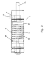
- the positioner of Fig. 2 may afford incremental travel from 0-0.5" from discrete position 1 and 0.5-1" from discrete position 2.
- the front and rear pistons are preferably not connected, but may be each connected to a shaft (e.g., a 1 ⁇ 2" shaft) that protrudes through a steel rod seal out of the rear end cap (the left of the cylinder as shown), where a forward stop (e.g., a bolt and washer) for the second piston may be fastened.
- a forward stop e.g., a bolt and washer
- To the right of the second piston may be a guide that prevents spring buckling and acts as a stop to prevent the spring from over-compressing.
- Regulated air may be fed to the front of the front cylinder, thereby achieving an incremental position as desired, or forcing the leftmost piston (the rear piston) to its leftmost discrete position (to force the leftmost piston to the rightmost discrete position, air of sufficient pressure to overcome the spring force may be fed into the left of the left piston); pressurized air may be fed to the rear of the rear cylinder, where such pressurized air may be used to change from one discrete position to the other (elimination of that pressure sufficient to keep the rear piston in the forward discrete position would, because of the spring's force, cause retraction of the rearward piston towards the rear of the cylinder).
- the spring may be attached to the rear piston. Specifications for one of many springs that may find application in the positioner of Fig. 2 are shown in Fig. 5 . It is also of note that certain embodiments of the inventive technology may involve apparatus disclosed in US Pat. App. Pub. No. US/2009/0288725 , hereby incorporated herein in its entirety.
- certain embodiments of the inventive technology achieve one or more of their advantages (particularly the advantage relative to enhanced resolution) by using the same spring, control air or regulated air to control incremental motion for more than one discrete position.
- one end of the spring i.e., the spring that provides the predictable bias force against the pressurized piston
- such end may now be moved (such movement occurring when a different discrete positioning is desired to achieve a different incremental positioning that is not achievable from the current discrete (indexed) position).
- Movement of such end now enables the resolution of such spring to be afforded to a new motion range based on that new discrete position (e.g., where with position 2, having a discrete, indexed “base” position of 0.5", the range of incremental positions may be limited to 0.5" to 1.0"; with position 3, having a discrete, indexed “base” position of 1.0", the range of incremental positions may be limited to 1.0" to 1.5"). Within each range, the spring's resolution would apply because it is shifted to the new discrete, indexed position.
- the new approach has a greater resolution, providing the ability to achieve much more accurate control and positions (e.g., 0.3675", or every 0.005" as desired) that were unachievable with conventional single spring apparatus (which perhaps could- achieve 0.367" or 0.368" at best, or every 0.01 as desired).
- Advantages may include the achievement of three or more different discrete positions without the need for an additional input control air for each additional position (of course, associated with each such additional input control air is additional valve(s), air line(s), wires, regulator(s) and/or microprocessor control componentry). Indeed, proper selection of the springs and adjustment of input pressures of the various embodiments can achieve three or more discrete positions.
- the inventive technology in particular embodiments, may be generally described as a positioner (e.g., a multipositioner) in which, in addition to providing the ability to position to discrete positions (as found in conventional multiposition cylinders), provides incremental positional control (at a higher resolution than characteristic of the movement from discrete position to another) between such discrete positions (perhaps affording infinite positional control).
- a positioner e.g., a multipositioner
- provides incremental positional control at a higher resolution than characteristic of the movement from discrete position to another
- positional control preferably discrete multiposition and incremental control, although certainly even only discrete multiposition control
- the number of discrete positions is three or greater, with only two pressurized fluid (e.g., pneumatic) inputs (a first input (e.g., a control input) may only affect achievement of discrete multipositions, not incremental control, while a second input (e.g., a regulated input) may be used only to achieve incremental control).
- a first input e.g., a control input
- a second input e.g., a regulated input
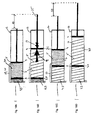
- Fig. 3 shows an embodiment in which pressurized fluid input at the left of the cylinder is used to move the first movable component (first piston in this embodiment) from one discrete stationary position to another, and fluid input at the right of the cylinder is used to move the second movable component (second piston in this embodiment) right or left at the higher resolution.
- the fluid input (effected by the second movable component force applier) at the right may also be useful to force the first piston all the way to the left (in its left most discrete stationary position), particularly when the compressed fluid input at the left is open to atmospheric pressure.
- the second piston may identically move with the first piston.
- the second piston can be moved at a higher resolution (than the resolution characteristic of the two or more discrete stationary positions) upon the addition of pressurized fluid at the right inlet of the cylinder.
- pressurized fluid at a pressure that is greater than the pressure of the fluid input at the right fluid inlet is input at the left fluid inlet, thereby moving the first piston.
- the postion of the left piston is locked, it must be unlocked first.
- the first piston can be retained there (e.g., by an appropriately high pressure at the left of the first piston and a stop, or locked, in other embodiments). Then, pressurized fluid input at the right can be adjusted as necessary to move the second piston incrementally, at the higher resolution (without moving the first piston).
- pressurized fluid input at the right can be adjusted as necessary to move the second piston incrementally, at the higher resolution (without moving the first piston).
- Other embodiments may operate in somewhat analogous manner.
- a positioner apparatus 1 that includes: a cylinder 1; a first movable component 3 and a second movable component 4 (e.g., a second piston or a cylinder end portion) established in the cylinder; an elastic element 5 (a spring, such as a helical spring 7, or a control volume 8 of fluid, as but a few examples) established within the cylinder so as to effect an elastic force 9 (e.g., a force whose strength varies with displacement of the elastic element, such displacement lengthening or shortening the elastic element) against the second movable component; a securable position adjustment mechanism 10 configured to selectively secure (e.g., as necessary to achieve positioner position as desired) the first movable component in at least two discrete first movable component positions 11 within the cylinder at a first movable component movement resolution; a second movable component force applier 12 configured to apply a second movable component force 13 that acts against the elastic force so as to move the second
- an elastic force 9 e.g.
- a force is said to act against a piston (or component) where that force acts against motion even in only one direction.
- the first movable component and the second movable component are each movable, relative to either the cylinder and/or the other component.
- the first movable component may be a movable first movable component and the second movable component may be a movable second movable component.
- At least one embodiment of the inventive technology may be described as a positioner apparatus that includes: a cylinder; a first movable component and a second movable component established in the cylinder; a securable position adjustment mechanism configured to selectively secure the first movable component in at least two discrete first movable component positions within the cylinder at a first movable component movement resolution; an elastic element established within the cylinder so as to effect an elastic force against the second movable component; a second movable component force applier configured to apply a second movable component force that acts against the elastic force so as to move the second movable component at a second movable component movement resolution; and a positioner that is positionally responsive to the second movable component, wherein, when the first movable component is secured in any one of the at least two discrete first movable component positions, the second movable component is movable both towards the first movable component and away from the first movable component (not simultaneously, of course).
- At least one embodiment of the inventive technology may be described as a positioner apparatus that includes: a cylinder; a first movable component and a second movable component established in the cylinder; an elastic element established within the cylinder so as to effect an elastic force against the second movable component; a securable position adjustment mechanism configured to selectively secure the first movable component in at least two discrete first movable component positions within the cylinder at a first movable component movement resolution; a second movable component force applier configured to apply a second movable component force that acts against the elastic force so as to move the second movable component at a second movable component movement resolution; and a positioner that is positionally responsive to the second movable component, wherein movement of the first movable component to the at least two discrete first movable component positions 11 effects movement of the positioner to at least two corresponding discrete positioner positions 15, and wherein the positioner is movable to intermediate positions 16 between any two proximate positioner positions 40 of the at least two
- the second movable component force applier (which applies force to the second movable component) may also be configured to apply a first movable component force that moves the first movable component from one of the at least two discrete first movable component positions to another (e.g., at the first movable component movement resolution) (see, e.g., Fig. 3 ).
- a first movable component force applier can be distinct from the second movable component force applier (see, e.g., Fig.
- the securable position adjustment mechanism also acts to impart a force that moves the first movable component (the cylinder end portion, in this embodiment)) and can apply the force that acts on the first movable component to move the first movable component from one of the at least two discrete first movable component positions to another at the first movable component movement resolution.
- the more efficient, robust design may be the design where the second movable component force applier may also be configured to apply a first movable component force 16 that moves the first movable component from one of the at least two discrete first movable component positions to another at the first movable component movement resolution (a spring, e.g. (a light spring might be preferable), might be used to counteract such force).
- a spring e.g. (a light spring might be preferable
- the design where there are distinct first movable component and second movable component force appliers is also viable. It is of note that the second piston force applier may act through the elastic element to apply the first movable component force.
- the first movable component may be a piston (a first piston 20), while in other embodiments, the first movable component may be something other than a piston (e.g., in the telescoping design of Fig. 9 ).
- it may be a portion (such as the inner portion) of the end of the cylinder (e.g., a telescoping cylinder).
- cylinder end portion 22 is considered within or in the cylinder (because that portion of the end of the cylinder that is in or within the cylinder is defined as a cylinder end portion).
- the second movable component may be a piston (a second piston 21), or, e.g., a cylinder end portion (e.g., in telescoping cylinder designs).
- both the first movable component and the second movable component are pistons.
- the elastic element has two ends 77, 78 (one that is closer to one end of the cylinder and another that is closer to a different end of the cylinder) that are translationally movable along a length of the cylinder (perhaps simultaneously, as may be seen when the first movable component is moved from one discrete stationary position to another).
- piston is generally defined as anything that is movable (e.g., slidably) within a cylinder along the length axis thereof; pistons need not necessarily contact inner walls of the cylinder (although in certain preferred embodiments they do).
- cylinder as used herein includes any structure having an outer surface and inner surface, the inner surface defining an inner space. It need not have a circular shape in cross-section.
- the elastic element may include a helical spring 30 and/or a control volume 31 of air or other gas (other possibilities include any substance with a elastic response (e.g., a consistent elastic response, such as one following Hooke's law)).
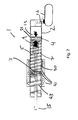
- the elastic element may be established between the first movable component and the second movable component (see, e.g., Figs. 2 , 3 and 7 ). It is of note that often, where an elastic element is other than a control volume of fluid (e.g., a captured volume of air), a vent is supplied in order that the elastic element act as intended.
- springs 30 or control volume 31 of fluid used in any of the inventive apparatus or methods herein may be as disclosed in, and may interact with an associated piston, as disclosed in US Pat. App. Pub. No. US/2009/0288725 .
- such reference while explanatory as to certain embodiments, does not limit possible designs that are otherwise covered by the claims from the scope of the inventive technology.
- the second movable component force applier itself is a conventional type of pneumatic force applier 32 (including, e.g., a pneumatic source of pressurized air, and a control system to control the pressure applied (such system perhaps including a valve and/or a regulator)).
- the same pneumatic force applier effects movement of the first movable component from one of the at least two discrete first movable component positions to another (see, e.g., Fig. 7 , where the pneumatic force applier moves the first movable component to the left, and where a light spring 43 may cause movement of the first movable component towards the right).
- the same pneumatic force applier may effect movement of the first movable component to at least three discrete first movable component positions (of course, at least three discrete first movable component positions are possible for other designs (e.g., those including a distinct first movable component and second movable component force appliers).
- the second movable component when the first movable component is secured in any one of the at least two discrete first movable component positions, the second movable component is movable both towards the first movable component and away from the first movable component.
- Such may allow for the precise control of the position of the positioner that is desired at times.
- a sufficiently high spring constant allows for precise control; a movable first movable component that can be secured against movement in any of two or more discrete stationary positions allows for greater total range of motion of the positioner at the higher resolution.
- movement of the first movable component to the at least two discrete first movable component positions effects movement of the positioner to at least two corresponding discrete positioner positions (see, e.g., Figs. 3 and 7 ).
- the positioner may be movable to intermediate positions between any two proximate positioner positions of the at least two corresponding discrete positioner positions.
- the first and second movable components are the only pistons established in the cylinder. Such may be a main reason for the robustness of particular embodiments.
- the securable position adjustment mechanism is a position adjustment mechanism (whether mechanical, electrical or both, as but a few examples) that enables the desired position of the part that it acts on (e.g., the first movable component) to be secured (e.g., locked, or retained in some fashion) via, e.g., a retainer mechanism 41 such that movement of the other piston (e.g., the second movable component) will not effect movement of the part the securable position adjustment mechanism acts on (e.g., the first movable component). It may, and preferably is, also releasable so that the retained position can be changed to a new retained position as desired or necessary.
- the retainer mechanism can be obstacle and spring, obstacle and controlled source of pneumatic force (perhaps with a spring), ratchet system, as but a few examples.
- the securable position adjustment mechanism may include a first movable component force applier that is distinct from the second movable component force applier and that applies a first movable component force that moves the first movable component from one of the at least two discrete first movable component positions to another at the first movable component movement resolution (see, e.g., Fig. 9 ).
- first movable component force applier may be a pneumatic force applier (as but one example; fluids other than compressed air (e.g., water or hydraulic fluid), can be used).
- a pneumatic force applier e.g., including a small pneumatic cylinder is a type of mechanical force applier.
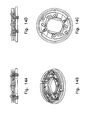
- the securable position adjustment mechanism may include a mechanical securable position adjustment mechanism 42, for example a spring and dedicated force applier mechanism (which, e.g., could be pneumatic), at least two first movable component movement obstacles (see, e.g., Fig. 3 ), a shuttle mechanism (see, e.g., Fig. 7 ), and/or a ratchet mechanism (see, e.g., Fig. 13 ).
- the securable position adjustment mechanism may include an electrical securable position adjustment mechanism (e.g., with an electric lock).
- the securable position adjustment mechanism may even include a spring 43 or control volume 44 established behind the first movable component, in certain embodiments (particularly those where the second movable component force applier is also the first movable component force applier); this spring may act to enable a force on the first movable component to move it from a first discrete "base" position to a second discrete "base” position.
- the second movable component may move with a greater resolution so as to provide the precise motion control desired. Moving the first movable component so as to change its secured position effects a larger range over which the positioner may move at its greater resolution.
- the second movable component movement resolution is greater than the first movable component movement resolution.
- Resolution as used herein is inversely related to the distance between the different available positions for the referenced device or within the referenced range (it may be viewed as being directly related to the "closeness" of such positions; the closer they are, the higher or greater the resolution).
- a first movable component is movable to three different positions of 0", 1 ⁇ 2" and 1
- a second movable component is movable to 30 different positions of 0", 0.033", 0.066", 0.099", etc.
- the second movable component is said to have a greater resolution than that of the first movable component (i.e., the average distance between its possible positions is, in value, smaller than the average distance between the possible positions of the first movable component).
- This usage is consistent with conventional usage of the term resolution found in the industry.
- a range is, e.g., from 0 to 1.0
- the possible positions within such range have an average distance between them of 1 ⁇ 4"
- the positioner moves identically with the second movable component, the positioner extends outside of the cylinder, the positioner is a rod, and/or the positioner slidingly passes through the first movable component (see, e.g., Fig. 6 ).
- first movable component is between the end of the positioner (whose position is of most concern) and the second movable component.
- second movable component force applier applies a force on the side of the second movable component that is opposite the side of the piston that the elastic force acts on.
- the positioner is identically positionally responsive to the second movable component (such that, e.g., 0.2" of movement of the piston effects 0.2" of movement of the positioner).
- the positioner may also be identically positionally responsive to the first movable component as well.
- the first movable component when the first movable component is moved, the second movable component moves as well.
- the first movable component will move only when the first movable component is not secured in one of its at least two discrete first movable component positions.
- Certain of the inventive method embodiments may be described as a positioner method comprising the steps of: establishing a first movable component and a second movable component in cylinder; establishing an elastic element in the cylinder so as to effect an elastic force against the second movable component; configuring a securable position adjustment mechanism to selectively secure the first movable component in at least two discrete first movable component positions within the cylinder at a first movable component movement resolution; configuring a second movable component force applier to apply a second movable component force that acts against the elastic force so as to move the second movable component at a second movable component movement resolution; and establishing a positioner to be positionally responsive to the second movable component, wherein the second movable component movement resolution is greater than the first movable component movement resolution. Certain steps of establishing and configuring as used herein may be accomplished, e.g., during manufacture of the apparatus or perhaps during installation.
- Certain inventive method embodiments may be described as a positioner method comprising the steps of: establishing a first movable component and a second movable component in a cylinder; configuring a securable position adjustment mechanism to selectively secure)as necessary for proper positioner position) the first movable component in at least two discrete first movable component positions within the cylinder at a first movable component movement resolution; establishing an elastic element within the cylinder so as to effect an elastic force against the second movable component; configuring a second movable component force applier to apply a second movable component force that acts against the elastic force so as to move the second movable component at a second movable component movement resolution; and establishing a positioner to be positionally responsive to the second movable component, wherein, when the first movable component is secured in any one of the at least two discrete first movable component positions, the second movable component is movable both towards the first movable component and away from the first movable component.
- the step of establishing a first moving component and a second moving component in a cylinder may include the step of establishing no other moving components (e.g., no other pistons) in the cylinder.
- the step of establishing an elastic element in the cylinder may comprise the step of establishing an elastic element that has two ends that are each translationally movable along a length of the cylinder (when the cylinder itself is stationary).
- Particular embodiments may further comprise the step of configuring the second movable component force applier (e.g., during manufacture and/or installation) to apply a first movable component force that moves the first movable component from one of the at least two discrete first movable component positions to another at the first movable component movement resolution.
- the step of configuring the second movable component force applier may comprise the step of configuring a pneumatic force applier.
- the step of configuring a securable position adjustment mechanism comprises the step of configuring a first movable component force applier that is distinct from the second movable component force applier, to apply a first movable component force that moves the first movable component from one of the at least two discrete first movable component positions to another at the first movable component movement resolution.
- the step of establishing an elastic element comprises the step of establishing a helical spring, establishing a control volume of air (or other gas), or indeed establishing any substance (whether fluid, solid or gaseous) or device that, preferably, has an elastic deformation response to a force acting on it (whether it behaves according to Hooke's Law (i.e., linearly), or otherwise).
- the step of establishing an elastic element may comprise the step of establishing an elastic element between the first movable component and the second movable component (or, instead on either side, where a central rod (e.g. a positioner rod), passes through the first movable component).
- the step of configuring a securable position adjustment mechanism may comprise the step of configuring a mechanical securable position adjustment mechanism.
- Such step itself may comprise the step of configuring a spring and dedicated force applier mechanism; such step may include the step of configuring at least two first movable component movement obstacles, a shuttle mechanism, or a ratchet mechanism (as but a few of many possibilities).
- the step of configuring a securable position adjustment mechanism may comprise the step of configuring an electrical securable position adjustment mechanism.
- the step of establishing a positioner may comprise one or more of the steps of: establishing a positioner that moves identically with the second movable component; establishing a positioner that extends outside of the cylinder; establishing a positioner rod; and establishing a positioner that slidingly passes through the first movable component.
- a positioning method that comprises the steps of: establishing in a first stationary position (e.g., one of the at least two discrete first movable component positions) a first movable component that is within a cylinder; then, while the first movable component is in the first stationary position, controllably moving a second movable component so as to achieve proper position of a positioner within a first operational run positional range 50 and with a positioner movement resolution, the positioner positionally responsive to the second movable component; conducting a first operational run with the first movable component in the first stationary position and the positioner positionally within the first run positional range; then, moving the first movable component to a second stationary position (e.g., a different one of the at least two discrete first movable component positions); then, while the first movable component is in the second stationary position, controllably moving the second movable component so as to achieve proper position of the positioner within a second operational run positional range 52 with the
- Such may be a type of alternating movement of the first and second movable components, where run preparation (whether from startup, shutdown, or for, e.g., a different bottle size in a bottle processing operation) may require alternating movement from the first movable component to the second movable component (e.g., where the first movable component is in proper position such that the second movable component can be controllably moved to achieve the desired positioning of the positioner, whether at a first, startup run, or for a second, different run), or from the second movable component to the first movable component (e.g., after an operation run is complete, for example, during operational shutdown, or in order to prepare for a different run having a different positioner position range requirement).
- Such steps of establishing are typically performed during operation of the apparatus, after installation of the manufactured apparatus; they may be done via manual or, preferably, computer control (e.g., where a microprocessor, perhaps from commands from user (or from feedback control, as particularly relates to movement of the second movable component).
- computer control e.g., where a microprocessor, perhaps from commands from user (or from feedback control, as particularly relates to movement of the second movable component).
- the step of conducting a first operational run may be performed during operational processing (e.g., bottle processing) that requires the postitioner be in a first operational run positioner range (e.g., from 1.2"-1.3") in order that processing be achieved as appropriate (e.g., bottles are controllably conveyed damage free and fed into processing stations such that such stations can process the bottles as intended). It is of note that bottle processing is not the only application of the inventive technology.
- the step of conducting a first operational run may be performed while performing the step of controllably moving a second movable component (such would be found as where a feedback system assures, at appropriate time intervals) so as to achieve proper positioning of the positioner within a first operational run positioner range. Such would typically involve a repetitive check positioner position and update positioner position as would be afforded by a feedback system, as discussed herein.
- the step of controllably moving a second movable component may comprise the step of acting against an elastic force (e.g., one applied by a helical spring (a helical spring force), by a control volume, or other type of elastic element).
- an elastic force e.g., one applied by a helical spring (a helical spring force), by a control volume, or other type of elastic element.
- the first stationary position and the second stationary position together exhibit a first movable component movement resolution, and the first movable component movement resolution may be less than the positioner movement resolution.
- the second operational run positional range has the positioner movement resolution. It is of further note that in particular embodiments, the step of moving the first movable component to a second stationary position comprises the step oftranslationally (e.g., from left to right or right to left if the cylinder is in a horizontal orientation) moving both ends of the elastic element in the same-direction.
- the step of controllably moving the second movable component comprises the step of pneumatically moving the second movable component
- the step of moving the first movable component may comprise the step of pneumatically moving the first movable component
- certain embodiments may utilize an electronic eye or other type of position sensor in a feedback system that automatically adjusts pneumatic pressure in order to change position of a piston as necessary, particularly where such piston effects a direct change in position of the positioner.
- a feedback system could be used to assure that the positioner was within 1 mm of a certain desired position; deviations therefrom could be detected by a position sensor and, perhaps through simple microprocessor control, substantially eliminated (to an acceptable degree) by appropriate increases or reductions in pneumatic pressure.
- Such a system would typically be used at the second movable component (which typically has a higher, or greater, resolution than that of the first movable component).
- At least one embodiment of the inventive technology may be described as a positioner apparatus that comprises: a cylinder; a first movable component and a second movable component established in the cylinder; an elastic element established within the cylinder so as to effect an elastic force against the second movable component; a securable position adjustment mechanism configured to selectively secure the first movable component in at least two discrete first movable component positions within the cylinder at a first movable component movement resolution; a second movable component force applier configured to apply a second movable component force that acts against the elastic force so as to move the second movable component at a second movable component movement resolution; and a positioner that is positionally responsive to the second movable component,wherein the elastic element has two ends (one that is closer to a first end of the cylinder and the other that is closer to a second end of the cylinder) that are-each translationally movable along a length of the cylinder.
- the second movable component movement resolution may be greater than the first movable component movement resolution; when the first movable component is secured in any one of the at least two discrete first movable component positions, the second movable component may be movable both towards the first movable component and away from the first movable component; and/or the positioner may be movable to intermediate positions between any two proximate positioner positions of the at least two corresponding discrete positioner positions.
- At least one embodiment of the inventive technology may be described as a positioner method that comprises the steps of: establishing a first movable component and a second movable component in cylinder; establishing an elastic element in the cylinder so as to effect an elastic force against the second movable component; configuring a securable position adjustment mechanism to selectively secure the first movable component in at least two discrete first movable component positions within the cylinder at a first movable component movement resolution; configuring a second movable component force applier to apply a second movable component force that acts against the elastic force so as to move the second movable component at a second movable component movement resolution; and establishing a positioner to be positionally responsive to the second movable component, wherein the step of establishing an elastic element in the cylinder comprises the step of establishing an elastic element that has two ends that are each translationally movable (often simultaneously) along a length of the cylinder.
- the second movable component movement resolution may be greater than the first movable component movement resolution; when the first movable component is secured in any one of the at least two discrete first movable component positions, the second movable component is movable both towards the first movable component and away from the first movable component; and/or the positioner is movable to intermediate positions between any two proximate positioner positions of the at least two corresponding discrete positioner positions.
- the present invention includes a variety of aspects, which may be combined in different ways.
- the following descriptions are provided to list elements and describe some of the embodiments of the present invention. These elements are listed with initial embodiments, however it should be understood that they may be combined in any manner and in any number to create additional embodiments.
- the variously described examples and preferred embodiments should not be construed to limit the present invention to only the explicitly described systems, techniques, and applications. Further, this description should be understood to support and encompass descriptions and claims of all the various embodiments, systems, techniques, methods, devices, and applications with any number of the disclosed elements, with each element alone, and also with any and all various permutations and combinations of all elements in this or any subsequent application.
- the basic concepts of the present invention may be embodied in a variety of ways. It involves both positioning techniques as well as devices to accomplish the appropriate position. In this application, the positioning techniques are disclosed as part of the results shown to be achieved by the various devices described and as steps which are inherent to utilization. They are simply the natural result of utilizing the devices as intended and described. In addition, while some devices are disclosed, it should be understood that these not only accomplish certain methods but also can be varied in a number of ways. Importantly, as to all of the foregoing, all of these facets should be understood to be encompassed by this disclosure.
- each of the various elements of the invention and claims may also be achieved in a variety of manners.
- an element is to be understood as encompassing individual as well as plural structures that may or may not be physically connected.
- This disclosure should be understood to encompass each such variation, be it a variation of an embodiment of any apparatus embodiment, a method or process embodiment, or even merely a variation of any element of these.
- the words for each element may be expressed by equivalent apparatus terms or method termseven if only the function or result is the same. Such equivalent, broader, or even more generic terms should be considered to be encompassed in the description of each element or action.
- each of the multipositioner devices as herein disclosed and described, ii) the related methods disclosed and described, iii) similar, equivalent, and even implicit variations of each of these devices and methods, iv) those alternative designs which accomplish each of the functions shown as are disclosed and described, v) those alternative designs and methods which accomplish each of the functions shown as are implicit to accomplish that which is disclosed and described, vi) each feature, component, and step shown as separate and independent inventions, vii) the applications enhanced by the various systems or components disclosed, viii) the resulting products produced by such systems or components, ix) each system, method, and element shown or described as now applied to any specific field or devices mentioned, x) methods and apparatuses substantially as described hereinbefore and with reference to any of the accompanying examples, xi) the various combinations and permutations of each of the elements disclosed, xii) each potentially dependent claim or concept as a dependency on each and every one
- any claims set forth at any time are hereby incorporated by reference as part of this description of the invention, and the applicant expressly reserves the right to use all of or a portion of such incorporated content of such claims as additional description to support any of or all of the claims or any element or component thereof, and the applicant further expressly reserves the right to move any portion of or all of the incorporated content of such claims or any element or component thereof from the description into the claims or vice-versa as necessary to define the matter for which protection is sought by this application or by any subsequent continuation, division, or continuation-in-part application thereof, or to obtain any benefit of, reduction in fees pursuant to, or to comply with the patent laws, rules, or regulations of any country or treaty, and such content incorporated by reference shall survive during the entire pendency of this application including any subsequent continuation, division, or continuation-in-part application thereof or any reissue or extension thereon.
Landscapes
- Engineering & Computer Science (AREA)
- Physics & Mathematics (AREA)
- Fluid Mechanics (AREA)
- Mechanical Engineering (AREA)
- General Engineering & Computer Science (AREA)
- Actuator (AREA)
- Jigs For Machine Tools (AREA)
- Lining And Supports For Tunnels (AREA)
- Control Of Position Or Direction (AREA)
Applications Claiming Priority (1)
| Application Number | Priority Date | Filing Date | Title |
|---|---|---|---|
| US26325509P | 2009-11-20 | 2009-11-20 |
Publications (3)
| Publication Number | Publication Date |
|---|---|
| EP2325501A2 true EP2325501A2 (fr) | 2011-05-25 |
| EP2325501A3 EP2325501A3 (fr) | 2014-02-26 |
| EP2325501B1 EP2325501B1 (fr) | 2018-08-08 |
Family
ID=43608086
Family Applications (1)
| Application Number | Title | Priority Date | Filing Date |
|---|---|---|---|
| EP10014842.8A Active EP2325501B1 (fr) | 2009-11-20 | 2010-11-22 | Cylindre de positionnement et procédés |
Country Status (3)
| Country | Link |
|---|---|
| US (1) | US8707851B2 (fr) |
| EP (1) | EP2325501B1 (fr) |
| ES (1) | ES2686250T3 (fr) |
Cited By (2)
| Publication number | Priority date | Publication date | Assignee | Title |
|---|---|---|---|---|
| CN103410807A (zh) * | 2013-09-02 | 2013-11-27 | 缪乾 | 可调行程多位置气缸 |
| CN103615428A (zh) * | 2013-12-03 | 2014-03-05 | 三一汽车制造有限公司 | 液压油缸及泵送机构及稠浆物料泵 |
Families Citing this family (7)
| Publication number | Priority date | Publication date | Assignee | Title |
|---|---|---|---|---|
| EP2503188B1 (fr) * | 2011-03-25 | 2015-01-21 | NAF Neunkirchener Achsenfabrik AG | Cylindre de commutation pour un dispositif d'entraînement, notamment pour un engin automobile, dispositif d'entraînement, machine de travail et son procédé de fonctionnement dans ledit engin. |
| EP2692235B1 (fr) * | 2012-08-03 | 2017-10-11 | Poly-clip System GmbH & Co. KG | Dispositif d'entraînement de module de fermeture par clip et procédé pour déplacer un module de fermeture par clip |
| CN104373412B (zh) * | 2014-09-29 | 2016-11-30 | 宁波亨博电磁技术有限公司 | 一种双击气缸 |
| CN106926028A (zh) * | 2015-12-29 | 2017-07-07 | 武汉重型机床集团有限公司 | 一种减压夹紧结构 |
| CN106352151B (zh) * | 2016-11-25 | 2019-04-02 | 兰州高压阀门有限公司 | 气缸内液压缓冲杆支撑结构 |
| WO2019113829A1 (fr) * | 2017-12-13 | 2019-06-20 | 深圳市凯卓立液压设备股份有限公司 | Cylindre à huile composite intégrant la fonction d'un cylindre d'équilibrage et système hydraulique utilisant le cylindre à huile |
| US12055161B2 (en) | 2019-10-23 | 2024-08-06 | Asco, L. P. | Valve manifold, valve and actuator assembly |
Citations (1)
| Publication number | Priority date | Publication date | Assignee | Title |
|---|---|---|---|---|
| US20090288725A1 (en) | 2008-05-20 | 2009-11-26 | Advanced Manufacturing Technology For Bottles, Inc | Position Control Apparatus and Methods |
Family Cites Families (25)
| Publication number | Priority date | Publication date | Assignee | Title |
|---|---|---|---|---|
| US1475508A (en) * | 1921-08-16 | 1923-11-27 | Esnault-Pelterie Robert | Means for regulating the output of pumps operated by the engines of automobiles or the like |
| US2095820A (en) | 1934-08-23 | 1937-10-12 | Gen Electric | Control mechanism for multiple hydraulic gears |
| US2484603A (en) | 1944-07-11 | 1949-10-11 | Olaer Patent Co | Hydraulic control device |
| DE1964084U (de) * | 1967-04-14 | 1967-07-13 | Maschb Fischer & Mueller | Zweikammer-pressluftzylinder. |
| US5237906A (en) | 1991-10-25 | 1993-08-24 | Raymond Robert E | Linear fluid power actuator assembly |
| US5211280A (en) | 1992-03-13 | 1993-05-18 | Storcan Limitee | Adjustable guide rail apparatus for independently adjusting positions of first and second guide rails disposed respectively on opposite sides of the path of a conveyor |
| JPH0914205A (ja) | 1995-06-28 | 1997-01-14 | Ii P Le-Mu:Kk | デジタル的流体圧制御装置 |
| US6000884A (en) | 1997-03-27 | 1999-12-14 | Advanced Manufacturing Technology | Apparatus for controlling flow in air conveyor systems |
| SE516025C2 (sv) | 1999-05-04 | 2001-11-12 | Besam Ab | Manövreringsanordning för dörrar, grindar och dylika element |
| US6241072B1 (en) | 1999-05-24 | 2001-06-05 | Advanced Manufacturing Technology | Bottle manufacturing hopper system |
| US6196788B1 (en) | 1999-11-09 | 2001-03-06 | Advanced Manufacturing Technology | Container handling device and method |
| US6408740B1 (en) * | 2000-12-04 | 2002-06-25 | Welker Bearing Company | Three position cylinder |
| WO2002045982A1 (fr) | 2000-12-07 | 2002-06-13 | Visteon Global Technologies, Inc. | Systeme de suspension pour vehicule |
| US6389341B1 (en) | 2001-01-12 | 2002-05-14 | Davis Family Irrevocable Trust | Control system for a vehicle suspension |
| US6589008B1 (en) | 2001-10-02 | 2003-07-08 | Advanced Manufacturing Technology | Container handling device and method |
| WO2004074146A1 (fr) | 2003-02-18 | 2004-09-02 | Sidel (Canada) Inc. | Ensemble d'actionnement pour trajet de guidage a largeur reglable dans un systeme de convoyeur pour bouteilles |
| US7085636B2 (en) | 2003-10-17 | 2006-08-01 | Visteon Global Technologies, Inc. | Transmissibility shaping control for active vehicle suspension systems |
| US7104180B2 (en) | 2003-11-04 | 2006-09-12 | Delphi Technologies, Inc. | Low noise linear actuator |
| DE102004013662B4 (de) | 2004-03-19 | 2006-01-26 | Lucas Automotive Gmbh | Hauptbremszylinder mit integrierter Transportsicherung |
| US20070095247A1 (en) | 2005-02-03 | 2007-05-03 | Advanced Manufacturing Technology | Guide positioning system for a container transport line |
| US7210572B2 (en) | 2005-02-03 | 2007-05-01 | Advanced Manufacturing Technology | Adjustable guide for a bottle handling system |
| DE102005011659A1 (de) | 2005-03-08 | 2006-09-14 | Khs Ag | Betätigungselement sowie Füllmaschine mit derartigen Betätigungselementen |
| JP4525660B2 (ja) | 2006-10-13 | 2010-08-18 | トヨタ自動車株式会社 | 車両用サスペンションシステム |
| US7721876B2 (en) | 2006-10-27 | 2010-05-25 | Illinois Tool Works Inc. | Adjustable side rails for article conveying system, and conveyor and system incorporating same |
| US7530453B2 (en) | 2006-10-30 | 2009-05-12 | Advanced Manufacturing Technology | Adjustable neck guide |
-
2010
- 2010-11-19 US US12/950,736 patent/US8707851B2/en active Active
- 2010-11-22 ES ES10014842.8T patent/ES2686250T3/es active Active
- 2010-11-22 EP EP10014842.8A patent/EP2325501B1/fr active Active
Patent Citations (1)
| Publication number | Priority date | Publication date | Assignee | Title |
|---|---|---|---|---|
| US20090288725A1 (en) | 2008-05-20 | 2009-11-26 | Advanced Manufacturing Technology For Bottles, Inc | Position Control Apparatus and Methods |
Cited By (3)
| Publication number | Priority date | Publication date | Assignee | Title |
|---|---|---|---|---|
| CN103410807A (zh) * | 2013-09-02 | 2013-11-27 | 缪乾 | 可调行程多位置气缸 |
| CN103615428A (zh) * | 2013-12-03 | 2014-03-05 | 三一汽车制造有限公司 | 液压油缸及泵送机构及稠浆物料泵 |
| CN103615428B (zh) * | 2013-12-03 | 2016-02-10 | 三一汽车制造有限公司 | 液压油缸及泵送机构及稠浆物料泵 |
Also Published As
| Publication number | Publication date |
|---|---|
| ES2686250T3 (es) | 2018-10-17 |
| EP2325501B1 (fr) | 2018-08-08 |
| US20110120120A1 (en) | 2011-05-26 |
| US8707851B2 (en) | 2014-04-29 |
| EP2325501A3 (fr) | 2014-02-26 |
Similar Documents
| Publication | Publication Date | Title |
|---|---|---|
| EP2325501A2 (fr) | Cylindre de positionnement et procédés | |
| EP4394204A3 (fr) | Ressort à gaz avec décharge de pression de dépassement de course | |
| US6895749B2 (en) | Double-acting pressure intensifying cylinder and method for intensifying pressure in the cylinder | |
| US7779745B2 (en) | Automatic-locking hydraulic jack | |
| EP1498187A3 (fr) | Valve | |
| DE102013019499A1 (de) | Kolbenverdichter und Verfahren zum Verdichten eines tiefkalten, gasförmigen Mediums, insbesondere Wasserstoff | |
| US9121419B2 (en) | Hydraulic drive device having two pressure chambers and method for operating a hydraulic drive device having two pressure chambers | |
| CN204267423U (zh) | 伸缩式液压油缸 | |
| CN211623864U (zh) | 柱塞活塞复合双作用油缸 | |
| DE10246766B3 (de) | Endlagengedämpfter Pneumatikzylinder | |
| CN209800421U (zh) | 多级液压油缸 | |
| EP2223629A1 (fr) | Colonne télescopique | |
| CN209041200U (zh) | 一种液压无级变压系统 | |
| CN202391856U (zh) | 缸定位二级可调推力液压油缸装置 | |
| US3683752A (en) | Multiposition fluid-operable piston and cylinder unit | |
| CN110303368B (zh) | 一种超高精度液压微分机床给进系统 | |
| CN218320492U (zh) | 一种液压顶升气缸 | |
| DE60015181T2 (de) | Diamantförmiges fluidgelenk, system und motor | |
| CN218598895U (zh) | 一种调压阀 | |
| RU212251U1 (ru) | Устройство для пластического деформирования цилиндрических частей металлических изделий | |
| CN109590779A (zh) | 一种多段式压料机构 | |
| CN219176684U (zh) | 一种调节油缸行程的装置 | |
| ATE299054T1 (de) | Rohrbiegemaschine mit einem hydraulikkreislauf zur linearbewegung eines rollenschlittens | |
| WO2006062755A3 (fr) | Systeme de pompage haute pression a orifice de decharge ouvert | |
| CN104019078B (zh) | 短行程长活塞杆油缸压紧方法 |
Legal Events
| Date | Code | Title | Description |
|---|---|---|---|
| PUAI | Public reference made under article 153(3) epc to a published international application that has entered the european phase |
Free format text: ORIGINAL CODE: 0009012 |
|
| AK | Designated contracting states |
Kind code of ref document: A2 Designated state(s): AL AT BE BG CH CY CZ DE DK EE ES FI FR GB GR HR HU IE IS IT LI LT LU LV MC MK MT NL NO PL PT RO RS SE SI SK SM TR |
|
| AX | Request for extension of the european patent |
Extension state: BA ME |
|
| RAP1 | Party data changed (applicant data changed or rights of an application transferred) |
Owner name: FLEXIBILITY ENGINEERING, LLC |
|
| PUAL | Search report despatched |
Free format text: ORIGINAL CODE: 0009013 |
|
| AK | Designated contracting states |
Kind code of ref document: A3 Designated state(s): AL AT BE BG CH CY CZ DE DK EE ES FI FR GB GR HR HU IE IS IT LI LT LU LV MC MK MT NL NO PL PT RO RS SE SI SK SM TR |
|
| AX | Request for extension of the european patent |
Extension state: BA ME |
|
| RIC1 | Information provided on ipc code assigned before grant |
Ipc: F15B 15/24 20060101ALI20140117BHEP Ipc: F15B 15/14 20060101AFI20140117BHEP |
|
| 17P | Request for examination filed |
Effective date: 20140702 |
|
| RBV | Designated contracting states (corrected) |
Designated state(s): AL AT BE BG CH CY CZ DE DK EE ES FI FR GB GR HR HU IE IS IT LI LT LU LV MC MK MT NL NO PL PT RO RS SE SI SK SM TR |
|
| STAA | Information on the status of an ep patent application or granted ep patent |
Free format text: STATUS: EXAMINATION IS IN PROGRESS |
|
| 17Q | First examination report despatched |
Effective date: 20161024 |
|
| GRAP | Despatch of communication of intention to grant a patent |
Free format text: ORIGINAL CODE: EPIDOSNIGR1 |
|
| STAA | Information on the status of an ep patent application or granted ep patent |
Free format text: STATUS: GRANT OF PATENT IS INTENDED |
|
| INTG | Intention to grant announced |
Effective date: 20180226 |
|
| GRAJ | Information related to disapproval of communication of intention to grant by the applicant or resumption of examination proceedings by the epo deleted |
Free format text: ORIGINAL CODE: EPIDOSDIGR1 |
|
| STAA | Information on the status of an ep patent application or granted ep patent |
Free format text: STATUS: EXAMINATION IS IN PROGRESS |
|
| GRAR | Information related to intention to grant a patent recorded |
Free format text: ORIGINAL CODE: EPIDOSNIGR71 |
|
| GRAS | Grant fee paid |
Free format text: ORIGINAL CODE: EPIDOSNIGR3 |
|
| STAA | Information on the status of an ep patent application or granted ep patent |
Free format text: STATUS: GRANT OF PATENT IS INTENDED |
|
| GRAA | (expected) grant |
Free format text: ORIGINAL CODE: 0009210 |
|
| STAA | Information on the status of an ep patent application or granted ep patent |
Free format text: STATUS: THE PATENT HAS BEEN GRANTED |
|
| INTC | Intention to grant announced (deleted) | ||
| AK | Designated contracting states |
Kind code of ref document: B1 Designated state(s): AL AT BE BG CH CY CZ DE DK EE ES FI FR GB GR HR HU IE IS IT LI LT LU LV MC MK MT NL NO PL PT RO RS SE SI SK SM TR |
|
| INTG | Intention to grant announced |
Effective date: 20180629 |
|
| REG | Reference to a national code |
Ref country code: GB Ref legal event code: FG4D |
|
| REG | Reference to a national code |
Ref country code: CH Ref legal event code: EP Ref country code: AT Ref legal event code: REF Ref document number: 1027339 Country of ref document: AT Kind code of ref document: T Effective date: 20180815 |
|
| REG | Reference to a national code |
Ref country code: IE Ref legal event code: FG4D |
|
| REG | Reference to a national code |
Ref country code: DE Ref legal event code: R096 Ref document number: 602010052448 Country of ref document: DE |
|
| REG | Reference to a national code |
Ref country code: ES Ref legal event code: FG2A Ref document number: 2686250 Country of ref document: ES Kind code of ref document: T3 Effective date: 20181017 |
|
| REG | Reference to a national code |
Ref country code: NL Ref legal event code: MP Effective date: 20180808 |
|
| REG | Reference to a national code |
Ref country code: LT Ref legal event code: MG4D |
|
| REG | Reference to a national code |
Ref country code: AT Ref legal event code: MK05 Ref document number: 1027339 Country of ref document: AT Kind code of ref document: T Effective date: 20180808 |
|
| PG25 | Lapsed in a contracting state [announced via postgrant information from national office to epo] |
Ref country code: LT Free format text: LAPSE BECAUSE OF FAILURE TO SUBMIT A TRANSLATION OF THE DESCRIPTION OR TO PAY THE FEE WITHIN THE PRESCRIBED TIME-LIMIT Effective date: 20180808 Ref country code: PL Free format text: LAPSE BECAUSE OF FAILURE TO SUBMIT A TRANSLATION OF THE DESCRIPTION OR TO PAY THE FEE WITHIN THE PRESCRIBED TIME-LIMIT Effective date: 20180808 Ref country code: RS Free format text: LAPSE BECAUSE OF FAILURE TO SUBMIT A TRANSLATION OF THE DESCRIPTION OR TO PAY THE FEE WITHIN THE PRESCRIBED TIME-LIMIT Effective date: 20180808 Ref country code: NL Free format text: LAPSE BECAUSE OF FAILURE TO SUBMIT A TRANSLATION OF THE DESCRIPTION OR TO PAY THE FEE WITHIN THE PRESCRIBED TIME-LIMIT Effective date: 20180808 Ref country code: FI Free format text: LAPSE BECAUSE OF FAILURE TO SUBMIT A TRANSLATION OF THE DESCRIPTION OR TO PAY THE FEE WITHIN THE PRESCRIBED TIME-LIMIT Effective date: 20180808 Ref country code: NO Free format text: LAPSE BECAUSE OF FAILURE TO SUBMIT A TRANSLATION OF THE DESCRIPTION OR TO PAY THE FEE WITHIN THE PRESCRIBED TIME-LIMIT Effective date: 20181108 Ref country code: BG Free format text: LAPSE BECAUSE OF FAILURE TO SUBMIT A TRANSLATION OF THE DESCRIPTION OR TO PAY THE FEE WITHIN THE PRESCRIBED TIME-LIMIT Effective date: 20181108 Ref country code: GR Free format text: LAPSE BECAUSE OF FAILURE TO SUBMIT A TRANSLATION OF THE DESCRIPTION OR TO PAY THE FEE WITHIN THE PRESCRIBED TIME-LIMIT Effective date: 20181109 Ref country code: IS Free format text: LAPSE BECAUSE OF FAILURE TO SUBMIT A TRANSLATION OF THE DESCRIPTION OR TO PAY THE FEE WITHIN THE PRESCRIBED TIME-LIMIT Effective date: 20181208 Ref country code: AT Free format text: LAPSE BECAUSE OF FAILURE TO SUBMIT A TRANSLATION OF THE DESCRIPTION OR TO PAY THE FEE WITHIN THE PRESCRIBED TIME-LIMIT Effective date: 20180808 Ref country code: SE Free format text: LAPSE BECAUSE OF FAILURE TO SUBMIT A TRANSLATION OF THE DESCRIPTION OR TO PAY THE FEE WITHIN THE PRESCRIBED TIME-LIMIT Effective date: 20180808 |
|
| PG25 | Lapsed in a contracting state [announced via postgrant information from national office to epo] |
Ref country code: HR Free format text: LAPSE BECAUSE OF FAILURE TO SUBMIT A TRANSLATION OF THE DESCRIPTION OR TO PAY THE FEE WITHIN THE PRESCRIBED TIME-LIMIT Effective date: 20180808 Ref country code: LV Free format text: LAPSE BECAUSE OF FAILURE TO SUBMIT A TRANSLATION OF THE DESCRIPTION OR TO PAY THE FEE WITHIN THE PRESCRIBED TIME-LIMIT Effective date: 20180808 Ref country code: AL Free format text: LAPSE BECAUSE OF FAILURE TO SUBMIT A TRANSLATION OF THE DESCRIPTION OR TO PAY THE FEE WITHIN THE PRESCRIBED TIME-LIMIT Effective date: 20180808 |
|
| PG25 | Lapsed in a contracting state [announced via postgrant information from national office to epo] |
Ref country code: CZ Free format text: LAPSE BECAUSE OF FAILURE TO SUBMIT A TRANSLATION OF THE DESCRIPTION OR TO PAY THE FEE WITHIN THE PRESCRIBED TIME-LIMIT Effective date: 20180808 Ref country code: RO Free format text: LAPSE BECAUSE OF FAILURE TO SUBMIT A TRANSLATION OF THE DESCRIPTION OR TO PAY THE FEE WITHIN THE PRESCRIBED TIME-LIMIT Effective date: 20180808 Ref country code: EE Free format text: LAPSE BECAUSE OF FAILURE TO SUBMIT A TRANSLATION OF THE DESCRIPTION OR TO PAY THE FEE WITHIN THE PRESCRIBED TIME-LIMIT Effective date: 20180808 |
|
| REG | Reference to a national code |
Ref country code: DE Ref legal event code: R097 Ref document number: 602010052448 Country of ref document: DE |
|
| PG25 | Lapsed in a contracting state [announced via postgrant information from national office to epo] |
Ref country code: DK Free format text: LAPSE BECAUSE OF FAILURE TO SUBMIT A TRANSLATION OF THE DESCRIPTION OR TO PAY THE FEE WITHIN THE PRESCRIBED TIME-LIMIT Effective date: 20180808 Ref country code: SM Free format text: LAPSE BECAUSE OF FAILURE TO SUBMIT A TRANSLATION OF THE DESCRIPTION OR TO PAY THE FEE WITHIN THE PRESCRIBED TIME-LIMIT Effective date: 20180808 Ref country code: SK Free format text: LAPSE BECAUSE OF FAILURE TO SUBMIT A TRANSLATION OF THE DESCRIPTION OR TO PAY THE FEE WITHIN THE PRESCRIBED TIME-LIMIT Effective date: 20180808 |
|
| PLBE | No opposition filed within time limit |
Free format text: ORIGINAL CODE: 0009261 |
|
| STAA | Information on the status of an ep patent application or granted ep patent |
Free format text: STATUS: NO OPPOSITION FILED WITHIN TIME LIMIT |
|
| REG | Reference to a national code |
Ref country code: CH Ref legal event code: PL |
|
| 26N | No opposition filed |
Effective date: 20190509 |
|
| PG25 | Lapsed in a contracting state [announced via postgrant information from national office to epo] |
Ref country code: MC Free format text: LAPSE BECAUSE OF FAILURE TO SUBMIT A TRANSLATION OF THE DESCRIPTION OR TO PAY THE FEE WITHIN THE PRESCRIBED TIME-LIMIT Effective date: 20180808 Ref country code: LU Free format text: LAPSE BECAUSE OF NON-PAYMENT OF DUE FEES Effective date: 20181122 |
|
| REG | Reference to a national code |
Ref country code: BE Ref legal event code: MM Effective date: 20181130 |
|
| PG25 | Lapsed in a contracting state [announced via postgrant information from national office to epo] |
Ref country code: LI Free format text: LAPSE BECAUSE OF NON-PAYMENT OF DUE FEES Effective date: 20181130 Ref country code: SI Free format text: LAPSE BECAUSE OF FAILURE TO SUBMIT A TRANSLATION OF THE DESCRIPTION OR TO PAY THE FEE WITHIN THE PRESCRIBED TIME-LIMIT Effective date: 20180808 Ref country code: CH Free format text: LAPSE BECAUSE OF NON-PAYMENT OF DUE FEES Effective date: 20181130 |
|
| PG25 | Lapsed in a contracting state [announced via postgrant information from national office to epo] |
Ref country code: BE Free format text: LAPSE BECAUSE OF NON-PAYMENT OF DUE FEES Effective date: 20181130 |
|
| PG25 | Lapsed in a contracting state [announced via postgrant information from national office to epo] |
Ref country code: MT Free format text: LAPSE BECAUSE OF NON-PAYMENT OF DUE FEES Effective date: 20181122 |
|
| PG25 | Lapsed in a contracting state [announced via postgrant information from national office to epo] |
Ref country code: TR Free format text: LAPSE BECAUSE OF FAILURE TO SUBMIT A TRANSLATION OF THE DESCRIPTION OR TO PAY THE FEE WITHIN THE PRESCRIBED TIME-LIMIT Effective date: 20180808 |
|
| PG25 | Lapsed in a contracting state [announced via postgrant information from national office to epo] |
Ref country code: PT Free format text: LAPSE BECAUSE OF FAILURE TO SUBMIT A TRANSLATION OF THE DESCRIPTION OR TO PAY THE FEE WITHIN THE PRESCRIBED TIME-LIMIT Effective date: 20180808 |
|
| PG25 | Lapsed in a contracting state [announced via postgrant information from national office to epo] |
Ref country code: MK Free format text: LAPSE BECAUSE OF NON-PAYMENT OF DUE FEES Effective date: 20180808 Ref country code: CY Free format text: LAPSE BECAUSE OF FAILURE TO SUBMIT A TRANSLATION OF THE DESCRIPTION OR TO PAY THE FEE WITHIN THE PRESCRIBED TIME-LIMIT Effective date: 20180808 Ref country code: HU Free format text: LAPSE BECAUSE OF FAILURE TO SUBMIT A TRANSLATION OF THE DESCRIPTION OR TO PAY THE FEE WITHIN THE PRESCRIBED TIME-LIMIT; INVALID AB INITIO Effective date: 20101122 |
|
| P01 | Opt-out of the competence of the unified patent court (upc) registered |
Effective date: 20230601 |
|
| PGFP | Annual fee paid to national office [announced via postgrant information from national office to epo] |
Ref country code: DE Payment date: 20251128 Year of fee payment: 16 |
|
| PGFP | Annual fee paid to national office [announced via postgrant information from national office to epo] |
Ref country code: GB Payment date: 20251119 Year of fee payment: 16 |
|
| PGFP | Annual fee paid to national office [announced via postgrant information from national office to epo] |
Ref country code: IT Payment date: 20251121 Year of fee payment: 16 |
|
| PGFP | Annual fee paid to national office [announced via postgrant information from national office to epo] |
Ref country code: FR Payment date: 20251120 Year of fee payment: 16 |
|
| PGFP | Annual fee paid to national office [announced via postgrant information from national office to epo] |
Ref country code: IE Payment date: 20251121 Year of fee payment: 16 |
|
| PGFP | Annual fee paid to national office [announced via postgrant information from national office to epo] |
Ref country code: ES Payment date: 20251216 Year of fee payment: 16 |