EP2325548B1 - Hybridbeleuchtungsvorrichtung und -beleuchtungsverfahren - Google Patents
Hybridbeleuchtungsvorrichtung und -beleuchtungsverfahren Download PDFInfo
- Publication number
- EP2325548B1 EP2325548B1 EP10382301A EP10382301A EP2325548B1 EP 2325548 B1 EP2325548 B1 EP 2325548B1 EP 10382301 A EP10382301 A EP 10382301A EP 10382301 A EP10382301 A EP 10382301A EP 2325548 B1 EP2325548 B1 EP 2325548B1
- Authority
- EP
- European Patent Office
- Prior art keywords
- lighting device
- panel
- hybrid
- hybrid lighting
- guide
- Prior art date
- Legal status (The legal status is an assumption and is not a legal conclusion. Google has not performed a legal analysis and makes no representation as to the accuracy of the status listed.)
- Not-in-force
Links
Images


Classifications
-
- F—MECHANICAL ENGINEERING; LIGHTING; HEATING; WEAPONS; BLASTING
- F21—LIGHTING
- F21S—NON-PORTABLE LIGHTING DEVICES; SYSTEMS THEREOF; VEHICLE LIGHTING DEVICES SPECIALLY ADAPTED FOR VEHICLE EXTERIORS
- F21S11/00—Non-electric lighting devices or systems using daylight
-
- F—MECHANICAL ENGINEERING; LIGHTING; HEATING; WEAPONS; BLASTING
- F21—LIGHTING
- F21S—NON-PORTABLE LIGHTING DEVICES; SYSTEMS THEREOF; VEHICLE LIGHTING DEVICES SPECIALLY ADAPTED FOR VEHICLE EXTERIORS
- F21S19/00—Lighting devices or systems employing combinations of electric and non-electric light sources; Replacing or exchanging electric light sources with non-electric light sources or vice versa
- F21S19/005—Combining sunlight and electric light sources for indoor illumination
-
- F—MECHANICAL ENGINEERING; LIGHTING; HEATING; WEAPONS; BLASTING
- F21—LIGHTING
- F21S—NON-PORTABLE LIGHTING DEVICES; SYSTEMS THEREOF; VEHICLE LIGHTING DEVICES SPECIALLY ADAPTED FOR VEHICLE EXTERIORS
- F21S9/00—Lighting devices with a built-in power supply; Systems employing lighting devices with a built-in power supply
- F21S9/02—Lighting devices with a built-in power supply; Systems employing lighting devices with a built-in power supply the power supply being a battery or accumulator
- F21S9/03—Lighting devices with a built-in power supply; Systems employing lighting devices with a built-in power supply the power supply being a battery or accumulator rechargeable by exposure to light
- F21S9/037—Lighting devices with a built-in power supply; Systems employing lighting devices with a built-in power supply the power supply being a battery or accumulator rechargeable by exposure to light the solar unit and the lighting unit being located within or on the same housing
-
- F—MECHANICAL ENGINEERING; LIGHTING; HEATING; WEAPONS; BLASTING
- F21—LIGHTING
- F21V—FUNCTIONAL FEATURES OR DETAILS OF LIGHTING DEVICES OR SYSTEMS THEREOF; STRUCTURAL COMBINATIONS OF LIGHTING DEVICES WITH OTHER ARTICLES, NOT OTHERWISE PROVIDED FOR
- F21V33/00—Structural combinations of lighting devices with other articles, not otherwise provided for
- F21V33/006—General building constructions or finishing work for buildings, e.g. roofs, gutters, stairs or floors; Garden equipment; Sunshades or parasols
-
- G—PHYSICS
- G02—OPTICS
- G02B—OPTICAL ELEMENTS, SYSTEMS OR APPARATUS
- G02B6/00—Light guides; Structural details of arrangements comprising light guides and other optical elements, e.g. couplings
- G02B6/0001—Light guides; Structural details of arrangements comprising light guides and other optical elements, e.g. couplings specially adapted for lighting devices or systems
- G02B6/0005—Light guides; Structural details of arrangements comprising light guides and other optical elements, e.g. couplings specially adapted for lighting devices or systems the light guides being of the fibre type
- G02B6/0006—Coupling light into the fibre
-
- H—ELECTRICITY
- H10—SEMICONDUCTOR DEVICES; ELECTRIC SOLID-STATE DEVICES NOT OTHERWISE PROVIDED FOR
- H10F—INORGANIC SEMICONDUCTOR DEVICES SENSITIVE TO INFRARED RADIATION, LIGHT, ELECTROMAGNETIC RADIATION OF SHORTER WAVELENGTH OR CORPUSCULAR RADIATION
- H10F77/00—Constructional details of devices covered by this subclass
- H10F77/40—Optical elements or arrangements
- H10F77/42—Optical elements or arrangements directly associated or integrated with photovoltaic cells, e.g. light-reflecting means or light-concentrating means
- H10F77/488—Reflecting light-concentrating means, e.g. parabolic mirrors or concentrators using total internal reflection
-
- F—MECHANICAL ENGINEERING; LIGHTING; HEATING; WEAPONS; BLASTING
- F21—LIGHTING
- F21V—FUNCTIONAL FEATURES OR DETAILS OF LIGHTING DEVICES OR SYSTEMS THEREOF; STRUCTURAL COMBINATIONS OF LIGHTING DEVICES WITH OTHER ARTICLES, NOT OTHERWISE PROVIDED FOR
- F21V2200/00—Use of light guides, e.g. fibre optic devices, in lighting devices or systems
-
- Y—GENERAL TAGGING OF NEW TECHNOLOGICAL DEVELOPMENTS; GENERAL TAGGING OF CROSS-SECTIONAL TECHNOLOGIES SPANNING OVER SEVERAL SECTIONS OF THE IPC; TECHNICAL SUBJECTS COVERED BY FORMER USPC CROSS-REFERENCE ART COLLECTIONS [XRACs] AND DIGESTS
- Y02—TECHNOLOGIES OR APPLICATIONS FOR MITIGATION OR ADAPTATION AGAINST CLIMATE CHANGE
- Y02E—REDUCTION OF GREENHOUSE GAS [GHG] EMISSIONS, RELATED TO ENERGY GENERATION, TRANSMISSION OR DISTRIBUTION
- Y02E10/00—Energy generation through renewable energy sources
- Y02E10/50—Photovoltaic [PV] energy
- Y02E10/52—PV systems with concentrators
Definitions
- This invention relates to a hybrid lighting device adapted to illuminate with sunlight and/or generate electric power, and to a lighting method implemented in a lighting system that comprises at least one hybrid lighting device.
- Lighting accounts for a large part of domestic energy consumption and results in unnecessary consumption throughout a large part of the day.
- Light control systems are becoming increasingly important as a result, particularly those combining sunlight or natural light with artificial light, energy-efficient buildings making use of natural light, and intelligent lighting systems such as presence detectors and natural-artificial light switches.
- Document ES 2245405 B1 thus describes a photovoltaic lighting system in a dome structure that comprises a fixed structure, a skylight, tilting elements sensitive to solar radiation, and reflective tilting elements that each has a curved surface that adapts to the shape of the dome.
- the tilting elements sensitive to solar radiation may rotate on their axes, so that, during the course of the day, said elements are kept in a position that is substantially orthogonal to the solar radiation to ensure good photovoltaic use of the radiation.
- the reflective tilting elements may rotate on their axes with the result that said elements are kept in a position so that, during the course of the day, they reflect the solar radiation towards the skylight in order to illuminate the internal space.
- EP 2028511 A1 describes a solar and artificial hybrid lighting system in which the solar collector is arranged on the outside of a building and is adapted to collect solar power and transfer it by means of transfer means to the inside of the building.
- the hybrid system comprises a plurality of combined solar and artificial lights arranged inside the building and which are powered by natural light and additionally by artificial light as the day passes.
- JP58004983A discloses a hybrid lighting device arranged to utilize sunray energy by combining a device which focuses sunrays, introduces them into a photoconductor cable and guides them to a section where illumination is requires and a device which receives sunrays and generates power.
- An assembled body is sealed into a transparent vessel, a solar cell being mounted outside the body and solar cells also outside beams condensed among the lenses.
- the object of this invention is to provide a hybrid lighting device adapted to illuminate with sunlight and/or generate electric power, and a lighting method implemented in a lighting system that comprises the hybrid lighting device.
- the hybrid lighting device comprises at least one collector member that concentrates the sunlight or natural light, and sunlight transmission means suitable for feeding at least one lamp.
- the hybrid device comprises at least one hybrid module that includes the collector member arranged on a collector support a solar cell arranged on a panel, and the transmission means arranged coupled to the panel.
- the panel and the collector support are movable in relation to each other, between a first position in which the natural light concentrated by each collector member falls on the solar cell, and a second position, in which the sunlight concentrated by each collector member falls on the transmission means.
- An optimised hybrid lighting device is thus obtained, one that is compact and easy to maintain, capable of feeding at least one lamp with sunlight, thus providing considerable savings in electricity consumption and a reduction in the environmental impact.
- the solar power is used either to light rooms, that do not have openings at the front or which are underground, with natural light, or to generate electric power to feed the corresponding lamps or to return the electric power generated to the electric grid.
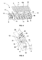
- the hybrid lighting device 1, shown in Figure 1 is adapted to illuminate with sunlight, also known as natural light, and/or generate electric power that allows the interior of a compartment to be lit or returns the electric power to the electric grid.
- sunlight also known as natural light
- the hybrid lighting device 1 comprises a plurality of hybrid modules 2, adjacent to each other, which concentrate the natural light to convert it into electric power or for lighting.
- Each hybrid module 2 comprises a collector member 3 arranged on a collector support 7, a semiconductor solar cell 4 fixed on a panel 10 arranged on the main support 8, and natural-light transmission means 5 coupled to the panel 10, the transmission means 5 being arranged separated from the solar cell 4 by a distance H.
- the hybrid lighting device 1 also comprises a substantially rectangular main support 8 that provides rigidity to the hybrid lighting device 1 and on which are arranged the collector support 7 and panel 10 respectively.
- said collector support 7 and said main support 8 may be built into a single support.
- the transmission means 5 comprise a plastic fibre optic 5b, although in other embodiments they may include a reflective mirrored pipe made of a reflective material such as silver or aluminium.
- the panel 10 is substantially flat, and is preferably made of metal, and includes holes 10b through which the corresponding fibre optic 5b is fixed to the panel 10.
- the collector member 3 mainly comprises a Fresnel lens 3b, although in other embodiments not shown in the figures, said collector member 3 may comprise a combination of lenses or another type of collector that is capable of concentrating the natural light in a certain point.
- the hybrid lighting device 1 comprises displacement means 11 that move the panel 10 in relation to the collector support 7, and thus in relation to the main support 8, the distance H between a first position shown in Figure 2 and a second position, shown in Figure 3 , said displacement being a linear displacement.
- said displacement being a linear displacement.
- the main support 8 comprises grooves 8c in the back surface and through which pass the corresponding fibre optics 5b.
- the grooves 8c are sufficiently spacious to allow the free movement of the fibre optics 5b during the linear displacement of the panel 10.
- the displacement means 11 may move the collector support 7 in relation to the panel 10, the panel 10 being fixed in this case.
- the displacement means 11, shown in detail in Figure 4 comprise means of activation 12 of the displacement, and guide means 13 that guide the relative movement between the panel 10 and the collector support 7 along the distance H.
- the guide means 13, shown in detail in Figure 4 comprise two substantially cylindrical guides 14, arranged substantially parallel to each other, aligned in the direction of displacement and fixed at the ends to side walls 8b of the main support 8, and at least one guide member 15 that moves along each guide 14. On one side the guide member 15 is passed through by the guide 14 and on the other it is fixed to the panel 10.
- the guide means 13 may include a rail that acts as a linear guide, on which at least one runner fixed to the main support 8 moves.
- the activation means 12 shown in detail in Figure 5 , are arranged substantially housed in an auxiliary support 9 fixed laterally to the main support 8, said activation means 12 comprising a motor 16, preferably a DC motor, and mechanism of conversion 17 of the rotary movement of the motor 16 into a linear movement, the conversion mechanism 17 being arranged coupled to the motor 16 and fixed to the panel 10.
- said activation means 12 comprising a motor 16, preferably a DC motor, and mechanism of conversion 17 of the rotary movement of the motor 16 into a linear movement, the conversion mechanism 17 being arranged coupled to the motor 16 and fixed to the panel 10.
- the conversion mechanism 17 thus comprises an endless screw 18 attached to the motor 16, a crown 20 attached to the endless screw 18 through which the speed of rotation is decreased and the output torque of the motor 16 is increased, and a crank connecting rod mechanism 19 attached to the crown 20.
- the crank connecting rod mechanism 19 includes a crank 21 attached to the crown 20, a main rod 22 connected to the crank 21, and a set of secondary rods 23 that have a substantially H-shaped arrangement and which connect the panel 10 to the main rod 22.
- the set of secondary rods 23, shown in detail in Figure 6 comprises central rods 24 connected to each other and to the main rod 22 by means of a central articulated joint 25, and first side rods 26, each one of which is arranged connected at one end to the corresponding central rod 24 by means of a first lateral articulated joint and at the other end, to the panel 10 by means of a second lateral articulated joint 30.
- the set of secondary rods 23 also comprise a second side rod 28a that is substantially L-shaped and a third side rod 28b, each one of which, the second side rod 28a and third side rod 28b, is arranged connected at one end, to the corresponding central rod 24 and to the corresponding first side rod 26 by means of the lateral articulated joint 27, and at the other end, to the auxiliary structure 9 by means of a respective fixed articulated joint 29.
- the mechanism of conversion 17 of the movement is a precise mechanism that is easy to assemble, as well as being a reversible mechanism, in other words the endless screw 18 may move the crown 20 on being activated by the motor 16, or the crown 20 may move the endless screw 18.
- the endless screw 18 may move the crown 20 on being activated by the motor 16, or the crown 20 may move the endless screw 18.
- a set of secondary rods 23 there is no need to include means for limiting the path travelled by the panel 10 in relation to the main support 8.
- the rod-crank mechanism may include a set of secondary rods in a rhombus arrangement.
- the conversion mechanism 17 may include a spindle that acts on the crank connecting rod mechanism 19 described above.
- the conversion mechanism 17 may include a set of gears fixed to the panel 10 and a rack fixed to the main support 8.
- a rod-crank mechanism 19 that includes a set of secondary rods 23 in a rhombus arrangement may be included.
- the hybrid lighting device 1 may be built into a photovoltaic collector panel that includes a plurality of photovoltaic modules arranged adjacent to each other and around said hybrid lighting device 1.
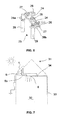
- the lighting system 31 of the invention shown in Figure 7 comprises at least one hybrid lighting device 1 arranged on the outside of the compartment 32 or building to be lit, at least one lamp 6 arranged on the inside of the compartment 32 and capable of being feed with natural light and/or the electric power provided by the hybrid lighting device 1, and control/regulation means 34.
- the control/regulation system 34 acts on the means of displacement 11 of the hybrid lighting device 1, which move the panel 10 to the second position, in which the hybrid modules 3 are arranged centred in relation to the transmission means 5. In said second position, therefore, the natural light falls on the transmission means 5, which conduct said natural light to the corresponding lamp 6.
- the electrical grid to which the lamp 6 is connected in parallel supplies the necessary remaining power to obtain the necessary artificial light, which along with the natural light, illuminates the inside of the compartment 32, adapting itself to varying requirements throughout the day.
- the lighting system 31 includes at least one sensor, not shown in the figures, that measures the level of light inside the compartment 32, and the control/regulation means 34, in accordance with the sensor measurement and the light requirements set down for said compartment 32, regulate the corresponding lamp 6 so that it generates more artificial light for the purpose of achieving ideal illumination according to the specifications laid down.
- the control/regulation means 34 act on the displacement means 11, which displace the panel 10 to the first position, in which the corresponding hybrid modules 3 are arranged centred in relation to the corresponding solar cells 4.
- the natural light in the event that it is daytime, falls on each solar cell 4, which convert said natural light into electric power, the hybrid lighting device acting as a photovoltaic panel.
- Said electric power that is generated may be stored for a subsequent use such as the supply of the light 6, or returned to the electric grid.
- the hybrid lighting device 1 may include tracking means, not shown in the figures, that enable the displacement and the orientation of said lighting device 1 in relation to the sun throughout the day to obtain increased efficiency in the concentration of sunlight.
Landscapes
- Engineering & Computer Science (AREA)
- General Engineering & Computer Science (AREA)
- Physics & Mathematics (AREA)
- Life Sciences & Earth Sciences (AREA)
- Sustainable Development (AREA)
- General Physics & Mathematics (AREA)
- Optics & Photonics (AREA)
- Architecture (AREA)
- Civil Engineering (AREA)
- Structural Engineering (AREA)
- Non-Portable Lighting Devices Or Systems Thereof (AREA)
Claims (15)
- Hybride Beleuchtungsvorrichtung, die zur Beleuchtung mit Sonnenlicht und/oder zur Erzeugung elektrischen Stroms angeordnet ist, umfassend mindstens ein Sammelelement (3), das das Sonnenlicht konzentriert, zur Versorgung mindestens einer Lampe (6) geeignete Mittel zur Übertragung (5) des Sonnenlichts, mindestens ein das auf einem Sammlerträger (7) angeordnete Sammelelement (3) umfassendes hybrides Modul (2) sowie eine auf einer Platte (10) angeordnete Photovoltaikzelle (4), dadurch charakterisiert, dass die Übertragungsmittel (5) an die Platte (10) gekoppelt sind, wobei die Platte (10) und der Sammlerträger (7) relativ zueinander zwischen einer ersten Position, in der das von jedem Sammelelement (3) konzentrierte Sonnenlicht auf die Photovoltaikzelle (4) fällt, und einer zweiten Position, in der das von jedem Sammelelement (3) konzentrierte Sonnenlicht auf die Übertragungsmittel (5) bewegbar sind.
- Hybride Beleuchtungsvorrichtung nach dem vorstehenden Anspruch, wobei die relative Verschiebung zwischen der Platte (10) und dem Sammlerträger (7) eine lineare Verschiebung ist.
- Hybride Beleuchtungsvorrichtung nach einem der vorstehenden Ansprüche, wobei sich die Platte (10) relativ zum ortsfest angeordneten Sammlerträger (7) bewegt.
- Hybride Beleuchtungsvorrichtung nach einem der vorstehenden Ansprüche, wobei die Übertragungsmittel (5) einen LWL auf Kunststoffbasis (5b) umfassen.
- Hybride Beleuchtungsvorrichtung nach einem der vorstehenden Ansprüche, wobei die Verschiebungsmittel (11) Mittel (12) zur Aktivierung der Verschiebung sowie Führungsmittel (13), die die relative Verschiebung zwischen der Platte (10) und dem Sammlerträger (7) leiten, umfassen.
- Hybride Beleuchtungsvorrichtung nach Anspruch 5, wobei die Führungsmittel (13) mindestens eine auf einem Hauptträger (8) fixierte Führung (14) sowie mindestens ein auf der Platte (10) fixiertes und an die Führung (14) relativ zur Führung (14) beweglich gekoppeltes Führungselement (15) umfassen.
- Hybride Beleuchtungsvorrichtung nach Anspruch 6, wobei die Führung (14) zylindrisch ist.
- Hybride Beleuchtungsvorrichtung nach einem der Ansprüche 6 oder 7, wobei die Führungsmittel (13) zwei Führungen (14) umfassen, die im Wesentlichen parallel zueinander angeordnet sind.
- Hybride Beleuchtungsvorrichtung nach einem der Ansprüche 5 bis 8, wobei die Aktivierungsmittel (12) einen in einem Hilfsträger (9) angeordneten Motor (16) und einen an den Motor (16) und die Platte (10) gekoppelten Mechanismus (17) zur Umwandlung der rotatorischen Bewegung des Motors (16) in eine lineare Bewegung umfassen.
- Hybride Beleuchtungsvorrichtung nach Anspruch 9, wobei der Umwandlungsmechanismus (17) eine an den Motor (16) gebundene Schnecke (18),einen an den Motor (16) gebundenen Lagerdeckel (20) sowie einen an den Lagerdeckel (20) gebundenen und auf der entsprechenden Platte (10) fixierten Kurbelstangenmechanismus (19) umfasst.
- Hybride Beleuchtungsvorrichtung nach Anspruch 10, wobei der Kurbelstangenmechanismus (19) eine an den Lagerdeckel (20) gebundene Kurbel (21), eine mit der Kurbel (21) verbundene Hauptstange (22) sowie eine Gruppe Hilfsstangen (23), die die Platte (10) mit der Hauptstange (22) verbinden, umfasst.
- Hybride Beleuchtungsvorrichtung nach Anspruch 11, wobei die Gruppe Hilfsstangen (23) miteinander und mit der Hauptstange (22) verbundene Zentralstangen (24), jeweils mit der entsprechenden Zentralstange (24) und der Platte (10) verbundene erste Seitenstangen (26) sowie jeweils mit der entsprechenden Zentralstange (24) und der entsprechenden ersten Seitenstange (26) verbundene zweite Seitenstangen (28) umfasst.
- Hybride Beleuchtungsvorrichtung nach einem der vorstehenden Ansprüche, wobei das Sammelelement (3) eine Fresnellinse umfasst.
- Beleuchtungsanlage, umfassend mindestens eine hybride Beleuchtungsvorrichtung (1) nach einem der vorstehenden Ansprüche.
- In einer Beleuchtungsanlage nach dem vorstehenden Anspruch ausgeführtes Beleuchtungsverfahren, wobei, wenn die Bedienperson die Lampe (6) einschaltet, das entsprechende Sammelelement (3) von den Verschiebungsmitteln (11) in die zweite Position verschoben wird, und auf dem entsprechenden Übertragungsmittel (5) zentriert angeordnet ist, und, wenn die Bedienperson die Lampe (6) ausschaltet, das entsprechende Sammelelement (3) in die erste Position zurückkehrt und auf der Photovoltaikzelle (4) zentriert angeordnet ist.
Applications Claiming Priority (1)
| Application Number | Priority Date | Filing Date | Title |
|---|---|---|---|
| ES200931051 | 2009-11-24 |
Publications (3)
| Publication Number | Publication Date |
|---|---|
| EP2325548A2 EP2325548A2 (de) | 2011-05-25 |
| EP2325548A3 EP2325548A3 (de) | 2012-04-11 |
| EP2325548B1 true EP2325548B1 (de) | 2013-03-27 |
Family
ID=43825317
Family Applications (1)
| Application Number | Title | Priority Date | Filing Date |
|---|---|---|---|
| EP10382301A Not-in-force EP2325548B1 (de) | 2009-11-24 | 2010-11-16 | Hybridbeleuchtungsvorrichtung und -beleuchtungsverfahren |
Country Status (1)
| Country | Link |
|---|---|
| EP (1) | EP2325548B1 (de) |
Families Citing this family (4)
| Publication number | Priority date | Publication date | Assignee | Title |
|---|---|---|---|---|
| WO2013074805A1 (en) * | 2011-11-15 | 2013-05-23 | Walsh James P | Concentrating photovoltaic collector |
| FR3000173B1 (fr) * | 2012-12-26 | 2017-10-06 | Echy | Dispositif de positionnement d'un organe transmetteur d'energie solaire par rapport a un concentrateur optique |
| CN110989153A (zh) * | 2019-12-31 | 2020-04-10 | 武汉华中天勤防务技术有限公司 | 一种光纤传导式阳光导入设备 |
| CN112902117B (zh) * | 2021-01-18 | 2025-04-01 | 深圳极光王科技股份有限公司 | 一种混灯装置及混灯方法 |
Family Cites Families (10)
| Publication number | Priority date | Publication date | Assignee | Title |
|---|---|---|---|---|
| JPS584983A (ja) * | 1981-06-30 | 1983-01-12 | Takashi Mori | 集光及び発電兼用装置 |
| US4498460A (en) * | 1983-12-27 | 1985-02-12 | Kei Mori | Solar collector |
| US4723826A (en) * | 1984-08-29 | 1988-02-09 | Whitaker Ranald O | Lens type solar collector requiring no orientation system |
| DE29823351U1 (de) * | 1998-03-10 | 1999-05-06 | Vegla Vereinigte Glaswerke Gmbh, 52066 Aachen | Verglasung zur Steuerung der Transmission von Licht |
| JP2001184913A (ja) * | 1999-12-22 | 2001-07-06 | Matsushita Electric Works Ltd | 採光装置 |
| ES2245405T3 (es) | 2001-06-22 | 2006-01-01 | Exsto Thermoplastiques | Dispositivo de separacion y de enclavamiento provisional de un batiente sobre una caja de vehiculo automovil. |
| SE0201229D0 (sv) * | 2002-04-24 | 2002-04-24 | Sandarna Parts Ab | Day Lighting Device |
| DE10319928A1 (de) * | 2003-05-02 | 2004-11-18 | SCHÄFER, Matthias | Lichteinkopplungsvorrichtung |
| JP2009047917A (ja) | 2007-08-20 | 2009-03-05 | Fujitsu Ltd | 光波長選択スイッチおよび制御方法 |
| KR20100065863A (ko) * | 2008-12-09 | 2010-06-17 | 삼성전자주식회사 | 태양광 발전 시스템 |
-
2010
- 2010-11-16 EP EP10382301A patent/EP2325548B1/de not_active Not-in-force
Also Published As
| Publication number | Publication date |
|---|---|
| EP2325548A2 (de) | 2011-05-25 |
| EP2325548A3 (de) | 2012-04-11 |
Similar Documents
| Publication | Publication Date | Title |
|---|---|---|
| KR101084721B1 (ko) | 화초형상을 가지는 태양광 발전 가로등 | |
| CN101561684A (zh) | 光伏发电定日自动跟踪控制系统 | |
| EP2325548A2 (de) | Hybridbeleuchtungsvorrichtung und -beleuchtungsverfahren | |
| KR101687183B1 (ko) | 태양광 발전 시스템을 이용한 채광 장치 및 그 채광 방법 | |
| CN201589185U (zh) | 一种聚光型可见光和太阳能电池发电混合照明系统 | |
| KR101068283B1 (ko) | 태양광 발전 트래커 장치 | |
| KR100970152B1 (ko) | 태양광을 이용한 하이브리드 조명 장치 | |
| US9897271B2 (en) | Wall-mounted sun tracking and light guiding apparatus | |
| US20150370054A1 (en) | Electromagnetic radiation system | |
| US7985920B2 (en) | Solar concentrator with self-tracking receiver | |
| CN104235736A (zh) | 可自动跟踪太阳方位角实心玻璃球折射太阳能发电路灯 | |
| CN102080800B (zh) | 光导管 | |
| KR101494827B1 (ko) | 가동식 창호거치 태양광발전 광선반 장치 | |
| KR101290126B1 (ko) | 복합 재생에너지 발전 시스템을 구비한 태양광 정밀 집광 센싱 기술을 갖는 미러 부착 조명 시스템 | |
| KR101616757B1 (ko) | 집중가열이 가능한 태양 자동 추적 집광기 | |
| KR20130016778A (ko) | 태양광 집광 장치 및 이를 이용한 하이브리드 조명 시스템 | |
| CN202103608U (zh) | 自动追踪式太阳能利用装置 | |
| EP2426402A1 (de) | Faserbeleuchtungssystem | |
| CN102864948A (zh) | 太阳能教室 | |
| CN209371086U (zh) | 一种绿色智能照明系统 | |
| KR20100065863A (ko) | 태양광 발전 시스템 | |
| Ibrahim et al. | Natural Lighting System Using Fiber Optics for Energy Efficiency | |
| CN206364765U (zh) | 一种基于太阳光聚光转为线性光源的装置 | |
| CN111371399A (zh) | 一种光纤传导太阳能光伏发电系统 | |
| CN203963782U (zh) | 太阳能发电路灯 |
Legal Events
| Date | Code | Title | Description |
|---|---|---|---|
| PUAI | Public reference made under article 153(3) epc to a published international application that has entered the european phase |
Free format text: ORIGINAL CODE: 0009012 |
|
| AK | Designated contracting states |
Kind code of ref document: A2 Designated state(s): AL AT BE BG CH CY CZ DE DK EE ES FI FR GB GR HR HU IE IS IT LI LT LU LV MC MK MT NL NO PL PT RO RS SE SI SK SM TR |
|
| AX | Request for extension of the european patent |
Extension state: BA ME |
|
| 17P | Request for examination filed |
Effective date: 20111011 |
|
| PUAL | Search report despatched |
Free format text: ORIGINAL CODE: 0009013 |
|
| AK | Designated contracting states |
Kind code of ref document: A3 Designated state(s): AL AT BE BG CH CY CZ DE DK EE ES FI FR GB GR HR HU IE IS IT LI LT LU LV MC MK MT NL NO PL PT RO RS SE SI SK SM TR |
|
| AX | Request for extension of the european patent |
Extension state: BA ME |
|
| RIC1 | Information provided on ipc code assigned before grant |
Ipc: F21V 8/00 20060101ALN20120308BHEP Ipc: F24J 2/06 20060101ALI20120308BHEP Ipc: G02B 6/00 20060101ALI20120308BHEP Ipc: F21V 33/00 20060101ALI20120308BHEP Ipc: F21S 11/00 20060101ALI20120308BHEP Ipc: F24J 2/08 20060101ALI20120308BHEP Ipc: F21S 9/03 20060101AFI20120308BHEP Ipc: H01L 31/042 20060101ALI20120308BHEP |
|
| RAP1 | Party data changed (applicant data changed or rights of an application transferred) |
Owner name: EIKA S.COOP. |
|
| RIC1 | Information provided on ipc code assigned before grant |
Ipc: G02B 6/00 20060101ALI20121116BHEP Ipc: F21V 8/00 20060101ALN20121116BHEP Ipc: F21S 9/03 20060101AFI20121116BHEP Ipc: F24J 2/08 20060101ALI20121116BHEP Ipc: F24J 2/06 20060101ALI20121116BHEP Ipc: H01L 31/042 20060101ALI20121116BHEP Ipc: F21V 33/00 20060101ALI20121116BHEP Ipc: F21S 11/00 20060101ALI20121116BHEP |
|
| GRAP | Despatch of communication of intention to grant a patent |
Free format text: ORIGINAL CODE: EPIDOSNIGR1 |
|
| GRAS | Grant fee paid |
Free format text: ORIGINAL CODE: EPIDOSNIGR3 |
|
| GRAA | (expected) grant |
Free format text: ORIGINAL CODE: 0009210 |
|
| AK | Designated contracting states |
Kind code of ref document: B1 Designated state(s): AL AT BE BG CH CY CZ DE DK EE ES FI FR GB GR HR HU IE IS IT LI LT LU LV MC MK MT NL NO PL PT RO RS SE SI SK SM TR |
|
| REG | Reference to a national code |
Ref country code: GB Ref legal event code: FG4D |
|
| REG | Reference to a national code |
Ref country code: CH Ref legal event code: EP |
|
| REG | Reference to a national code |
Ref country code: AT Ref legal event code: REF Ref document number: 603638 Country of ref document: AT Kind code of ref document: T Effective date: 20130415 |
|
| REG | Reference to a national code |
Ref country code: IE Ref legal event code: FG4D |
|
| REG | Reference to a national code |
Ref country code: DE Ref legal event code: R096 Ref document number: 602010005797 Country of ref document: DE Effective date: 20130516 |
|
| PG25 | Lapsed in a contracting state [announced via postgrant information from national office to epo] |
Ref country code: NO Free format text: LAPSE BECAUSE OF FAILURE TO SUBMIT A TRANSLATION OF THE DESCRIPTION OR TO PAY THE FEE WITHIN THE PRESCRIBED TIME-LIMIT Effective date: 20130627 Ref country code: BG Free format text: LAPSE BECAUSE OF FAILURE TO SUBMIT A TRANSLATION OF THE DESCRIPTION OR TO PAY THE FEE WITHIN THE PRESCRIBED TIME-LIMIT Effective date: 20130627 Ref country code: LT Free format text: LAPSE BECAUSE OF FAILURE TO SUBMIT A TRANSLATION OF THE DESCRIPTION OR TO PAY THE FEE WITHIN THE PRESCRIBED TIME-LIMIT Effective date: 20130327 Ref country code: SE Free format text: LAPSE BECAUSE OF FAILURE TO SUBMIT A TRANSLATION OF THE DESCRIPTION OR TO PAY THE FEE WITHIN THE PRESCRIBED TIME-LIMIT Effective date: 20130327 |
|
| REG | Reference to a national code |
Ref country code: AT Ref legal event code: MK05 Ref document number: 603638 Country of ref document: AT Kind code of ref document: T Effective date: 20130327 |
|
| REG | Reference to a national code |
Ref country code: LT Ref legal event code: MG4D |
|
| PG25 | Lapsed in a contracting state [announced via postgrant information from national office to epo] |
Ref country code: GR Free format text: LAPSE BECAUSE OF FAILURE TO SUBMIT A TRANSLATION OF THE DESCRIPTION OR TO PAY THE FEE WITHIN THE PRESCRIBED TIME-LIMIT Effective date: 20130628 Ref country code: LV Free format text: LAPSE BECAUSE OF FAILURE TO SUBMIT A TRANSLATION OF THE DESCRIPTION OR TO PAY THE FEE WITHIN THE PRESCRIBED TIME-LIMIT Effective date: 20130327 Ref country code: FI Free format text: LAPSE BECAUSE OF FAILURE TO SUBMIT A TRANSLATION OF THE DESCRIPTION OR TO PAY THE FEE WITHIN THE PRESCRIBED TIME-LIMIT Effective date: 20130327 Ref country code: SI Free format text: LAPSE BECAUSE OF FAILURE TO SUBMIT A TRANSLATION OF THE DESCRIPTION OR TO PAY THE FEE WITHIN THE PRESCRIBED TIME-LIMIT Effective date: 20130327 |
|
| REG | Reference to a national code |
Ref country code: NL Ref legal event code: VDEP Effective date: 20130327 |
|
| PG25 | Lapsed in a contracting state [announced via postgrant information from national office to epo] |
Ref country code: BE Free format text: LAPSE BECAUSE OF FAILURE TO SUBMIT A TRANSLATION OF THE DESCRIPTION OR TO PAY THE FEE WITHIN THE PRESCRIBED TIME-LIMIT Effective date: 20130327 Ref country code: HR Free format text: LAPSE BECAUSE OF FAILURE TO SUBMIT A TRANSLATION OF THE DESCRIPTION OR TO PAY THE FEE WITHIN THE PRESCRIBED TIME-LIMIT Effective date: 20130327 |
|
| PG25 | Lapsed in a contracting state [announced via postgrant information from national office to epo] |
Ref country code: CZ Free format text: LAPSE BECAUSE OF FAILURE TO SUBMIT A TRANSLATION OF THE DESCRIPTION OR TO PAY THE FEE WITHIN THE PRESCRIBED TIME-LIMIT Effective date: 20130327 Ref country code: ES Free format text: LAPSE BECAUSE OF FAILURE TO SUBMIT A TRANSLATION OF THE DESCRIPTION OR TO PAY THE FEE WITHIN THE PRESCRIBED TIME-LIMIT Effective date: 20130708 Ref country code: PT Free format text: LAPSE BECAUSE OF FAILURE TO SUBMIT A TRANSLATION OF THE DESCRIPTION OR TO PAY THE FEE WITHIN THE PRESCRIBED TIME-LIMIT Effective date: 20130729 Ref country code: AT Free format text: LAPSE BECAUSE OF FAILURE TO SUBMIT A TRANSLATION OF THE DESCRIPTION OR TO PAY THE FEE WITHIN THE PRESCRIBED TIME-LIMIT Effective date: 20130327 Ref country code: SK Free format text: LAPSE BECAUSE OF FAILURE TO SUBMIT A TRANSLATION OF THE DESCRIPTION OR TO PAY THE FEE WITHIN THE PRESCRIBED TIME-LIMIT Effective date: 20130327 Ref country code: EE Free format text: LAPSE BECAUSE OF FAILURE TO SUBMIT A TRANSLATION OF THE DESCRIPTION OR TO PAY THE FEE WITHIN THE PRESCRIBED TIME-LIMIT Effective date: 20130327 Ref country code: RO Free format text: LAPSE BECAUSE OF FAILURE TO SUBMIT A TRANSLATION OF THE DESCRIPTION OR TO PAY THE FEE WITHIN THE PRESCRIBED TIME-LIMIT Effective date: 20130327 Ref country code: IS Free format text: LAPSE BECAUSE OF FAILURE TO SUBMIT A TRANSLATION OF THE DESCRIPTION OR TO PAY THE FEE WITHIN THE PRESCRIBED TIME-LIMIT Effective date: 20130727 Ref country code: NL Free format text: LAPSE BECAUSE OF FAILURE TO SUBMIT A TRANSLATION OF THE DESCRIPTION OR TO PAY THE FEE WITHIN THE PRESCRIBED TIME-LIMIT Effective date: 20130327 |
|
| PG25 | Lapsed in a contracting state [announced via postgrant information from national office to epo] |
Ref country code: CY Free format text: LAPSE BECAUSE OF FAILURE TO SUBMIT A TRANSLATION OF THE DESCRIPTION OR TO PAY THE FEE WITHIN THE PRESCRIBED TIME-LIMIT Effective date: 20130327 Ref country code: PL Free format text: LAPSE BECAUSE OF FAILURE TO SUBMIT A TRANSLATION OF THE DESCRIPTION OR TO PAY THE FEE WITHIN THE PRESCRIBED TIME-LIMIT Effective date: 20130327 |
|
| PG25 | Lapsed in a contracting state [announced via postgrant information from national office to epo] |
Ref country code: DK Free format text: LAPSE BECAUSE OF FAILURE TO SUBMIT A TRANSLATION OF THE DESCRIPTION OR TO PAY THE FEE WITHIN THE PRESCRIBED TIME-LIMIT Effective date: 20130327 |
|
| PLBE | No opposition filed within time limit |
Free format text: ORIGINAL CODE: 0009261 |
|
| STAA | Information on the status of an ep patent application or granted ep patent |
Free format text: STATUS: NO OPPOSITION FILED WITHIN TIME LIMIT |
|
| PG25 | Lapsed in a contracting state [announced via postgrant information from national office to epo] |
Ref country code: IT Free format text: LAPSE BECAUSE OF FAILURE TO SUBMIT A TRANSLATION OF THE DESCRIPTION OR TO PAY THE FEE WITHIN THE PRESCRIBED TIME-LIMIT Effective date: 20130327 |
|
| 26N | No opposition filed |
Effective date: 20140103 |
|
| REG | Reference to a national code |
Ref country code: DE Ref legal event code: R097 Ref document number: 602010005797 Country of ref document: DE Effective date: 20140103 |
|
| PG25 | Lapsed in a contracting state [announced via postgrant information from national office to epo] |
Ref country code: MC Free format text: LAPSE BECAUSE OF FAILURE TO SUBMIT A TRANSLATION OF THE DESCRIPTION OR TO PAY THE FEE WITHIN THE PRESCRIBED TIME-LIMIT Effective date: 20130327 |
|
| REG | Reference to a national code |
Ref country code: FR Ref legal event code: ST Effective date: 20140731 |
|
| REG | Reference to a national code |
Ref country code: IE Ref legal event code: MM4A |
|
| REG | Reference to a national code |
Ref country code: DE Ref legal event code: R119 Ref document number: 602010005797 Country of ref document: DE Effective date: 20140603 |
|
| PG25 | Lapsed in a contracting state [announced via postgrant information from national office to epo] |
Ref country code: DE Free format text: LAPSE BECAUSE OF NON-PAYMENT OF DUE FEES Effective date: 20140603 |
|
| PG25 | Lapsed in a contracting state [announced via postgrant information from national office to epo] |
Ref country code: IE Free format text: LAPSE BECAUSE OF NON-PAYMENT OF DUE FEES Effective date: 20131116 |
|
| PG25 | Lapsed in a contracting state [announced via postgrant information from national office to epo] |
Ref country code: FR Free format text: LAPSE BECAUSE OF NON-PAYMENT OF DUE FEES Effective date: 20131202 |
|
| PG25 | Lapsed in a contracting state [announced via postgrant information from national office to epo] |
Ref country code: SM Free format text: LAPSE BECAUSE OF FAILURE TO SUBMIT A TRANSLATION OF THE DESCRIPTION OR TO PAY THE FEE WITHIN THE PRESCRIBED TIME-LIMIT Effective date: 20130327 |
|
| PG25 | Lapsed in a contracting state [announced via postgrant information from national office to epo] |
Ref country code: TR Free format text: LAPSE BECAUSE OF FAILURE TO SUBMIT A TRANSLATION OF THE DESCRIPTION OR TO PAY THE FEE WITHIN THE PRESCRIBED TIME-LIMIT Effective date: 20130327 |
|
| REG | Reference to a national code |
Ref country code: CH Ref legal event code: PL |
|
| GBPC | Gb: european patent ceased through non-payment of renewal fee |
Effective date: 20141116 |
|
| PG25 | Lapsed in a contracting state [announced via postgrant information from national office to epo] |
Ref country code: LI Free format text: LAPSE BECAUSE OF NON-PAYMENT OF DUE FEES Effective date: 20141130 Ref country code: HU Free format text: LAPSE BECAUSE OF FAILURE TO SUBMIT A TRANSLATION OF THE DESCRIPTION OR TO PAY THE FEE WITHIN THE PRESCRIBED TIME-LIMIT; INVALID AB INITIO Effective date: 20101116 Ref country code: RS Free format text: LAPSE BECAUSE OF FAILURE TO SUBMIT A TRANSLATION OF THE DESCRIPTION OR TO PAY THE FEE WITHIN THE PRESCRIBED TIME-LIMIT Effective date: 20130627 Ref country code: LU Free format text: LAPSE BECAUSE OF NON-PAYMENT OF DUE FEES Effective date: 20131116 Ref country code: MK Free format text: LAPSE BECAUSE OF FAILURE TO SUBMIT A TRANSLATION OF THE DESCRIPTION OR TO PAY THE FEE WITHIN THE PRESCRIBED TIME-LIMIT Effective date: 20130327 Ref country code: CH Free format text: LAPSE BECAUSE OF NON-PAYMENT OF DUE FEES Effective date: 20141130 |
|
| PG25 | Lapsed in a contracting state [announced via postgrant information from national office to epo] |
Ref country code: MT Free format text: LAPSE BECAUSE OF FAILURE TO SUBMIT A TRANSLATION OF THE DESCRIPTION OR TO PAY THE FEE WITHIN THE PRESCRIBED TIME-LIMIT Effective date: 20130327 |
|
| PG25 | Lapsed in a contracting state [announced via postgrant information from national office to epo] |
Ref country code: GB Free format text: LAPSE BECAUSE OF NON-PAYMENT OF DUE FEES Effective date: 20141116 |
|
| PG25 | Lapsed in a contracting state [announced via postgrant information from national office to epo] |
Ref country code: AL Free format text: LAPSE BECAUSE OF FAILURE TO SUBMIT A TRANSLATION OF THE DESCRIPTION OR TO PAY THE FEE WITHIN THE PRESCRIBED TIME-LIMIT Effective date: 20130327 |