EP2325568A2 - Dispositif de thermorégulation d'un support de transmission de chaleur circulant dans un circuit de chauffage - Google Patents
Dispositif de thermorégulation d'un support de transmission de chaleur circulant dans un circuit de chauffage Download PDFInfo
- Publication number
- EP2325568A2 EP2325568A2 EP10191582A EP10191582A EP2325568A2 EP 2325568 A2 EP2325568 A2 EP 2325568A2 EP 10191582 A EP10191582 A EP 10191582A EP 10191582 A EP10191582 A EP 10191582A EP 2325568 A2 EP2325568 A2 EP 2325568A2
- Authority
- EP
- European Patent Office
- Prior art keywords
- mixing chamber
- heating
- heat transfer
- transfer medium
- temperature
- Prior art date
- Legal status (The legal status is an assumption and is not a legal conclusion. Google has not performed a legal analysis and makes no representation as to the accuracy of the status listed.)
- Withdrawn
Links
Images

Classifications
-
- F—MECHANICAL ENGINEERING; LIGHTING; HEATING; WEAPONS; BLASTING
- F24—HEATING; RANGES; VENTILATING
- F24H—FLUID HEATERS, e.g. WATER OR AIR HEATERS, HAVING HEAT-GENERATING MEANS, e.g. HEAT PUMPS, IN GENERAL
- F24H1/00—Water heaters, e.g. boilers, continuous-flow heaters or water-storage heaters
- F24H1/10—Continuous-flow heaters, i.e. heaters in which heat is generated only while the water is flowing, e.g. with direct contact of the water with the heating medium
- F24H1/101—Continuous-flow heaters, i.e. heaters in which heat is generated only while the water is flowing, e.g. with direct contact of the water with the heating medium using electric energy supply
-
- F—MECHANICAL ENGINEERING; LIGHTING; HEATING; WEAPONS; BLASTING
- F24—HEATING; RANGES; VENTILATING
- F24D—DOMESTIC- OR SPACE-HEATING SYSTEMS, e.g. CENTRAL HEATING SYSTEMS; DOMESTIC HOT-WATER SUPPLY SYSTEMS; ELEMENTS OR COMPONENTS THEREFOR
- F24D3/00—Hot-water central heating systems
- F24D3/10—Feed-line arrangements, e.g. providing for heat-accumulator tanks, expansion tanks ; Hydraulic components of a central heating system
- F24D3/1091—Mixing cylinders
Definitions
- the invention relates to a device for controlling the temperature of a heat transfer medium circulated in a heating or cooling circuit with an injection valve, by means of which a heated with a heating or cooling device to a first temperature heat transfer medium to achieve the required flow temperature in a flow of the heating or cooling circuit are admixed can.
- the operation of a heat generating device used in the central heating system can be adapted to the required for all connected heating circuits identical flow temperature.
- two different heat transfer systems such as a radiator heating circuit and a floor heating to be connected to a common central heating system, so usually two different heats, each with a different flow temperature must be provided.
- the first temperature of the heat transfer medium can optionally be adapted to a first flow temperature, which requires second heating circuit a second, different from the first temperature flow temperature.
- a heating circuit can be supplied with a heat transfer medium whose flow temperature can be predetermined by the provided by the central heating system flow temperature of the heat transfer medium for another heating circuit.
- a lower flow temperature for a heating circuit is achieved or specified that either a partial flow of the more heated heat transfer medium is added to the cooler heating circuit or the cooler heating circuit is supplied with the more heated heat transfer medium, which is a sufficient proportion of already cooled heat transfer medium from the return is added.
- the flow temperature of the heating circuit can not be reliable, but only with a distance readjust the time delay between the mixing valve and the temperature measuring device.
- a refrigeration cycle requires the achievement of compliance with predetermined low temperatures. If a cooling circuit is combined with a heating circuit or if different cooling circuits are combined, the respective flow temperature must be provided and maintained in an analogous manner.
- Object of the present invention is therefore to design a device for controlling the temperature of a circulating in a heating or cooling circuit heat transfer medium so that with simple means, the flow temperature of a heating circuit regardless of the temperature of a heated with a heating or cooling device heat transfer medium can be reliably specified.
- the device has a mixing chamber, that the injection valve opens into the mixing chamber and that the Mixing chamber connections for the flow and a return of the heating or cooling circuit has.
- a mixing chamber By using a mixing chamber, rapid and reliable mixing of the heat transfer medium flowing in at different temperatures into the mixing chamber can be facilitated or ensured.
- the mixing chamber has a mixing volume of more than 0.5 liters, preferably more than 1 liter and in particular more than 2 liters.
- the mixing volume made available by the mixing chamber is expediently adapted to the respective requirements, for example with regard to the predetermined temperature difference or with regard to the flow rate of the heat transfer medium required for the heating or cooling circuit. It has been shown that a mixing volume berteiiqueses in the mixing chamber of about 2 liters for most applications can ensure adequate mixing of merged in the mixing chamber heat transfer medium with different temperatures.
- the device has a thermal sensor in the mixing chamber.
- the heat sensor is advantageously arranged at a distance from the injection valve and in the vicinity of the connection for the flow chamber leaving the mixing chamber of the heating or cooling circuit to which the heat transfer medium located in the mixing chamber is supplied.
- the temperature measured values of the heat transfer medium located in the mixing chamber which are determined by means of the heat sensor, can be used to control or regulate in a suitable manner the quantity of the higher or cooler tempered heat transfer medium metered in by the injection valve.
- the respectively required quantity of the heat transfer medium tempered with a heating or cooling device can be metered into the mixing chamber in order to achieve the flow temperature required for the flow of the heating or cooling circuit.
- a heating element is arranged in the mixing chamber.
- the temperature of the heat transfer medium in the mixing chamber can be increased without separate supply of already heated heat transfer medium to the required for the flow of the heating circuit temperature of To reach heat transfer medium.
- the mixing chamber can also be operated using an additional heating element and provide the required flow temperature of the heating circuit available when the heat generating device of the central heating system is not in operation or operation would be uneconomical.
- the heating element in particular in the transitional periods in which the operation of the heat generating device of the central heating system would be uneconomical or has already been turned off, ensure sufficient heating of the heat transfer medium and thus an operation of the heating circuit fed with it.
- the heating circuit can therefore be operated independently of the central heating system.
- the heating element has at least one electrically operable heating element.
- the one heating element or the plurality of heating elements are expediently arranged in the interior of the mixing chamber. If a regular use of the heating element is provided and is desirable or necessary for the operation of the heating circuit, the use of a plurality of mutually spaced and substantially over the entire interior of the mixing chamber extending heating elements is advantageous.
- the mixing chamber can also have a cooling device or be in thermal contact with a heat exchanger, so that the heat transfer medium can be cooled in the mixing chamber.
- the cooling device can be designed as a tube coil, which can be flowed through by an externally supplied coolant.
- the coiled cooling device can surround a designed as a heating element or heating tube heating element.
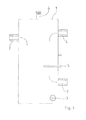
- FIG. 1 schematically shown apparatus for tempering a recirculated in a heating heat transfer medium has a mixing chamber 1 and an injection valve 2, which opens into the mixing chamber 1, and a port 3 for a flow of a heating circuit not shown and a port 4 for a return of the heating circuit.
- the heating circuit is, for example, the heating circuit of a floor heating.
- the flow temperature required for floor heating is usually lower than the flow temperature of a heating circuit for radiator radiators.
- a not shown heat generating device also not Central heating system shown generates a highly heated heat transfer medium whose temperature is higher than the flow temperature required for the flow of underfloor heating.
- both the return 4 of the heating circuit and the injection valve 2 can be supplied by the heat-generating medium more heated by the heat generating device, open into the mixing chamber 1.
- the mixing chamber 1 is a largely turbulent and effective mixing of the from the return 4 and through the injection valve 2 incoming heat transfer medium instead.
- a measuring device 5 for detecting the temperature of the heat transfer medium located in the mixing chamber 1.
- the admixture of more strongly heated heat transfer medium is regulated by the injection valve 2.
- the mixing chamber 1 additionally has a venting valve 6 and an emptying opening 7. It has been shown that in the mixing chamber 1 sufficient mixing each of the inflowing amounts of cooled or heated heat transfer medium and an accurate detection of the flow temperature of the connected heating circuit is possible.
- the mixing chamber 1 additionally arranged in the mixing chamber 1 heating rods 8, which can be put into operation by means of a control device, not shown.
- a control device not shown.
- Such a device is useful, for example, for use in conjunction with a heat pump. If at low outdoor temperatures with the heat pump, the required flow temperature of the heating circuit can not be achieved or the use of the heat pump at the given temperature differences seems uneconomical, additional heating of the present in the mixing chamber 1 heat transfer medium can be made and ensured by the heating elements 8.
Landscapes
- Engineering & Computer Science (AREA)
- Physics & Mathematics (AREA)
- Thermal Sciences (AREA)
- Chemical & Material Sciences (AREA)
- Combustion & Propulsion (AREA)
- Mechanical Engineering (AREA)
- General Engineering & Computer Science (AREA)
- Processing And Handling Of Plastics And Other Materials For Molding In General (AREA)
- Instantaneous Water Boilers, Portable Hot-Water Supply Apparatuses, And Control Of Portable Hot-Water Supply Apparatuses (AREA)
- Steam Or Hot-Water Central Heating Systems (AREA)
Applications Claiming Priority (1)
| Application Number | Priority Date | Filing Date | Title |
|---|---|---|---|
| DE200910044566 DE102009044566A1 (de) | 2009-11-17 | 2009-11-17 | Vorrichtung zum Temperieren eines in einem Heizkreislauf umgewälzten Wärmeübertragungsmediums |
Publications (2)
| Publication Number | Publication Date |
|---|---|
| EP2325568A2 true EP2325568A2 (fr) | 2011-05-25 |
| EP2325568A3 EP2325568A3 (fr) | 2015-01-21 |
Family
ID=43795195
Family Applications (1)
| Application Number | Title | Priority Date | Filing Date |
|---|---|---|---|
| EP10191582.5A Withdrawn EP2325568A3 (fr) | 2009-11-17 | 2010-11-17 | Dispositif de thermorégulation d'un support de transmission de chaleur circulant dans un circuit de chauffage |
Country Status (2)
| Country | Link |
|---|---|
| EP (1) | EP2325568A3 (fr) |
| DE (1) | DE102009044566A1 (fr) |
Cited By (1)
| Publication number | Priority date | Publication date | Assignee | Title |
|---|---|---|---|---|
| EP4617569A1 (fr) * | 2024-03-12 | 2025-09-17 | BDR Thermea Group B.V. | Réservoir et système de chauffage |
Families Citing this family (1)
| Publication number | Priority date | Publication date | Assignee | Title |
|---|---|---|---|---|
| DE102013101792B4 (de) | 2013-02-22 | 2025-11-06 | Wolf Gmbh | Wärmepumpe |
Family Cites Families (5)
| Publication number | Priority date | Publication date | Assignee | Title |
|---|---|---|---|---|
| FR2503843A1 (fr) * | 1981-04-14 | 1982-10-15 | Dietrich Sa | Vase de couplage hydraulique et de raccordement mecanique entre une source de chaleur a deux generateurs et le circuit de chauffage d'une installation |
| DE20007262U1 (de) * | 2000-04-19 | 2000-08-03 | Petrick & Wolf Energietechnik Gmbh, 02979 Neuwiese | Dampfinjektor |
| DE202005014029U1 (de) * | 2005-09-05 | 2005-11-17 | Comfort-Sinusverteiler Gmbh | Rohrverteiler für eine Heizungs- oder Kühlanlage |
| DE102006010562A1 (de) * | 2006-03-06 | 2007-09-13 | Wilo Ag | Vorrichtung zum Verteilen und Regeln eines von einer Heiz- und/oder Kühlquelle stammenden Wärmeträgers |
| DE102006025837B3 (de) * | 2006-06-02 | 2008-01-03 | Robert Bosch Gmbh | Hydraulische Weiche |
-
2009
- 2009-11-17 DE DE200910044566 patent/DE102009044566A1/de not_active Withdrawn
-
2010
- 2010-11-17 EP EP10191582.5A patent/EP2325568A3/fr not_active Withdrawn
Cited By (1)
| Publication number | Priority date | Publication date | Assignee | Title |
|---|---|---|---|---|
| EP4617569A1 (fr) * | 2024-03-12 | 2025-09-17 | BDR Thermea Group B.V. | Réservoir et système de chauffage |
Also Published As
| Publication number | Publication date |
|---|---|
| EP2325568A3 (fr) | 2015-01-21 |
| DE102009044566A1 (de) | 2011-05-19 |
Similar Documents
| Publication | Publication Date | Title |
|---|---|---|
| DE112009001136B4 (de) | Klimaanlage zur Konditionierung mehrerer Fluide | |
| EP1533116B1 (fr) | Dispositif pour contrôler la température d'une machine à imprimer | |
| EP1588076A1 (fr) | Circuit de refroidissement, en particulier pour transmission de vehicule automobile | |
| DE102017118425A1 (de) | Kreislaufsystem für ein Fahrzeug und Verfahren dazu | |
| DE29615555U1 (de) | Duschsystem | |
| DE102015203753B4 (de) | Verfahren zum Betrieb einer Wasserbehandlungsvorrichtung | |
| DE102015114474A1 (de) | Wärmepumpenanlage und Verfahren zum Betrieb einer Wärmepumpenanlage | |
| EP3594575A1 (fr) | Procédé de fonctionnement d'un système de chauffage et système de chauffage | |
| EP2924286A2 (fr) | Dispositif de vérification de pompes | |
| EP2325568A2 (fr) | Dispositif de thermorégulation d'un support de transmission de chaleur circulant dans un circuit de chauffage | |
| DE102009044674A1 (de) | Steuer- und Versorgungseinrichtung | |
| DE102008004348A1 (de) | Redundantes Klimasystem für Lokomotiven | |
| DE102011106022A1 (de) | Warmwassererzeugungs-, Speicher- und Abgabevorrichtung | |
| DE102011006653A1 (de) | Getränkeerhitzungssystem mit integrierter Verbrennungsanlage und Verfahren zum Erhitzen von Getränken | |
| EP4630734A1 (fr) | Dispositif de thermorégulation de deux milieux | |
| DE10244256A1 (de) | Heizanlage und/oder Kühlanlage mit mindestens einer Wärmequelle | |
| EP2431682A2 (fr) | Corps de chauffe doté d'un composant d'aération et bâtonnet chauffant électrique | |
| DE10019302A1 (de) | Wärmepumpe zur Heizungs- und Brauchwassererwärmung | |
| DE202015101006U1 (de) | Wasserbehandlungsvorrichtung | |
| DE102015203293B4 (de) | Gebäude | |
| EP3943819B1 (fr) | Système de ventilation à air chaud à récupération de chaleur | |
| DE102023118543A1 (de) | Verfahren und Vorrichtung zum Betrieb einer Kälteanlage mit Abwärmenutzung | |
| DE102008022808A1 (de) | Brennstoffzellensystem für ein Fahrzeug | |
| DE3215582A1 (de) | Heizungsanlage sowie hierfuer geeigneter heizkoerper | |
| EP4357682A1 (fr) | Dispositif de pompe à chaleur et procédé de fonctionnement d'un dispositif de pompe à chaleur |
Legal Events
| Date | Code | Title | Description |
|---|---|---|---|
| PUAI | Public reference made under article 153(3) epc to a published international application that has entered the european phase |
Free format text: ORIGINAL CODE: 0009012 |
|
| AK | Designated contracting states |
Kind code of ref document: A2 Designated state(s): AL AT BE BG CH CY CZ DE DK EE ES FI FR GB GR HR HU IE IS IT LI LT LU LV MC MK MT NL NO PL PT RO RS SE SI SK SM TR |
|
| AX | Request for extension of the european patent |
Extension state: BA ME |
|
| PUAL | Search report despatched |
Free format text: ORIGINAL CODE: 0009013 |
|
| AK | Designated contracting states |
Kind code of ref document: A3 Designated state(s): AL AT BE BG CH CY CZ DE DK EE ES FI FR GB GR HR HU IE IS IT LI LT LU LV MC MK MT NL NO PL PT RO RS SE SI SK SM TR |
|
| AX | Request for extension of the european patent |
Extension state: BA ME |
|
| RIC1 | Information provided on ipc code assigned before grant |
Ipc: F24D 3/10 20060101AFI20141217BHEP Ipc: F24H 1/10 20060101ALI20141217BHEP |
|
| STAA | Information on the status of an ep patent application or granted ep patent |
Free format text: STATUS: THE APPLICATION IS DEEMED TO BE WITHDRAWN |
|
| 18D | Application deemed to be withdrawn |
Effective date: 20150602 |