EP2325713A2 - Procédés et systèmes pour le mouvement d'un dispositif robotique à l'aide d'un signal vidéo - Google Patents
Procédés et systèmes pour le mouvement d'un dispositif robotique à l'aide d'un signal vidéo Download PDFInfo
- Publication number
- EP2325713A2 EP2325713A2 EP10190545A EP10190545A EP2325713A2 EP 2325713 A2 EP2325713 A2 EP 2325713A2 EP 10190545 A EP10190545 A EP 10190545A EP 10190545 A EP10190545 A EP 10190545A EP 2325713 A2 EP2325713 A2 EP 2325713A2
- Authority
- EP
- European Patent Office
- Prior art keywords
- robotic device
- mobile robotic
- information
- edge
- received information
- Prior art date
- Legal status (The legal status is an assumption and is not a legal conclusion. Google has not performed a legal analysis and makes no representation as to the accuracy of the status listed.)
- Granted
Links
Images



Classifications
-
- G—PHYSICS
- G05—CONTROLLING; REGULATING
- G05D—SYSTEMS FOR CONTROLLING OR REGULATING NON-ELECTRIC VARIABLES
- G05D1/00—Control of position, course, altitude or attitude of land, water, air or space vehicles, e.g. using automatic pilots
- G05D1/02—Control of position or course in two dimensions
- G05D1/021—Control of position or course in two dimensions specially adapted to land vehicles
- G05D1/0231—Control of position or course in two dimensions specially adapted to land vehicles using optical position detecting means
- G05D1/0246—Control of position or course in two dimensions specially adapted to land vehicles using optical position detecting means using a video camera in combination with image processing means
-
- G—PHYSICS
- G05—CONTROLLING; REGULATING
- G05D—SYSTEMS FOR CONTROLLING OR REGULATING NON-ELECTRIC VARIABLES
- G05D1/00—Control of position, course, altitude or attitude of land, water, air or space vehicles, e.g. using automatic pilots
- G05D1/02—Control of position or course in two dimensions
- G05D1/021—Control of position or course in two dimensions specially adapted to land vehicles
- G05D1/0255—Control of position or course in two dimensions specially adapted to land vehicles using acoustic signals, e.g. ultra-sonic singals
-
- G—PHYSICS
- G05—CONTROLLING; REGULATING
- G05D—SYSTEMS FOR CONTROLLING OR REGULATING NON-ELECTRIC VARIABLES
- G05D1/00—Control of position, course, altitude or attitude of land, water, air or space vehicles, e.g. using automatic pilots
- G05D1/02—Control of position or course in two dimensions
- G05D1/021—Control of position or course in two dimensions specially adapted to land vehicles
- G05D1/0257—Control of position or course in two dimensions specially adapted to land vehicles using a radar
-
- G—PHYSICS
- G05—CONTROLLING; REGULATING
- G05D—SYSTEMS FOR CONTROLLING OR REGULATING NON-ELECTRIC VARIABLES
- G05D1/00—Control of position, course, altitude or attitude of land, water, air or space vehicles, e.g. using automatic pilots
- G05D1/02—Control of position or course in two dimensions
- G05D1/021—Control of position or course in two dimensions specially adapted to land vehicles
- G05D1/0268—Control of position or course in two dimensions specially adapted to land vehicles using internal positioning means
- G05D1/0274—Control of position or course in two dimensions specially adapted to land vehicles using internal positioning means using mapping information stored in a memory device
Definitions
- Mobile robotic devices have minimized the human effort involved in performing everyday tasks. For example, automatic cleaning devices help maintaining and cleaning surfaces, such as hardwood floors, carpet and the like. Mobile robotic devices are useful, but location detection can be a challenge for the operation of such devices.
- a method of navigating an area using a mobile robotic device may include receiving, from a video camera, information associated with an edge located on a surface, determining, by a mobile robotic device, a position of the mobile robotic device on the surface relative to the edge and adjusting the position of the mobile robotic device based on a proximity of the mobile robotic device to the edge.
- the method may include using the received information to move the mobile robotic device from the determined position along a path.
- the path may be substantially parallel to the edge, and may be located a distance from a reference point on the mobile robotic device during movement of the mobile robotic device.
- a system for navigating an area using a mobile robotic device may include a mobile robotic device including a processing device and a computer-readable storage medium and a video camera in communication with the mobile robotic device.
- the computer-readable storage medium may include one or more programming instructions for receiving, from the video camera, information associated with an edge located on a surface in an area, determining a position of the mobile robotic device on the surface relative to the edge, and adjusting the position of the mobile robotic device based on a proximity of the mobile robotic device to the edge.
- the one or more programming instructions for adjusting the position of the mobile robotic device may comprise one or more programming instructions for using the received information to move the mobile robotic device from the determined position along a path.
- the path may be substantially parallel to the edge, and may be located a distance from a reference point on the mobile robotic device during movement of the mobile robotic device.
- a method of navigating an environment using a mobile robotic device may include sending, to a video camera, a request for information comprising a color value and a tolerance value, receiving, from the video camera, information associated with an area corresponding to the color value and the tolerance value and using the received information to adjust a position of the mobile robotic device on a surface of the environment.
- a system for navigating an environment using a mobile robotic device may include a mobile robotic device having a processing device and a computer-readable storage medium, and a video camera in communication with the mobile robotic device.
- the computer-readable storage medium may include one or more programming instructions for sending, to the video camera, a request for information comprising a color value and a tolerance value, receiving, from the video camera, information associated with an area corresponding to the color value and the tolerance value, and using the received information to adjust a position of the mobile robotic device on a surface of the environment.
- the mobile robotic device of the present methods and systems may comprise an automatic cleaning device, and may include cleaning, by the automatic cleaning device, the surface along the path.
- Such embodiments may include determining one or more characteristics associated with the surface along the path, wherein the one or more characteristics comprise one or more of the following: hard wood flooring, tile flooring, carpeting, a high-traffic area, and a low-traffic area, may further include determining a cleaning method based on the determined one or more characteristics, and may further include applying the cleaning method to the surface along the path by performing one or more of the following: vacuuming the surface along the path, scrubbing the surface along the path, and waxing the surface along the path.
- FIG. 1 illustrates an exemplary robotic system according to an embodiment.
- a robotic system may include a mobile robotic device 100 and a video camera 105 .
- the mobile robotic device 100 may be an autonomous device that is capable of automatically navigating its environment.
- a mobile robotic device 100 may include a processing device, a computer-readable storage medium and/or the like.
- a mobile robotic device 100 may be in communication with one or more external processing devices, computer-readable storage mediums and/or the like.
- the video camera 105 may be a color video camera, a black and white video camera and/or the like. In an embodiment, the video camera 105 may be mounted on a front portion of a mobile robotic device 100 . In an alternate embodiment, the video camera 105 may be mounted on a rear portion, a side portion or other portion of the mobile robotic device 100 .
- the video camera 105 may include a processing device, a computer-readable storage medium and/or the like. In an embodiment, the video camera 105 may be in communication with the mobile robotic device 100 and/or one or more external processing devices, computer-readable storage mediums and/or the like. For example, the video camera 105 may collect information about the mobile robotic device's surroundings such as coordinates, navigational information, visual information and/or the like. The video camera 105 may provide this information to the mobile robotic device 100.
- the video camera 105 may be a CMUcam3.
- the CMUcam3 is an ARM7TDMI-based programmable embedded computer vision sensor developed by Carnegie Mellon University. Additional and/or alternate video cameras may be used within the scope of this disclosure.
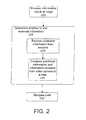
- FIG. 2 illustrates an exemplary method of navigating a mobile robotic device according to an embodiment.
- a mobile robotic device may receive 200 information regarding its surrounding environment from a video camera.
- a video camera may perform image processing on a video frame to locate one or more substantially straight lines in the image.
- a substantially straight line may be representative of a boundary or edge between rooms, floor types and/or the like.
- a video camera may be able to detect an edge between two adjoining rooms.
- a video camera may be able to detect an edge between a carpeted floor and a tile floor.
- an edge may be detected based on color contrast and/or the like.
- the mobile robotic device may receive 200 information regarding an edge from the video camera.
- the information may include values associated with the slope, the intercept and/or the error of a line detected by the video camera.
- the slope, intercept and/or error associated with a substantially straight lines from an image of a surface, such as a ground surface, a floor surface or other surface over which the mobile robotic device is travelling may be provided to the mobile robotic device.
- the video camera may repetitively send updated information to the mobile robotic device.
- the video camera may send the mobile robotic device updated slope values, intercept values and/or error values associated with a detected line several times per second.
- a mobile robotic device may use this information to determine its position relative to the detected edge. For example, a mobile robotic device may compare information about its current position, such as its coordinates, heading and/or the like, with information received from the video camera regarding the edge. The mobile robotic device may use this comparison to determine its position relative to the edge, its distance away from the edge and/or the like.
- a mobile robotic device may detect an edge located in the direction of the mobile robotic device's movement. For example, a mobile robotic device may detect an edge in front of the mobile robotic device when the mobile robotic device is moving forward. A mobile robotic device may detect an edge that is substantially perpendicular to its movement. For example, a mobile robotic device may detect an edge associated with a wall or other barrier that the mobile robotic device is approaching. In an embodiment, a mobile robotic device may adjust its motion based on its proximity to a detected edge. For example, a mobile robotic device may turn itself around or otherwise change its course when it comes within two feet of the detected edge. Additional and/or alternate proximities may be used within the scope of this disclosure.
- the mobile robotic device may determine 205 whether to use any of the information received from the video camera to adjust its position. For example, the mobile robotic device may receive 210 positional information from one or more sensors, such as sonar, radar and/or the like. The mobile robotic device may compare 215 the information that it receives from its sensors and the information that it receives from the video camera to information from a map of an area or environment in which the mobile robotic device is navigating.
- the mobile robotic device may receive 210 positional information from one or more sensors, such as sonar, radar and/or the like.
- the mobile robotic device may compare 215 the information that it receives from its sensors and the information that it receives from the video camera to information from a map of an area or environment in which the mobile robotic device is navigating.
- a map may be generated by the mobile robotic device and/or another computing device during the mobile robotic device's first navigation of the area.
- the mobile robotic device may be manually controlled through an area during which time the mobile robotic device may generate and store a map of the navigated area.
- the mobile robotic device may compare 215 the information it receives 210 from its sensors and the information it receives from the video camera to the digital representation of the map to determine which information to use.
- the mobile robotic device may use the information that has the least amount of error as compared to the mobile robotic device's current position.
- a mobile robotic device may determine a current position using a map. It may compare the information received from its sensor and the information it receives from its video camera to determine which information has the least amount of error relative to its current position. The mobile robotic device may adjust its position based on the information associated with the least amount of error.
- the mobile robotic device may use the information associated with an edge and its determined position to navigate 220 a path.
- the mobile robotic device may navigate 220 a path relative to the edge. For example, the mobile robotic device may navigate 220 a path that begins at the determined position and that runs parallel to the edge. Alternatively, the mobile robotic device may navigate 220 a path that begins at the determined position and that is not parallel to the edge.
- the mobile robotic device may navigate 220 a path such that the edge is located a certain distance from a reference point on the mobile robotic device.
- the reference point may be a side portion, a front portion, a back portion and/or the like of the mobile robotic device.
- a mobile robotic device may use a detected line as a side registration by tracking the line on the right or left side of the mobile robotic device.
- a mobile robotic device may include an automatic cleaning device.
- An automatic cleaning device may be a mobile robotic device that can automatically navigate and clean surfaces, such as floors.
- FIG. 3 illustrates an exemplary method of cleaning an area with an automatic cleaning device according to an embodiment.
- an automatic cleaning device may receive 300 information regarding an edge from the video camera.
- the information may include values associated with the slope, the intercept and/or the error of a line detected by the video camera.
- an automatic cleaning device may use this received information to determine its position relative to the detected edge. For example, an automatic cleaning device may compare information about its current position, such as its coordinates, heading and/or the like, with information received from the video camera regarding the edge.
- the automatic cleaning device may determine 305 whether to use any of the information received from the video camera to adjust its position.
- the automatic cleaning device may receive 310 positional information from one or more sensors, such as sonar, radar and/or the like.
- the automatic device may compare 315 the information that it receives from its sensors and the information that it receives from the video camera to information from a map of an area in which the automatic cleaning device is navigating.
- the automatic cleaning device may compare 315 the information it receives 310 from its sensors and the information it receives from the video camera to the digital representation of the map to determine which information to use.
- the automatic cleaning device may use the information that has the least amount of error as compared to the automatic cleaning device's current position. For example, an automatic cleaning device may determine a current position using a map. It may compare the information received from its sensor and the information it receives from its video camera to determine which information has the least amount of error relative to its current position. The automatic cleaning device may adjust its position based on the information associated with the least amount of error.
- the automatic cleaning device may use the information associated with an edge and its determined position to navigate 320 a path.
- the automatic cleaning device may navigate 320 a path relative to the edge.
- the automatic cleaning device may navigate 320 a path that begins at the determined position and that runs parallel to the edge.
- the automatic cleaning device may navigate 320 the path such that the edge is located a certain distance from a reference point on the automatic cleaning device.
- the reference point may be a side portion, a front portion, a back portion and/or the like of the automatic cleaning device.
- an automatic cleaning device may use a detected line as a side registration by tracking the line on the right or left side of the automatic cleaning device.
- the automatic cleaning device may clean 325 at least a portion of its navigated path.
- an automatic cleaning device may be able to determine one or more characteristics corresponding to its determined position.
- a characteristic may include, for example, a floor type, such as hard wood, tile, carpet and/or the like.
- a characteristic may include whether the position is in a high-traffic area, a low-traffic area and/or the like.
- an automatic cleaning device may determine an appropriate cleaning method based on the determined characteristics. For example, the automatic cleaning device may vacuum a carpeted area, scrub and/or wax a hardwood or tile area and/or the like.
- FIG. 4 illustrates an exemplary diagram of a mobile robotic device's movement according to an embodiment.
- a mobile robotic device 400 may track an edge 405 between a carpeted portion of a floor 410 and a tiled portion of a floor 415 .
- the mobile robotic device 400 may move relative to the edge 405 .
- the mobile robotic device 400 may move along the illustrated path 420 , which may run parallel to the edge 405.
- a mobile robotic device may navigate its surroundings based on its location relative to an area of a particular color.
- An area may be a surface area, an item, a landmark and/or the like.
- a mobile robotic device may navigate an area based on its relative position to a green chair located in a room.
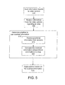
- FIG. 5 illustrates an exemplary method of navigating a mobile robotic device according to an embodiment.
- a mobile robotic device may send 500 an information request to the video camera.
- the information request may include an indication of a color and a tolerance associated with the color.
- an indication of a color may be a color name, a number associated with a color and/or the like.
- a mobile robotic device may send 500 an instruction to the video camera asking it to search for the color green.
- the instruction may also include a tolerance value which may instruct the video camera as to a range of colors that may be accepted.
- the mobile robotic device may receive 505 information from the video camera.
- the mobile robotic device may receive 505 from the video camera coordinates associated with a substantially central portion of an area corresponding to the specified color.
- the mobile robotic device may also receive 505 coordinates of one or more corners of a rectangle that encompasses the detected area.
- the video camera may send the mobile robotic device coordinates of the corners of a bounding box that is just large enough to completely encompass the detected area.
- the mobile robotic device may receive a number of pixels of the color that were detected in the area.
- the mobile robotic device may receive 505 from the video camera a numerical value associated with a detected color and/or an associated tolerance range. For example, each color that is detected by the video camera may be assigned a numerical value. The numerical value associated with a detected color may be compared to a numerical value associated with the requested color. If the numerical value associated with the detected color is within a tolerance range (i.e., the numerical value associated with the requested color +/- the tolerance value), the detected color may be accepted. The mobile robotic device may receive from the video camera the value of the detected color and/or the tolerance range.
- the mobile robotic device may determine 510 whether to use any of the information received from the video camera in navigating its path. For example, the mobile robotic device may receive 515 positional information from one or more sensors, such as sonar, radar and/or the like. In an embodiment, the mobile robotic device may compare 520 the information that it receives from its sensors and the information that it receives from the video camera to information from a map of an area in which the mobile robotic device is navigating.
- the mobile robotic device may determine 510 whether to use any of the information received from the video camera in navigating its path. For example, the mobile robotic device may receive 515 positional information from one or more sensors, such as sonar, radar and/or the like. In an embodiment, the mobile robotic device may compare 520 the information that it receives from its sensors and the information that it receives from the video camera to information from a map of an area in which the mobile robotic device is navigating.
- a map may be generated by the mobile robotic device and/or another computing device during the mobile robotic device's first navigation of the area.
- the mobile robotic device may be manually controlled through an area during which time the mobile robotic device may generate and store a map of the navigated area.
- a map of an area may be generated manually.
- a may be generated by a user and a digital representation of the map may be stored electronically.
- the mobile robotic device may compare 520 the information it receives 515 from its sensors and the information it receives from the video camera to the digital representation of the map to determine which information to use. In an embodiment, the mobile robotic device may use the information that has the least amount of error as compared to the mobile robotic device's current position. For example, a mobile robotic device may determine a current position using a map. It may compare the information received from its sensor and the information it receives from its video camera to determine which information has the least amount of error relative to its current position. The mobile robotic device may adjust its position based on the information associated with the least amount of error.
- the mobile robotic device may adjust 525 its position based on the most accurate information.
- the mobile robotic device may use the information to adjust 525 its position, heading and/or the like.
- an estimated position of the mobile robotic device may be determined.
- the estimated position may include coordinates, a heading and/or the like.
- an actual position may be determined based on the information associated with the detected area that is received by the mobile robotic device.
- the estimated position may be compared to the actual position, and the mobile robotic device may adjust 525 its position to compensate for any positional error that may exist. For example, the mobile robotic device may navigate from its actual position to the estimated position.
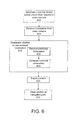
- FIG. 6 illustrates an exemplary method of navigating an automatic cleaning device according to an embodiment.
- an automatic cleaning device may send 600 an information request to the video camera.
- the information request may include an indication of a color and a tolerance associated with the color.
- the instruction may also include a tolerance value which may instruct the video camera as to a range of colors that may be accepted.
- the automatic cleaning device may receive 605 information from the video camera.
- the automatic cleaning device may receive 605 from the video camera coordinates associated with a substantially central portion of an area corresponding to the specified color.
- the automatic cleaning device may also receive 605 coordinates of one or more corners of a rectangle that encompasses the detected area.
- the automatic cleaning device may receive a number of pixels of the color that were detected in the area.
- the automatic cleaning device may receive 605 from the video camera a numerical value associated with a detected color and/or an associated tolerance range. For example, each color that is detected by the video camera may be assigned a numerical value. The numerical value associated with a detected color may be compared to a numerical value associated with the requested color. If the numerical value associated with the detected color is within a tolerance range (i.e., the numerical value associated with the requested color +/- the tolerance value), the detected color may be accepted. The automatic cleaning device may receive from the video camera the value of the detected color and/or the tolerance range.
- the automatic cleaning device may determine 610 whether to use any of the information received from the video camera in navigating its path. For example, the automatic cleaning device may receive 615 positional information from one or more sensors, such as sonar, radar and/or the like. In an embodiment, the automatic cleaning device may compare 620 the information that it receives from its sensors and the information that it receives from the video camera to information from a map of an area in which the automatic cleaning device is navigating.
- the automatic cleaning device may determine 610 whether to use any of the information received from the video camera in navigating its path. For example, the automatic cleaning device may receive 615 positional information from one or more sensors, such as sonar, radar and/or the like. In an embodiment, the automatic cleaning device may compare 620 the information that it receives from its sensors and the information that it receives from the video camera to information from a map of an area in which the automatic cleaning device is navigating.
- a map may be generated by the automatic cleaning device and/or another computing device during the automatic cleaning device's first navigation of the area.
- the automatic cleaning device may be manually controlled through an area during which time the mobile robotic device may generate and store a map of the navigated area.
- the mobile robotic device may compare 620 the information it receives 615 from its sensors and the information it receives from the video camera to the digital representation of the map to determine which information to use.
- the automatic cleaning device may use the information that has the least amount of error as compared to the automatic cleaning device's current position. For example, an automatic cleaning device may determine a current position using a map. It may compare the information received from its sensor and the information it receives from its video camera to determine which information has the least amount of error relative to its current position. The automatic cleaning device may adjust its position based on the information associated with the least amount of error.
- the automatic cleaning device may adjust 625 its position based on the most accurate information.
- the automatic cleaning device may use the information to adjust 625 its position, heading and/or the like.
- an estimated position of the automatic cleaning device may be determined.
- the estimated position may include coordinates, a heading and/or the like.
- an actual position may be determined based on the information associated with the detected area that is received by the automatic cleaning device.
- the estimated position may be compared to the actual position, and the automatic cleaning device may adjust 625 its position to compensate for any positional error that may exist. For example, the automatic cleaning device may navigate from its actual position to the estimated position.
- the automatic cleaning device may clean 630 at least a portion of its navigated path.
- an automatic cleaning device may be able to determine one or more characteristics corresponding to its determined position.
- a characteristic may include, for example, a floor type, such as hard wood, tile, carpet and/or the like.
- a characteristic may include whether the position is in a high-traffic area, a low-traffic area and/or the like.
- an automatic cleaning device may determine an appropriate cleaning method based on the determined characteristics. For example, the automatic cleaning device may vacuum a carpeted area, scrub and/or wax a hardwood or tile area and/or the like.
Landscapes
- Engineering & Computer Science (AREA)
- Physics & Mathematics (AREA)
- Computer Vision & Pattern Recognition (AREA)
- Multimedia (AREA)
- Electromagnetism (AREA)
- Aviation & Aerospace Engineering (AREA)
- Radar, Positioning & Navigation (AREA)
- Remote Sensing (AREA)
- General Physics & Mathematics (AREA)
- Automation & Control Theory (AREA)
- Control Of Position, Course, Altitude, Or Attitude Of Moving Bodies (AREA)
Applications Claiming Priority (2)
| Application Number | Priority Date | Filing Date | Title |
|---|---|---|---|
| US12/616,577 US8679260B2 (en) | 2009-11-11 | 2009-11-11 | Methods and systems for movement of an automatic cleaning device using video signal |
| US12/616,452 US8423225B2 (en) | 2009-11-11 | 2009-11-11 | Methods and systems for movement of robotic device using video signal |
Publications (3)
| Publication Number | Publication Date |
|---|---|
| EP2325713A2 true EP2325713A2 (fr) | 2011-05-25 |
| EP2325713A3 EP2325713A3 (fr) | 2012-03-14 |
| EP2325713B1 EP2325713B1 (fr) | 2013-06-05 |
Family
ID=43629494
Family Applications (1)
| Application Number | Title | Priority Date | Filing Date |
|---|---|---|---|
| EP10190545.3A Active EP2325713B1 (fr) | 2009-11-11 | 2010-11-09 | Procédés et systèmes pour le mouvement d'un dispositif robotique à l'aide d'un signal vidéo |
Country Status (1)
| Country | Link |
|---|---|
| EP (1) | EP2325713B1 (fr) |
Families Citing this family (1)
| Publication number | Priority date | Publication date | Assignee | Title |
|---|---|---|---|---|
| US10885768B2 (en) | 2018-02-12 | 2021-01-05 | Tennant Company | Systems and methods for measuring performance of site maintenance |
Family Cites Families (6)
| Publication number | Priority date | Publication date | Assignee | Title |
|---|---|---|---|---|
| US5442552A (en) * | 1993-03-16 | 1995-08-15 | The Regents Of The University Of California | Robotic cultivator |
| US6611738B2 (en) * | 1999-07-12 | 2003-08-26 | Bryan J. Ruffner | Multifunctional mobile appliance |
| RU2220643C2 (ru) * | 2001-04-18 | 2004-01-10 | Самсунг Гванджу Электроникс Ко., Лтд. | Автоматическое чистящее устройство, автоматическая чистящая система и способ управления этой системой (варианты) |
| US8577538B2 (en) * | 2006-07-14 | 2013-11-05 | Irobot Corporation | Method and system for controlling a remote vehicle |
| KR100877072B1 (ko) * | 2007-06-28 | 2009-01-07 | 삼성전자주식회사 | 이동 로봇을 위한 맵 생성 및 청소를 동시에 수행하는 방법및 장치 |
| KR100877071B1 (ko) * | 2007-07-18 | 2009-01-07 | 삼성전자주식회사 | 파티클 필터 기반의 이동 로봇의 자세 추정 방법 및 장치 |
-
2010
- 2010-11-09 EP EP10190545.3A patent/EP2325713B1/fr active Active
Also Published As
| Publication number | Publication date |
|---|---|
| EP2325713A3 (fr) | 2012-03-14 |
| EP2325713B1 (fr) | 2013-06-05 |
Similar Documents
| Publication | Publication Date | Title |
|---|---|---|
| US9609991B2 (en) | Methods and systems for movement of an automatic cleaning device using video signal | |
| US8423225B2 (en) | Methods and systems for movement of robotic device using video signal | |
| US12038756B2 (en) | Intelligent cleaning robot | |
| US20230064687A1 (en) | Restricting movement of a mobile robot | |
| US11960304B2 (en) | Localization and mapping using physical features | |
| JP6772129B2 (ja) | 移動ロボットにおける光学式走行距離センサの使用のためのシステム及び方法 | |
| US11402850B2 (en) | Robotic cleaning device with operating speed variation based on environment | |
| US9911226B2 (en) | Method for cleaning or processing a room by means of an autonomously mobile device | |
| EP2888603B1 (fr) | Système de positionnement de robot | |
| US9597804B2 (en) | Auto-cleaning system, cleaning robot and method of controlling the cleaning robot | |
| US11215998B2 (en) | Method for the navigation and self-localization of an autonomously moving processing device | |
| JP7345132B2 (ja) | 自律走行型掃除機、自律走行型掃除機の制御方法、及び、プログラム | |
| EP2325713B1 (fr) | Procédés et systèmes pour le mouvement d'un dispositif robotique à l'aide d'un signal vidéo | |
| US20240126263A1 (en) | Method for determining a selection area in an environment for a mobile device | |
| KR102121458B1 (ko) | 자동 충전을 위한 로봇 청소기의 경로 추정 방법 및 이를 이용한 로봇 청소기 | |
| US20210191415A1 (en) | Area profile map learning for robotic device |
Legal Events
| Date | Code | Title | Description |
|---|---|---|---|
| PUAI | Public reference made under article 153(3) epc to a published international application that has entered the european phase |
Free format text: ORIGINAL CODE: 0009012 |
|
| AK | Designated contracting states |
Kind code of ref document: A2 Designated state(s): AL AT BE BG CH CY CZ DE DK EE ES FI FR GB GR HR HU IE IS IT LI LT LU LV MC MK MT NL NO PL PT RO RS SE SI SK SM TR |
|
| AX | Request for extension of the european patent |
Extension state: BA ME |
|
| PUAL | Search report despatched |
Free format text: ORIGINAL CODE: 0009013 |
|
| AK | Designated contracting states |
Kind code of ref document: A3 Designated state(s): AL AT BE BG CH CY CZ DE DK EE ES FI FR GB GR HR HU IE IS IT LI LT LU LV MC MK MT NL NO PL PT RO RS SE SI SK SM TR |
|
| AX | Request for extension of the european patent |
Extension state: BA ME |
|
| RIC1 | Information provided on ipc code assigned before grant |
Ipc: G05D 1/02 20060101AFI20120207BHEP |
|
| 17P | Request for examination filed |
Effective date: 20120913 |
|
| GRAP | Despatch of communication of intention to grant a patent |
Free format text: ORIGINAL CODE: EPIDOSNIGR1 |
|
| GRAP | Despatch of communication of intention to grant a patent |
Free format text: ORIGINAL CODE: EPIDOSNIGR1 |
|
| GRAS | Grant fee paid |
Free format text: ORIGINAL CODE: EPIDOSNIGR3 |
|
| GRAA | (expected) grant |
Free format text: ORIGINAL CODE: 0009210 |
|
| AK | Designated contracting states |
Kind code of ref document: B1 Designated state(s): AL AT BE BG CH CY CZ DE DK EE ES FI FR GB GR HR HU IE IS IT LI LT LU LV MC MK MT NL NO PL PT RO RS SE SI SK SM TR |
|
| REG | Reference to a national code |
Ref country code: GB Ref legal event code: FG4D |
|
| REG | Reference to a national code |
Ref country code: CH Ref legal event code: EP |
|
| REG | Reference to a national code |
Ref country code: AT Ref legal event code: REF Ref document number: 616003 Country of ref document: AT Kind code of ref document: T Effective date: 20130615 |
|
| REG | Reference to a national code |
Ref country code: IE Ref legal event code: FG4D |
|
| REG | Reference to a national code |
Ref country code: DE Ref legal event code: R096 Ref document number: 602010007530 Country of ref document: DE Effective date: 20130801 |
|
| REG | Reference to a national code |
Ref country code: AT Ref legal event code: MK05 Ref document number: 616003 Country of ref document: AT Kind code of ref document: T Effective date: 20130605 |
|
| PG25 | Lapsed in a contracting state [announced via postgrant information from national office to epo] |
Ref country code: SE Free format text: LAPSE BECAUSE OF FAILURE TO SUBMIT A TRANSLATION OF THE DESCRIPTION OR TO PAY THE FEE WITHIN THE PRESCRIBED TIME-LIMIT Effective date: 20130605 Ref country code: NO Free format text: LAPSE BECAUSE OF FAILURE TO SUBMIT A TRANSLATION OF THE DESCRIPTION OR TO PAY THE FEE WITHIN THE PRESCRIBED TIME-LIMIT Effective date: 20130905 Ref country code: AT Free format text: LAPSE BECAUSE OF FAILURE TO SUBMIT A TRANSLATION OF THE DESCRIPTION OR TO PAY THE FEE WITHIN THE PRESCRIBED TIME-LIMIT Effective date: 20130605 Ref country code: ES Free format text: LAPSE BECAUSE OF FAILURE TO SUBMIT A TRANSLATION OF THE DESCRIPTION OR TO PAY THE FEE WITHIN THE PRESCRIBED TIME-LIMIT Effective date: 20130916 Ref country code: LT Free format text: LAPSE BECAUSE OF FAILURE TO SUBMIT A TRANSLATION OF THE DESCRIPTION OR TO PAY THE FEE WITHIN THE PRESCRIBED TIME-LIMIT Effective date: 20130605 Ref country code: SI Free format text: LAPSE BECAUSE OF FAILURE TO SUBMIT A TRANSLATION OF THE DESCRIPTION OR TO PAY THE FEE WITHIN THE PRESCRIBED TIME-LIMIT Effective date: 20130605 Ref country code: GR Free format text: LAPSE BECAUSE OF FAILURE TO SUBMIT A TRANSLATION OF THE DESCRIPTION OR TO PAY THE FEE WITHIN THE PRESCRIBED TIME-LIMIT Effective date: 20130906 Ref country code: FI Free format text: LAPSE BECAUSE OF FAILURE TO SUBMIT A TRANSLATION OF THE DESCRIPTION OR TO PAY THE FEE WITHIN THE PRESCRIBED TIME-LIMIT Effective date: 20130605 |
|
| REG | Reference to a national code |
Ref country code: NL Ref legal event code: VDEP Effective date: 20130605 |
|
| REG | Reference to a national code |
Ref country code: LT Ref legal event code: MG4D |
|
| PG25 | Lapsed in a contracting state [announced via postgrant information from national office to epo] |
Ref country code: HR Free format text: LAPSE BECAUSE OF FAILURE TO SUBMIT A TRANSLATION OF THE DESCRIPTION OR TO PAY THE FEE WITHIN THE PRESCRIBED TIME-LIMIT Effective date: 20130605 Ref country code: BG Free format text: LAPSE BECAUSE OF FAILURE TO SUBMIT A TRANSLATION OF THE DESCRIPTION OR TO PAY THE FEE WITHIN THE PRESCRIBED TIME-LIMIT Effective date: 20130905 Ref country code: RS Free format text: LAPSE BECAUSE OF FAILURE TO SUBMIT A TRANSLATION OF THE DESCRIPTION OR TO PAY THE FEE WITHIN THE PRESCRIBED TIME-LIMIT Effective date: 20130605 |
|
| PG25 | Lapsed in a contracting state [announced via postgrant information from national office to epo] |
Ref country code: LV Free format text: LAPSE BECAUSE OF FAILURE TO SUBMIT A TRANSLATION OF THE DESCRIPTION OR TO PAY THE FEE WITHIN THE PRESCRIBED TIME-LIMIT Effective date: 20130605 |
|
| PG25 | Lapsed in a contracting state [announced via postgrant information from national office to epo] |
Ref country code: EE Free format text: LAPSE BECAUSE OF FAILURE TO SUBMIT A TRANSLATION OF THE DESCRIPTION OR TO PAY THE FEE WITHIN THE PRESCRIBED TIME-LIMIT Effective date: 20130605 Ref country code: IS Free format text: LAPSE BECAUSE OF FAILURE TO SUBMIT A TRANSLATION OF THE DESCRIPTION OR TO PAY THE FEE WITHIN THE PRESCRIBED TIME-LIMIT Effective date: 20131005 Ref country code: BE Free format text: LAPSE BECAUSE OF FAILURE TO SUBMIT A TRANSLATION OF THE DESCRIPTION OR TO PAY THE FEE WITHIN THE PRESCRIBED TIME-LIMIT Effective date: 20130605 Ref country code: PT Free format text: LAPSE BECAUSE OF FAILURE TO SUBMIT A TRANSLATION OF THE DESCRIPTION OR TO PAY THE FEE WITHIN THE PRESCRIBED TIME-LIMIT Effective date: 20131007 Ref country code: SK Free format text: LAPSE BECAUSE OF FAILURE TO SUBMIT A TRANSLATION OF THE DESCRIPTION OR TO PAY THE FEE WITHIN THE PRESCRIBED TIME-LIMIT Effective date: 20130605 Ref country code: CZ Free format text: LAPSE BECAUSE OF FAILURE TO SUBMIT A TRANSLATION OF THE DESCRIPTION OR TO PAY THE FEE WITHIN THE PRESCRIBED TIME-LIMIT Effective date: 20130605 |
|
| PG25 | Lapsed in a contracting state [announced via postgrant information from national office to epo] |
Ref country code: NL Free format text: LAPSE BECAUSE OF FAILURE TO SUBMIT A TRANSLATION OF THE DESCRIPTION OR TO PAY THE FEE WITHIN THE PRESCRIBED TIME-LIMIT Effective date: 20130605 Ref country code: RO Free format text: LAPSE BECAUSE OF FAILURE TO SUBMIT A TRANSLATION OF THE DESCRIPTION OR TO PAY THE FEE WITHIN THE PRESCRIBED TIME-LIMIT Effective date: 20130605 Ref country code: PL Free format text: LAPSE BECAUSE OF FAILURE TO SUBMIT A TRANSLATION OF THE DESCRIPTION OR TO PAY THE FEE WITHIN THE PRESCRIBED TIME-LIMIT Effective date: 20130605 |
|
| PLBE | No opposition filed within time limit |
Free format text: ORIGINAL CODE: 0009261 |
|
| STAA | Information on the status of an ep patent application or granted ep patent |
Free format text: STATUS: NO OPPOSITION FILED WITHIN TIME LIMIT |
|
| PG25 | Lapsed in a contracting state [announced via postgrant information from national office to epo] |
Ref country code: DK Free format text: LAPSE BECAUSE OF FAILURE TO SUBMIT A TRANSLATION OF THE DESCRIPTION OR TO PAY THE FEE WITHIN THE PRESCRIBED TIME-LIMIT Effective date: 20130605 |
|
| 26N | No opposition filed |
Effective date: 20140306 |
|
| PG25 | Lapsed in a contracting state [announced via postgrant information from national office to epo] |
Ref country code: IT Free format text: LAPSE BECAUSE OF FAILURE TO SUBMIT A TRANSLATION OF THE DESCRIPTION OR TO PAY THE FEE WITHIN THE PRESCRIBED TIME-LIMIT Effective date: 20130605 |
|
| REG | Reference to a national code |
Ref country code: DE Ref legal event code: R097 Ref document number: 602010007530 Country of ref document: DE Effective date: 20140306 |
|
| PG25 | Lapsed in a contracting state [announced via postgrant information from national office to epo] |
Ref country code: MC Free format text: LAPSE BECAUSE OF FAILURE TO SUBMIT A TRANSLATION OF THE DESCRIPTION OR TO PAY THE FEE WITHIN THE PRESCRIBED TIME-LIMIT Effective date: 20130605 |
|
| REG | Reference to a national code |
Ref country code: FR Ref legal event code: ST Effective date: 20140731 |
|
| REG | Reference to a national code |
Ref country code: IE Ref legal event code: MM4A |
|
| REG | Reference to a national code |
Ref country code: DE Ref legal event code: R119 Ref document number: 602010007530 Country of ref document: DE Effective date: 20140603 |
|
| PG25 | Lapsed in a contracting state [announced via postgrant information from national office to epo] |
Ref country code: DE Free format text: LAPSE BECAUSE OF NON-PAYMENT OF DUE FEES Effective date: 20140603 |
|
| PG25 | Lapsed in a contracting state [announced via postgrant information from national office to epo] |
Ref country code: IE Free format text: LAPSE BECAUSE OF NON-PAYMENT OF DUE FEES Effective date: 20131109 |
|
| PG25 | Lapsed in a contracting state [announced via postgrant information from national office to epo] |
Ref country code: FR Free format text: LAPSE BECAUSE OF NON-PAYMENT OF DUE FEES Effective date: 20131202 |
|
| PG25 | Lapsed in a contracting state [announced via postgrant information from national office to epo] |
Ref country code: SM Free format text: LAPSE BECAUSE OF FAILURE TO SUBMIT A TRANSLATION OF THE DESCRIPTION OR TO PAY THE FEE WITHIN THE PRESCRIBED TIME-LIMIT Effective date: 20130605 |
|
| PG25 | Lapsed in a contracting state [announced via postgrant information from national office to epo] |
Ref country code: TR Free format text: LAPSE BECAUSE OF FAILURE TO SUBMIT A TRANSLATION OF THE DESCRIPTION OR TO PAY THE FEE WITHIN THE PRESCRIBED TIME-LIMIT Effective date: 20130605 Ref country code: CY Free format text: LAPSE BECAUSE OF FAILURE TO SUBMIT A TRANSLATION OF THE DESCRIPTION OR TO PAY THE FEE WITHIN THE PRESCRIBED TIME-LIMIT Effective date: 20130605 |
|
| PG25 | Lapsed in a contracting state [announced via postgrant information from national office to epo] |
Ref country code: LU Free format text: LAPSE BECAUSE OF NON-PAYMENT OF DUE FEES Effective date: 20131109 Ref country code: MK Free format text: LAPSE BECAUSE OF FAILURE TO SUBMIT A TRANSLATION OF THE DESCRIPTION OR TO PAY THE FEE WITHIN THE PRESCRIBED TIME-LIMIT Effective date: 20130605 Ref country code: HU Free format text: LAPSE BECAUSE OF FAILURE TO SUBMIT A TRANSLATION OF THE DESCRIPTION OR TO PAY THE FEE WITHIN THE PRESCRIBED TIME-LIMIT; INVALID AB INITIO Effective date: 20101109 |
|
| PG25 | Lapsed in a contracting state [announced via postgrant information from national office to epo] |
Ref country code: MT Free format text: LAPSE BECAUSE OF FAILURE TO SUBMIT A TRANSLATION OF THE DESCRIPTION OR TO PAY THE FEE WITHIN THE PRESCRIBED TIME-LIMIT Effective date: 20130605 |
|
| PG25 | Lapsed in a contracting state [announced via postgrant information from national office to epo] |
Ref country code: AL Free format text: LAPSE BECAUSE OF FAILURE TO SUBMIT A TRANSLATION OF THE DESCRIPTION OR TO PAY THE FEE WITHIN THE PRESCRIBED TIME-LIMIT Effective date: 20130605 |
|
| REG | Reference to a national code |
Ref country code: CH Ref legal event code: PUE Owner name: DIVERSEY, INC., US Free format text: FORMER OWNER: INTELLIBOT ROBOTICS LLC, US |
|
| REG | Reference to a national code |
Ref country code: GB Ref legal event code: 732E Free format text: REGISTERED BETWEEN 20200116 AND 20200122 |
|
| P01 | Opt-out of the competence of the unified patent court (upc) registered |
Effective date: 20230506 |
|
| PGFP | Annual fee paid to national office [announced via postgrant information from national office to epo] |
Ref country code: GB Payment date: 20231123 Year of fee payment: 14 |
|
| PGFP | Annual fee paid to national office [announced via postgrant information from national office to epo] |
Ref country code: CH Payment date: 20231202 Year of fee payment: 14 |
|
| REG | Reference to a national code |
Ref country code: CH Ref legal event code: PL |
|
| REG | Reference to a national code |
Ref country code: CH Ref legal event code: PL |
|
| GBPC | Gb: european patent ceased through non-payment of renewal fee |
Effective date: 20241109 |
|
| PG25 | Lapsed in a contracting state [announced via postgrant information from national office to epo] |
Ref country code: CH Free format text: LAPSE BECAUSE OF NON-PAYMENT OF DUE FEES Effective date: 20241130 |
|
| PG25 | Lapsed in a contracting state [announced via postgrant information from national office to epo] |
Ref country code: GB Free format text: LAPSE BECAUSE OF NON-PAYMENT OF DUE FEES Effective date: 20241109 |