EP2325992B1 - Dispositif onduleur, système de commande de dispositif onduleur, système de commande de moteur, et procédé de commande de dispositif onduleur - Google Patents
Dispositif onduleur, système de commande de dispositif onduleur, système de commande de moteur, et procédé de commande de dispositif onduleur Download PDFInfo
- Publication number
- EP2325992B1 EP2325992B1 EP09812929.9A EP09812929A EP2325992B1 EP 2325992 B1 EP2325992 B1 EP 2325992B1 EP 09812929 A EP09812929 A EP 09812929A EP 2325992 B1 EP2325992 B1 EP 2325992B1
- Authority
- EP
- European Patent Office
- Prior art keywords
- inverter
- heat sink
- temperature
- motor
- thermal
- Prior art date
- Legal status (The legal status is an assumption and is not a legal conclusion. Google has not performed a legal analysis and makes no representation as to the accuracy of the status listed.)
- Active
Links
Images


Classifications
-
- H—ELECTRICITY
- H02—GENERATION; CONVERSION OR DISTRIBUTION OF ELECTRIC POWER
- H02M—APPARATUS FOR CONVERSION BETWEEN AC AND AC, BETWEEN AC AND DC, OR BETWEEN DC AND DC, AND FOR USE WITH MAINS OR SIMILAR POWER SUPPLY SYSTEMS; CONVERSION OF DC OR AC INPUT POWER INTO SURGE OUTPUT POWER; CONTROL OR REGULATION THEREOF
- H02M7/00—Conversion of AC power input into DC power output; Conversion of DC power input into AC power output
- H02M7/42—Conversion of DC power input into AC power output without possibility of reversal
- H02M7/44—Conversion of DC power input into AC power output without possibility of reversal by static converters
- H02M7/48—Conversion of DC power input into AC power output without possibility of reversal by static converters using discharge tubes with control electrode or semiconductor devices with control electrode
- H02M7/53—Conversion of DC power input into AC power output without possibility of reversal by static converters using discharge tubes with control electrode or semiconductor devices with control electrode using devices of a triode or transistor type requiring continuous application of a control signal
- H02M7/537—Conversion of DC power input into AC power output without possibility of reversal by static converters using discharge tubes with control electrode or semiconductor devices with control electrode using devices of a triode or transistor type requiring continuous application of a control signal using semiconductor devices only, e.g. single switched pulse inverters
- H02M7/5387—Conversion of DC power input into AC power output without possibility of reversal by static converters using discharge tubes with control electrode or semiconductor devices with control electrode using devices of a triode or transistor type requiring continuous application of a control signal using semiconductor devices only, e.g. single switched pulse inverters in a bridge configuration
- H02M7/53871—Conversion of DC power input into AC power output without possibility of reversal by static converters using discharge tubes with control electrode or semiconductor devices with control electrode using devices of a triode or transistor type requiring continuous application of a control signal using semiconductor devices only, e.g. single switched pulse inverters in a bridge configuration with automatic control of output voltage or current
- H02M7/53875—Conversion of DC power input into AC power output without possibility of reversal by static converters using discharge tubes with control electrode or semiconductor devices with control electrode using devices of a triode or transistor type requiring continuous application of a control signal using semiconductor devices only, e.g. single switched pulse inverters in a bridge configuration with automatic control of output voltage or current with analogue control of three-phase output
-
- H—ELECTRICITY
- H02—GENERATION; CONVERSION OR DISTRIBUTION OF ELECTRIC POWER
- H02M—APPARATUS FOR CONVERSION BETWEEN AC AND AC, BETWEEN AC AND DC, OR BETWEEN DC AND DC, AND FOR USE WITH MAINS OR SIMILAR POWER SUPPLY SYSTEMS; CONVERSION OF DC OR AC INPUT POWER INTO SURGE OUTPUT POWER; CONTROL OR REGULATION THEREOF
- H02M7/00—Conversion of AC power input into DC power output; Conversion of DC power input into AC power output
- H02M7/42—Conversion of DC power input into AC power output without possibility of reversal
- H02M7/44—Conversion of DC power input into AC power output without possibility of reversal by static converters
- H02M7/48—Conversion of DC power input into AC power output without possibility of reversal by static converters using discharge tubes with control electrode or semiconductor devices with control electrode
-
- H—ELECTRICITY
- H02—GENERATION; CONVERSION OR DISTRIBUTION OF ELECTRIC POWER
- H02P—CONTROL OR REGULATION OF ELECTRIC MOTORS, ELECTRIC GENERATORS OR DYNAMO-ELECTRIC CONVERTERS; CONTROLLING TRANSFORMERS, REACTORS OR CHOKE COILS
- H02P29/00—Arrangements for regulating or controlling electric motors, appropriate for both AC and DC motors
- H02P29/60—Controlling or determining the temperature of the motor or of the drive
- H02P29/68—Controlling or determining the temperature of the motor or of the drive based on the temperature of a drive component or a semiconductor component
-
- H—ELECTRICITY
- H02—GENERATION; CONVERSION OR DISTRIBUTION OF ELECTRIC POWER
- H02P—CONTROL OR REGULATION OF ELECTRIC MOTORS, ELECTRIC GENERATORS OR DYNAMO-ELECTRIC CONVERTERS; CONTROLLING TRANSFORMERS, REACTORS OR CHOKE COILS
- H02P8/00—Arrangements for controlling dynamo-electric motors rotating step by step
- H02P8/12—Control or stabilisation of current
-
- H—ELECTRICITY
- H05—ELECTRIC TECHNIQUES NOT OTHERWISE PROVIDED FOR
- H05K—PRINTED CIRCUITS; CASINGS OR CONSTRUCTIONAL DETAILS OF ELECTRIC APPARATUS; MANUFACTURE OF ASSEMBLAGES OF ELECTRICAL COMPONENTS
- H05K7/00—Constructional details common to different types of electric apparatus
- H05K7/20—Modifications to facilitate cooling, ventilating, or heating
- H05K7/2089—Modifications to facilitate cooling, ventilating, or heating for power electronics, e.g. for inverters for controlling motor
- H05K7/20945—Thermal management, e.g. inverter temperature control
Definitions
- the present invention relates to an inverter apparatus and a method of controlling the same.
- the present invention relates to a function of providing protection under overload conditions.
- Patent Document 1 describes a technology for calculating the surface temperature and the internal temperature of a motor by using a thermal model having generated heat and the ambient temperature as variables. The technology is used for providing protection under overload conditions (hereinafter referred to as "overload protection") while maintaining the maximum output power of a motor even when use conditions and the ambient temperature varies.
- overload protection protection under overload conditions
- Patent Document 2 describes a technology for performing overload protection while maintaining the maximum output power of a motor even when the operating condition of the motor is changed in such a way that the motor is stopped or rotated at a very low speed.
- Patent Document 3 describes a technology for automatically performing derating, which is an operation of lowering the rating in accordance with differences in environmental conditions and operating conditions, such as the ambient temperature and a DC voltage.
- Patent Document 4 describes a technology for estimating an operable time in accordance with the operating state of an electric power system.
- Patent Document 5 Japanese Unexamined Patent Application Publication No. 08-33104 (Patent Document 5) describes a technology for measuring, in real time, a transient thermal resistance of a cooling fin in order to keep the junction temperature of a semiconductor device to be below a threshold.
- Patent Documents discuss overload protection assuming that the thermal characteristic of a heat sink is limited to a specific state.
- n° EP 1 193 756 discloses a method for monitoring a device with power semiconductors, in particular an inverter.
- a temperature of at least one component of the device and / or of the environment is determined directly or indirectly.
- Actions are started if at least one measured or estimated temperature exceeds a threshold.
- the temperature estimations are based on a predefined model with predefined thermal parameters. The model thus lacks accuracy if the thermal properties of the heat sink differ from the predefined thermal properties.
- a thermal model which has data on generated heat and data on ambient temperature as variables, is constructed by using a command current that is estimated from operating conditions, such as the output frequency and the DC voltage, and thereby the junction temperature of a power semiconductor device of a power module is calculated.
- Such a structure has a problem in that, when mounting a power module on an unknown heat sink, an optimal thermal model corresponding to the mounting condition cannot be constructed.
- the term "unknown heat sink” refers to a heat sink whose data on thermal resistance and thermal capacity has not been obtained.
- An object of the representative inventions of the present application which address such a problem, is to provide an inverter apparatus that includes a power module mounted on an unknown heat sink and that can perform overload protection while maintaining a high performance of the apparatus.
- the inverter mounted on an unknown heat sink can be effectively protected from an overload state, because the values of the thermal resistance and the thermal capacity of the heat sink can be estimated.
- the estimated values can be automatically changed on the basis of the temperature of the inverter, because the estimated values are calculated on the basis of the temperature of the inverter and driving of the inverter is controlled on the basis of the estimated values.
- a change in the thermal characteristic and a change in the environment can be estimated with a high precision, because the standard values of the thermal resistance and the thermal capacity of a standard heat sink are stored.
- an inverter mounted on an unknown heat sink can be effectively protected from an overload state.
- a motor current can be applied without rotating the motor, because a current commander that is independent of a current controller is provided. That is, the temperature of an inverter can be increased without rotating the motor, and the estimated values are calculated.
- the thermal resistance and the thermal capacity of an unknown heat sink can be efficiently estimated, because the second current command corresponds to a plurality of command patterns of operating times based on the thermal time constant that is calculated from the standard values.
- a current limit curve for overload protection of an unknown heat sink can be automatically set by derating a current limit curve for overload protection of the standard heat sink by using temperature data estimated from the standard values of the thermal resistance and the thermal capacity of a standard heat sink. Therefore, overload protection can be effectively performed while maintaining a high performance of a power module, even when the installation environment of the inverter apparatus changes or the thermal property of a heat sink changes.
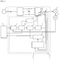
- Fig. 1 illustrates an inverter apparatus I according to the present embodiment.
- a power source 12 which supplies electric power to the inverter apparatus I, is disposed outside the inverter apparatus I.
- a host controller 15 such as a CPU, which controls the inverter apparatus I, is also disposed outside the inverter apparatus I.
- the inverter apparatus I, the power source 12, and the host controller 15 are collectively called an inverter control system.
- the inverter apparatus I, the motor 13, and the position detector 14 are collectively called a motor control system, or a system further including the power source 12 and the host controller 15 may be called a motor control system.
- An inverter apparatus I includes a controller C, a converter 1, and an inverter 3.
- the controller C includes a smoothing capacitor 2, a current detector 4, a velocity controller 5, a current limiter 6, a current controller 7, an overload protector 8, an estimator 9, a mode switch 10, a d/q-axis current commander 11, and temperature sensors 16 and 17.
- at least the inverter 3 is mounted on a heat sink, which is not illustrated in Fig. 1 .
- the inverter 3 includes a plurality of power semiconductor devices, and is modularized. This module may be called a power module. The structure of a power module, which is well-known, is not described in detail here. If the entire inverter apparatus I is modularized, the module may be called an inverter module.
- the converter 1 which is connected to the power source 12, transforms the voltage of electric power and supplies the electric power to the inverter 3.
- a smoothing capacitor 2 is serially connected between the converter 1 and the inverter 3.
- the inverter 3 converts DC power so that the motor 13 can operate in accordance with a command, and supplies the power to the motor 13.
- the velocity controller 5 generates a current command signal from a velocity command sent from the host controller 15 and a velocity command generated from a position signal sent from the position sensor 14, and supplies the current command signal to the current limiter 6 through the mode switch 10.
- the current limiter 6 generates a new current command in response to the current command signal.
- the current controller 7 generates a voltage command by using the current signal generated by the current detector 14, generates a PWM gate signal drive, and drives the power semiconductor device installed in the inverter 3.
- the inverter 3 includes a sensor 16 for detecting the temperature of the inverter 3.
- the sensor 16 measures the temperature of the heat sink (ambient temperature) in the environment in which the inverter is installed.
- the overload protector 8 estimates the junction temperature of the semiconductor device of the inverter 3 from the motor current detected by the current detector 4 and the ambient temperature.
- the overload protector 8 calculates the current limit value for the motor on the basis of the estimated temperature.
- the current limiter 6 generates a stop signal for stopping driving of the motor, and outputs the signal to the current controller 7.
- the current controller 7 controls driving of the semiconductor device of the inverter 3, and protects the inverter 3 from overload.
- the inverter apparatus I includes a sensor 17 that detects the temperature of a power module 200.
- the sensor 17 measures the temperature of the power module 200 of the inverter 3 including a power semiconductor device 201.
- the sensor 16 is disposed in the case of the inverter 3, and measures the temperature of air in the case of the inverter 3.
- the inverter 3 is mounted on a heat sink 203.
- the estimator 9 has a function of calculating the thermal resistance and the thermal capacity of an unknown heat sink 204 illustrated in Fig. 3 .
- the estimator 9 estimates the thermal resistance and the thermal capacity of the heat sink 204 by comparing the motor current with the ambient temperature of the inverter 3 and data on the thermal resistance and the thermal capacity of the standard heat sink 203.
- the term "unknown heat sink” refers to a heat sink whose data on the thermal resistance and the thermal capacity has not been obtained.
- standard heat sink refers to a heat sink whose data on the thermal resistance and the thermal capacity has been obtained.
- the estimator 9 includes a storage that stores the values (standard values) of the thermal resistance and the thermal capacity of the standard heat sink 203.
- the estimated values calculated by the estimator 9 are input to the overload protector 8, and the overload protector 8 calculates the junction temperature of the semiconductor device 201 of the inverter 3 by using a thermal equivalent circuit including a motor current, the ambient temperature of the inverter 3, and the estimated thermal resistance and the estimated thermal capacity of the unknown heat sink.
- the current limiter 6 performs current limiting on the basis of a current limit value for the motor derived from the calculation result, whereby the inverter 3 is protected from overload. In the present embodiment, this protection may be referred to as overload protection.
- the mode switch 10 and the d/q-axis current commander 11 have a function of increasing the temperature of the inverter 3 by energizing the motor 13 without rotating the motor 13 in order to estimate the thermal resistance and the thermal capacity of the unknown heat sink 204.
- a velocity command is sent from the host controller 15 through the velocity commander 5 to the current limiter 6, which performs current limiting on the velocity command.
- the current controller 7 converts the velocity command to a current command, generates a PWM gate signal, transmits the command for driving the semiconductor device 201 of the inverter 3, and the motor 13 is driven.
- a switching signal from the host controller 15 is sent to the mode switch 10, and a current command from the host controller is directly provided to the d/q-axis current commander 11.
- Fig. 4 illustrates a thermal equivalent circuit that is used by the overload protector 8 in order to estimate the junction temperature of the semiconductor device 201 from the ambient temperature of the inverter 3 and the motor current.
- the elements corresponding to those of Figs. 2 and 3 are denoted by the same numerals.
- Fig. 4 illustrates a thermal equivalent circuit that is used by the overload protector 8 in order to estimate the junction temperature of the semiconductor device 201 from the ambient temperature of the inverter 3 and the motor current.
- 20 denotes the generated heat Q 0
- 21 denotes the thermal capacity Cc of the case
- 22 denotes the thermal capacity Cf of the heat sink 204
- 23 denotes the thermal resistance Rjc between the junction and the case
- 24 denotes the thermal resistance Rcf between the case and the heat sink
- 25 denotes the thermal resistance Rfa between the heat sink 204 and the ambient temperature
- 26 is the junction temperature Tj
- 27 is the temperature Tc of the case
- 28 is the temperature Tf of the heat sink 204
- 29 is the ambient temperature Ta.
- Tf' Ta + Rfa ⁇ Q 1 ⁇ e ⁇ t 1 / Rfa ⁇ Cf
- Fig. 5 a method of estimating the thermal resistance and the thermal capacity of the unknown heat sink 204 will be described.
- 31 denotes the temperature variation of the standard heat sink 203
- 32 denotes the temperature variation of an unknown heat sink 204-1
- 33 denotes the temperature variation of an unknown heat sink 204-2
- 35 denotes the thermal time constant ⁇ of the standard heat sink
- 36 denotes the time t1 based on the time constant of the standard heat sink 203
- 37 denotes a time t2 based on the time constant of the standard heat sink 203.
- the temperature variation 31 of the standard heat sink 203 and the temperature variations 32 and 33 of the unknown heat sinks can be measured by the sensor 16 of the inverter 3.
- the estimator 9 stores the thermal resistance Rfa between the standard heat sink 203 and ambient temperature, which is obtained from the temperature variation 31 of the standard heat sink 203, the thermal capacity Cf of the standard heat sink, and the thermal time constant ⁇ 35 of the standard heat sink that is calculated from these values.
- the unknown heat sink 204-1 has a thermal resistance the same as the thermal resistance of the standard heat sink 203 and a thermal capacity that is half the thermal capacity of the standard heat sink 203.
- the unknown heat sink 204-2 has a thermal resistance that is twice the thermal resistance of the standard heat sink and a thermal capacity that is the same as the thermal capacity of the standard heat sink.
- the temperature variation 33 of the unknown heat sink 204-2 is approximately the same as the temperature variation 31 of the standard heat sink.
- the temperature variation 32 of the unknown heat sink 204-1 which has s thermal capacity that is half the thermal capacity of the standard heat sink, is approximately double the temperature variation of the standard heat sink at the time 1/10-T.
- the thermal capacity Cfx of the unknown heat sink is estimated by using the following equation from the temperature variation Tt1 of the standard heat sink and the temperature variation Tt1X of the unknown heat sink at time 1/10 ⁇ .
- CfX denotes the thermal capacity of the unknown heat sink
- Cf denotes the thermal capacity of the standard heat sink.
- Cfx Cf ⁇ Tt 1 / Tt 1 ⁇ X
- the thermal resistance Rfax of the unknown heat sink is estimated to be the same as Rfa. If there is a difference from the temperature variation 31 at time ⁇ , Rfax is estimated by performing calculation using equation (2) in the same manner. It is not necessary that the measurement time t3 be the same as the time constant ⁇ of the standard heat sink.
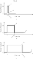
- Fig. 6(a) illustrates a current command pattern for energizing only for a period of the time t1 (0.1 ⁇ )
- Fig. 6(b) illustrates a current command pattern for energizing only for a period of the time t2 (0.5 ⁇ )
- Fig. 6(c) illustrates a current command pattern for energizing only for a period of the time ⁇ , in which 41 denotes an Id-axis command value 1, 42 denotes an Iq-axis command value 1, 43 denotes an Id-axis command value 2, and 44 denotes an Id-axis command value 3.
- the phase angle of the motor is moved to a predetermined position.
- a command is issued to the velocity controller 5 in a normal velocity command mode, and the phase angle of the motor 13 is adjusted to a specific phase angle on the basis of the signal of the position sensor 14.
- the host controller 15 sends a signal to the control mode switch 10, the control mode is changed so that the normal velocity control that performs a current control is temporarily stopped, the d/q-axis current commander 11 directly supplies a current command value to the inverter 3, and a motor current is generated.
- a command signal having the same magnitude as the rating current is supplied, for a period of the time t1, to the Id-axis that generates a reactive current of a motor.
- a zero current command is supplied, for a period of the time t1, to the Iq-axis that generates an active current for the motor.
- a gate signal of each phase of the semiconductor device functions so that a current corresponding to the phase angle of the motor is distributed to the coil of the motor in accordance with the magnitude of the Id current command.
- the motor can be energized without being rotated, because the zero current command is supplied to the Iq-axis that generates an active current for the motor.
- the thermal resistance and the thermal capacity of an unknown heat sink can be calculated by, as in the case of Fig. 6(a) , changing the length of the time period of the current command as illustrated in Figs. 6(b) and 6(c) .
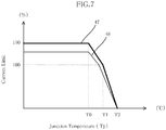
- a method of providing a current limit to the overload protector 8 by using the estimated thermal resistance and the estimated thermal capacity of the unknown heat sink will be described.
- 47 denotes a current limit curve for overload protection of the standard heat sink
- 48 denotes a current limit curve for overload protection of an inverter mounted on the unknown heat sink 204-1.
- the current limit curve 48 is obtained by multiplying the current limit curve of the overload protection of the standard heat sink by the reciprocal of the ratio of the temperature estimate of the temperature variation 32 at the time constant t1, which is calculated from the estimated values of the thermal resistance and the thermal capacity of the unknown heat sink 204-1, and the temperature data on the standard heat sink.
- the derated curve is set as the current limit curve 47 for overload protection of the unknown heat sink, data for the overload protector illustrated in Fig. 1 is automatically updated, and overload protection is performed.
- an inverter apparatus that can automatically set the current limit value of the heat sink is realized.
- the method performs current limiting for overload protection by estimating the thermal resistance and the thermal capacity of an unknown heat sink. Therefore, the method is also applicable to life assessment related to degradation of thermal resistance between a heat sink and a power module of a general purpose inverter or a servo amplifier to which the heat sink is attached.
Landscapes
- Engineering & Computer Science (AREA)
- Power Engineering (AREA)
- Microelectronics & Electronic Packaging (AREA)
- Physics & Mathematics (AREA)
- Thermal Sciences (AREA)
- Inverter Devices (AREA)
- Control Of Ac Motors In General (AREA)
Claims (9)
- Dispositif formant onduleur (I) comprenant :un radiateur (203) ;un premier détecteur (16) qui détecte une température du radiateur ;un onduleur (3) comportant un module de puissance comportant un dispositif à semi-conducteur, l'onduleur étant fixé sur le radiateur ;un second détecteur (17) qui détecte une température du module de puissance ;un élément d'estimation qui calcule des valeurs estimées d'une résistance thermique et d'une capacité thermique du radiateur, l'élément d'estimation comportant un dispositif de mémorisation qui mémorise des valeurs standard d'une résistance thermique et d'une capacité thermique d'un radiateur standard,l'élément d'estimation étant configuré de manière à calculer les valeurs estimées de la résistance thermique et de la capacité thermique du radiateur par rapport aux variations de température des radiateurs standard et estimé, mesurées par le premier détecteur (16) à des instants qui sont fonction de la constante de temps thermique du radiateur standard ; etune unité de commande qui commande l'attaque de l'onduleur sur la base des valeurs estimées.
- Dispositif formant onduleur selon la revendication 1, dans lequel l'onduleur est protégé d'une surcharge en limitant le niveau d'attaque de l'onduleur.
- Dispositif formant onduleur selon les revendications 1 ou 2,
dans lequel l'unité de commande comporte :une unité de commande de courant qui délivre une première consigne de courant à l'onduleur dans un "mode normal",un dispositif de commande de courant qui délivre une seconde consigne de courant à l'onduleur dans un mode d'estimation dans lequel l'élément d'estimation calcule les valeurs estimées, etun commutateur qui commute entre le "mode normal" et le mode d'estimation en réponse à un signal de commutation. - Dispositif formant onduleur selon la revendication 3, dans lequel la seconde consigne de courant correspond à une pluralité de profils de consigne d'instants de fonctionnement sur la base d'une constante de temps thermique qui est calculée à partir des valeurs standard.
- Dispositif de commande d'onduleur raccordé à un dispositif formant onduleur selon l'une quelconque des revendications 3 à 4, le dispositif de commande d'onduleur comportant une unité de commande qui délivre le signal de commutation au commutateur.
- Dispositif de commande de moteur comprenant :un moteur raccordé à l'onduleur selon l'une quelconque des revendications 3 à 5,dans lequel, dans le mode d'estimation, le dispositif formant onduleur augmente une température de l'onduleur en alimentant le moteur sans faire tourner le moteur en réponse à la seconde consigne de courant.
- Procédé de commande d'un dispositif formant onduleur (I), le procédé comprenant les étapes de :préparation d'un radiateur (203) ;fixation d'un onduleur (3) sur le radiateur (203), l'onduleur (3) comportant un module de puissance comportant un dispositif à semi-conducteur ;mesure d'une première température du radiateur ;détection d'une seconde température du module de puissance ;calcul de valeurs estimées d'une résistance thermique et d'une capacité thermique du radiateur en utilisant des valeurs standard d'une résistance thermique et d'une capacité thermique d'un radiateur standard, par rapport aux variations de température des radiateurs standard et estimé, à des instants qui sont fonction de la constante de temps thermique du radiateur standard ; etlimitation du niveau d'attaque de l'onduleur sur la base des valeurs estimées.
- Procédé de commande d'un dispositif formant onduleur selon la revendication 7, dans lequel l'onduleur est protégé d'une surcharge en limitant le niveau d'attaque de l'onduleur.
- Procédé de commande d'un dispositif formant onduleur selon la revendication 7 ou 8,
dans lequel un moteur est raccordé à l'onduleur, et
dans lequel, dans l'étape de calcul des valeurs estimées, une température de l'onduleur est augmentée en alimentant le moteur sans faire tourner le moteur.
Applications Claiming Priority (2)
| Application Number | Priority Date | Filing Date | Title |
|---|---|---|---|
| JP2008233459 | 2008-09-11 | ||
| PCT/JP2009/054771 WO2010029780A1 (fr) | 2008-09-11 | 2009-03-12 | Dispositif onduleur, système de commande de dispositif onduleur, système de commande de moteur, et procédé de commande de dispositif onduleur |
Publications (3)
| Publication Number | Publication Date |
|---|---|
| EP2325992A1 EP2325992A1 (fr) | 2011-05-25 |
| EP2325992A4 EP2325992A4 (fr) | 2017-04-19 |
| EP2325992B1 true EP2325992B1 (fr) | 2019-04-24 |
Family
ID=42005043
Family Applications (1)
| Application Number | Title | Priority Date | Filing Date |
|---|---|---|---|
| EP09812929.9A Active EP2325992B1 (fr) | 2008-09-11 | 2009-03-12 | Dispositif onduleur, système de commande de dispositif onduleur, système de commande de moteur, et procédé de commande de dispositif onduleur |
Country Status (5)
| Country | Link |
|---|---|
| US (1) | US8319463B2 (fr) |
| EP (1) | EP2325992B1 (fr) |
| JP (1) | JP5408136B2 (fr) |
| CN (1) | CN102150353B (fr) |
| WO (1) | WO2010029780A1 (fr) |
Families Citing this family (31)
| Publication number | Priority date | Publication date | Assignee | Title |
|---|---|---|---|---|
| JP5455756B2 (ja) * | 2010-04-06 | 2014-03-26 | 東芝三菱電機産業システム株式会社 | 電力変換装置 |
| JP5486434B2 (ja) * | 2010-08-06 | 2014-05-07 | 東芝三菱電機産業システム株式会社 | 電力変換装置 |
| JP5943556B2 (ja) * | 2011-05-30 | 2016-07-05 | 三菱電機株式会社 | ファン駆動用電動機 |
| DE102012103022A1 (de) * | 2012-04-05 | 2013-10-10 | Minebea Co., Ltd. | Bürstenloser Elektromotor |
| FR3001035B1 (fr) * | 2013-01-15 | 2015-01-30 | Renault Sa | Systeme et procede correspondant de calcul de la temperature d'elements d'un onduleur alimentant une machine electrique |
| JP5875995B2 (ja) * | 2013-01-16 | 2016-03-02 | 株式会社日立製作所 | 鉄道車両用の駆動装置 |
| US9130368B2 (en) * | 2013-02-14 | 2015-09-08 | Deere & Company | Overload prevention system to improve intermittent load capacity of electric drive applications |
| JP2014187789A (ja) * | 2013-03-22 | 2014-10-02 | Fanuc Ltd | 異常検出機能を備えたモータ駆動装置 |
| US9485889B2 (en) | 2013-08-15 | 2016-11-01 | Eaton Corporation | Medium voltage hybrid air/liquid cooled adjustable frequency drive |
| US20150103450A1 (en) * | 2013-10-14 | 2015-04-16 | Unico, Inc. | Thermal Protection For Electrical Device |
| JP6279898B2 (ja) * | 2013-12-26 | 2018-02-14 | 株式会社東芝 | スイッチング制御装置 |
| CN103744453B (zh) * | 2014-01-17 | 2016-01-20 | 四川英杰电气股份有限公司 | 逆变器温控系统及基于温控的逆变器输出功率控制方法 |
| DE102014216310B4 (de) * | 2014-08-18 | 2025-04-24 | Schaeffler Technologies AG & Co. KG | Verfahren zur Bestimmung einer Temperatur einer Leistungs- und Ansteuerelektronik eines elektrischen Antriebssystems |
| KR101646346B1 (ko) * | 2014-09-23 | 2016-08-05 | 현대자동차주식회사 | 모터 제어 장치 및 방법 |
| JP6408686B2 (ja) * | 2015-02-26 | 2018-10-17 | 株式会社日立産機システム | 電力変換装置及びその制御方法 |
| JP6316777B2 (ja) * | 2015-07-21 | 2018-04-25 | ファナック株式会社 | ヒートシンクの放熱性能の異常を検知するモータ駆動装置、および検知方法 |
| DE102015217952A1 (de) * | 2015-09-18 | 2017-03-23 | Siemens Aktiengesellschaft | Energieversorgungseinrichtung für einen Weichenantrieb und Verfahren zur Energieversorgung und Steuerung eines Weichenantriebs |
| JP6569447B2 (ja) | 2015-10-07 | 2019-09-04 | 株式会社デンソー | 電動機制御装置 |
| DE102016201923B4 (de) | 2016-02-09 | 2021-10-28 | Valeo Siemens Eautomotive Germany Gmbh | Robuste Strombegrenzung für einen elektrischen Antrieb |
| DE102016215008A1 (de) * | 2016-08-11 | 2018-02-15 | Siemens Aktiengesellschaft | Verfahren zum Betreiben eines Stromrichters sowie danach arbeitender Stromrichter |
| JP2018046647A (ja) * | 2016-09-14 | 2018-03-22 | サンデン・オートモーティブコンポーネント株式会社 | インバータ装置及びそれを備えた車両用電動圧縮機 |
| KR102429003B1 (ko) * | 2016-12-12 | 2022-08-03 | 현대자동차 주식회사 | 열등가회로를 이용한 모터의 온도 연산 시스템 |
| KR102487157B1 (ko) * | 2016-12-12 | 2023-01-10 | 현대자동차 주식회사 | 열등가회로를 이용한 모터의 온도 연산 시스템 |
| JP6765527B2 (ja) * | 2017-06-13 | 2020-10-07 | 三菱電機株式会社 | 半導体素子の温度保護装置 |
| CN108957276A (zh) * | 2018-06-29 | 2018-12-07 | 西安翌飞核能装备股份有限公司 | 基于集成热电阻的半导体功率器件保护方法及电路 |
| JP6645633B1 (ja) | 2019-03-15 | 2020-02-14 | 三菱電機株式会社 | 制御装置および制御システム |
| KR102898178B1 (ko) | 2021-02-18 | 2025-12-10 | 삼성전자주식회사 | 전원 공급 장치, 전자 장치, 및 그 제어 방법 |
| JP7622531B2 (ja) * | 2021-04-16 | 2025-01-28 | エフサステクノロジーズ株式会社 | 情報処理装置及び判定方法 |
| JP7420771B2 (ja) * | 2021-07-07 | 2024-01-23 | 矢崎総業株式会社 | 電源制御装置および温度制御方法 |
| DE102021209514A1 (de) | 2021-08-31 | 2023-03-02 | Robert Bosch Gesellschaft mit beschränkter Haftung | Verfahren zum Betreiben einer Vorrichtung und Vorrichtung |
| CN116722758B (zh) * | 2023-08-10 | 2023-12-29 | 深圳市智赋新能源有限公司 | 一种微型逆变器控制系统 |
Family Cites Families (19)
| Publication number | Priority date | Publication date | Assignee | Title |
|---|---|---|---|---|
| JPH0833104A (ja) | 1994-07-13 | 1996-02-02 | Meidensha Corp | 電気自動車用電力変換装置の冷却方法 |
| US5712802A (en) * | 1996-04-16 | 1998-01-27 | General Electric Company | Thermal protection of traction inverters |
| JP3695023B2 (ja) | 1996-11-27 | 2005-09-14 | 日産自動車株式会社 | 電気自動車の過負荷防止装置 |
| DE10048704B4 (de) * | 2000-09-30 | 2014-07-10 | Sew-Eurodrive Gmbh & Co Kg | Verfahren für eine Vorrichtung mit Leistungshalbleitern und Vorrichtung |
| JP3374918B2 (ja) * | 2001-03-02 | 2003-02-10 | サンケン電気株式会社 | インバ−タ装置 |
| JP2002345147A (ja) | 2001-05-15 | 2002-11-29 | Hitachi Ltd | モータ制御装置 |
| US20030064262A1 (en) * | 2001-05-31 | 2003-04-03 | Plug Power Inc. | Method and apparatus for controlling a combined heat and power fuel cell system |
| JP2003014552A (ja) * | 2001-06-29 | 2003-01-15 | Nissan Motor Co Ltd | 温度検知装置 |
| JP3668708B2 (ja) * | 2001-10-22 | 2005-07-06 | 株式会社日立製作所 | 故障検知システム |
| JP2003134839A (ja) | 2001-10-26 | 2003-05-09 | Mitsubishi Electric Corp | 電力変換装置 |
| JP3760871B2 (ja) * | 2002-02-06 | 2006-03-29 | 日産自動車株式会社 | インバータ |
| JP3933627B2 (ja) * | 2003-12-19 | 2007-06-20 | 株式会社日立製作所 | インバータ装置およびこれを用いた車両 |
| JP2005218226A (ja) * | 2004-01-29 | 2005-08-11 | Yaskawa Electric Corp | モータ制御方法および装置 |
| US7738228B2 (en) * | 2005-04-07 | 2010-06-15 | Pv Powered, Inc. | Inverter thermal protection |
| JP4710399B2 (ja) * | 2005-04-25 | 2011-06-29 | 日産自動車株式会社 | インバータの保護装置 |
| US7356441B2 (en) * | 2005-09-28 | 2008-04-08 | Rockwell Automation Technologies, Inc. | Junction temperature prediction method and apparatus for use in a power conversion module |
| JP4773822B2 (ja) * | 2005-12-26 | 2011-09-14 | 株式会社オートネットワーク技術研究所 | 電力供給制御装置 |
| JP4848785B2 (ja) | 2006-02-07 | 2011-12-28 | 株式会社明電舎 | インバータ装置の過負荷保護装置 |
| JP4577336B2 (ja) * | 2007-08-09 | 2010-11-10 | 日産自動車株式会社 | 電動車両における電動機の制御装置 |
-
2009
- 2009-03-12 EP EP09812929.9A patent/EP2325992B1/fr active Active
- 2009-03-12 JP JP2010528670A patent/JP5408136B2/ja not_active Expired - Fee Related
- 2009-03-12 CN CN200980135411.9A patent/CN102150353B/zh not_active Expired - Fee Related
- 2009-03-12 WO PCT/JP2009/054771 patent/WO2010029780A1/fr not_active Ceased
-
2010
- 2010-12-10 US US12/964,751 patent/US8319463B2/en not_active Expired - Fee Related
Non-Patent Citations (1)
| Title |
|---|
| None * |
Also Published As
| Publication number | Publication date |
|---|---|
| JP5408136B2 (ja) | 2014-02-05 |
| CN102150353B (zh) | 2014-06-18 |
| WO2010029780A1 (fr) | 2010-03-18 |
| CN102150353A (zh) | 2011-08-10 |
| US8319463B2 (en) | 2012-11-27 |
| US20110080124A1 (en) | 2011-04-07 |
| EP2325992A4 (fr) | 2017-04-19 |
| JPWO2010029780A1 (ja) | 2012-02-02 |
| EP2325992A1 (fr) | 2011-05-25 |
Similar Documents
| Publication | Publication Date | Title |
|---|---|---|
| EP2325992A1 (fr) | Dispositif onduleur, système de commande de dispositif onduleur, système de commande de moteur, et procédé de commande de dispositif onduleur | |
| JP4367339B2 (ja) | 電動機制御装置 | |
| JP5161641B2 (ja) | 温度検出回路 | |
| JP5628233B2 (ja) | モータ駆動装置、流体圧縮システム、及び空気調和機 | |
| JP5639868B2 (ja) | 負荷回路の保護装置 | |
| JP6569447B2 (ja) | 電動機制御装置 | |
| JP5843735B2 (ja) | インバータの過熱保護制御装置及びインバータの過熱保護制御方法 | |
| US9035689B2 (en) | Thermal controller for semiconductor switching power devices | |
| KR20180069954A (ko) | 파워모듈의 정션온도 측정 방법 | |
| JP2012135119A (ja) | インバータ装置 | |
| EP3591836B1 (fr) | Dispositif de traitement | |
| US10211770B2 (en) | Motor drive control device and control method thereof | |
| JP2013229965A (ja) | 通電回路の保護装置 | |
| JP2001268989A (ja) | 同期電動機とそれを用いた電気車及びその制御方法 | |
| KR20200007295A (ko) | 전기 자동차의 인버터 장치 | |
| US6362593B1 (en) | Apparatus and method for compensating dead time of motor | |
| JP2000228882A (ja) | 可変速インバータの保護装置 | |
| CN110506389B (zh) | 马达驱动装置和电动助力转向装置 | |
| JP2007112188A (ja) | 電動パワーステアリング装置 | |
| CN112262526B (zh) | 电力转换装置 | |
| JP2011087401A (ja) | 電子部品の温度検出装置及び車載電力素子の駆動制御装置 | |
| JP2009278692A (ja) | 永久磁石形同期電動機の制御装置 | |
| EP4212725B1 (fr) | Commande de système hydraulique | |
| WO2013015010A1 (fr) | Convertisseur électrique | |
| KR20150023158A (ko) | 보호 기능을 가지는 모터 제어 장치 및 그 방법 |
Legal Events
| Date | Code | Title | Description |
|---|---|---|---|
| PUAI | Public reference made under article 153(3) epc to a published international application that has entered the european phase |
Free format text: ORIGINAL CODE: 0009012 |
|
| 17P | Request for examination filed |
Effective date: 20110411 |
|
| AK | Designated contracting states |
Kind code of ref document: A1 Designated state(s): AT BE BG CH CY CZ DE DK EE ES FI FR GB GR HR HU IE IS IT LI LT LU LV MC MK MT NL NO PL PT RO SE SI SK TR |
|
| AX | Request for extension of the european patent |
Extension state: AL BA RS |
|
| DAX | Request for extension of the european patent (deleted) | ||
| RA4 | Supplementary search report drawn up and despatched (corrected) |
Effective date: 20170321 |
|
| RIC1 | Information provided on ipc code assigned before grant |
Ipc: H02P 27/06 20060101ALI20170315BHEP Ipc: H02M 7/48 20070101AFI20170315BHEP |
|
| STAA | Information on the status of an ep patent application or granted ep patent |
Free format text: STATUS: EXAMINATION IS IN PROGRESS |
|
| 17Q | First examination report despatched |
Effective date: 20180703 |
|
| GRAP | Despatch of communication of intention to grant a patent |
Free format text: ORIGINAL CODE: EPIDOSNIGR1 |
|
| STAA | Information on the status of an ep patent application or granted ep patent |
Free format text: STATUS: GRANT OF PATENT IS INTENDED |
|
| INTG | Intention to grant announced |
Effective date: 20181012 |
|
| GRAS | Grant fee paid |
Free format text: ORIGINAL CODE: EPIDOSNIGR3 |
|
| GRAA | (expected) grant |
Free format text: ORIGINAL CODE: 0009210 |
|
| STAA | Information on the status of an ep patent application or granted ep patent |
Free format text: STATUS: THE PATENT HAS BEEN GRANTED |
|
| AK | Designated contracting states |
Kind code of ref document: B1 Designated state(s): AT BE BG CH CY CZ DE DK EE ES FI FR GB GR HR HU IE IS IT LI LT LU LV MC MK MT NL NO PL PT RO SE SI SK TR |
|
| REG | Reference to a national code |
Ref country code: GB Ref legal event code: FG4D |
|
| REG | Reference to a national code |
Ref country code: CH Ref legal event code: EP |
|
| REG | Reference to a national code |
Ref country code: AT Ref legal event code: REF Ref document number: 1125312 Country of ref document: AT Kind code of ref document: T Effective date: 20190515 Ref country code: IE Ref legal event code: FG4D |
|
| REG | Reference to a national code |
Ref country code: DE Ref legal event code: R096 Ref document number: 602009058050 Country of ref document: DE |
|
| REG | Reference to a national code |
Ref country code: NL Ref legal event code: MP Effective date: 20190424 |
|
| REG | Reference to a national code |
Ref country code: LT Ref legal event code: MG4D |
|
| PG25 | Lapsed in a contracting state [announced via postgrant information from national office to epo] |
Ref country code: NL Free format text: LAPSE BECAUSE OF FAILURE TO SUBMIT A TRANSLATION OF THE DESCRIPTION OR TO PAY THE FEE WITHIN THE PRESCRIBED TIME-LIMIT Effective date: 20190424 |
|
| PG25 | Lapsed in a contracting state [announced via postgrant information from national office to epo] |
Ref country code: LT Free format text: LAPSE BECAUSE OF FAILURE TO SUBMIT A TRANSLATION OF THE DESCRIPTION OR TO PAY THE FEE WITHIN THE PRESCRIBED TIME-LIMIT Effective date: 20190424 Ref country code: HR Free format text: LAPSE BECAUSE OF FAILURE TO SUBMIT A TRANSLATION OF THE DESCRIPTION OR TO PAY THE FEE WITHIN THE PRESCRIBED TIME-LIMIT Effective date: 20190424 Ref country code: ES Free format text: LAPSE BECAUSE OF FAILURE TO SUBMIT A TRANSLATION OF THE DESCRIPTION OR TO PAY THE FEE WITHIN THE PRESCRIBED TIME-LIMIT Effective date: 20190424 Ref country code: SE Free format text: LAPSE BECAUSE OF FAILURE TO SUBMIT A TRANSLATION OF THE DESCRIPTION OR TO PAY THE FEE WITHIN THE PRESCRIBED TIME-LIMIT Effective date: 20190424 Ref country code: NO Free format text: LAPSE BECAUSE OF FAILURE TO SUBMIT A TRANSLATION OF THE DESCRIPTION OR TO PAY THE FEE WITHIN THE PRESCRIBED TIME-LIMIT Effective date: 20190724 Ref country code: FI Free format text: LAPSE BECAUSE OF FAILURE TO SUBMIT A TRANSLATION OF THE DESCRIPTION OR TO PAY THE FEE WITHIN THE PRESCRIBED TIME-LIMIT Effective date: 20190424 Ref country code: PT Free format text: LAPSE BECAUSE OF FAILURE TO SUBMIT A TRANSLATION OF THE DESCRIPTION OR TO PAY THE FEE WITHIN THE PRESCRIBED TIME-LIMIT Effective date: 20190824 |
|
| PG25 | Lapsed in a contracting state [announced via postgrant information from national office to epo] |
Ref country code: BG Free format text: LAPSE BECAUSE OF FAILURE TO SUBMIT A TRANSLATION OF THE DESCRIPTION OR TO PAY THE FEE WITHIN THE PRESCRIBED TIME-LIMIT Effective date: 20190724 Ref country code: GR Free format text: LAPSE BECAUSE OF FAILURE TO SUBMIT A TRANSLATION OF THE DESCRIPTION OR TO PAY THE FEE WITHIN THE PRESCRIBED TIME-LIMIT Effective date: 20190725 Ref country code: PL Free format text: LAPSE BECAUSE OF FAILURE TO SUBMIT A TRANSLATION OF THE DESCRIPTION OR TO PAY THE FEE WITHIN THE PRESCRIBED TIME-LIMIT Effective date: 20190424 Ref country code: LV Free format text: LAPSE BECAUSE OF FAILURE TO SUBMIT A TRANSLATION OF THE DESCRIPTION OR TO PAY THE FEE WITHIN THE PRESCRIBED TIME-LIMIT Effective date: 20190424 |
|
| REG | Reference to a national code |
Ref country code: AT Ref legal event code: MK05 Ref document number: 1125312 Country of ref document: AT Kind code of ref document: T Effective date: 20190424 |
|
| PG25 | Lapsed in a contracting state [announced via postgrant information from national office to epo] |
Ref country code: IS Free format text: LAPSE BECAUSE OF FAILURE TO SUBMIT A TRANSLATION OF THE DESCRIPTION OR TO PAY THE FEE WITHIN THE PRESCRIBED TIME-LIMIT Effective date: 20190824 |
|
| REG | Reference to a national code |
Ref country code: DE Ref legal event code: R097 Ref document number: 602009058050 Country of ref document: DE |
|
| PG25 | Lapsed in a contracting state [announced via postgrant information from national office to epo] |
Ref country code: EE Free format text: LAPSE BECAUSE OF FAILURE TO SUBMIT A TRANSLATION OF THE DESCRIPTION OR TO PAY THE FEE WITHIN THE PRESCRIBED TIME-LIMIT Effective date: 20190424 Ref country code: SK Free format text: LAPSE BECAUSE OF FAILURE TO SUBMIT A TRANSLATION OF THE DESCRIPTION OR TO PAY THE FEE WITHIN THE PRESCRIBED TIME-LIMIT Effective date: 20190424 Ref country code: RO Free format text: LAPSE BECAUSE OF FAILURE TO SUBMIT A TRANSLATION OF THE DESCRIPTION OR TO PAY THE FEE WITHIN THE PRESCRIBED TIME-LIMIT Effective date: 20190424 Ref country code: CZ Free format text: LAPSE BECAUSE OF FAILURE TO SUBMIT A TRANSLATION OF THE DESCRIPTION OR TO PAY THE FEE WITHIN THE PRESCRIBED TIME-LIMIT Effective date: 20190424 Ref country code: AT Free format text: LAPSE BECAUSE OF FAILURE TO SUBMIT A TRANSLATION OF THE DESCRIPTION OR TO PAY THE FEE WITHIN THE PRESCRIBED TIME-LIMIT Effective date: 20190424 Ref country code: DK Free format text: LAPSE BECAUSE OF FAILURE TO SUBMIT A TRANSLATION OF THE DESCRIPTION OR TO PAY THE FEE WITHIN THE PRESCRIBED TIME-LIMIT Effective date: 20190424 |
|
| PG25 | Lapsed in a contracting state [announced via postgrant information from national office to epo] |
Ref country code: IT Free format text: LAPSE BECAUSE OF FAILURE TO SUBMIT A TRANSLATION OF THE DESCRIPTION OR TO PAY THE FEE WITHIN THE PRESCRIBED TIME-LIMIT Effective date: 20190424 |
|
| PLBE | No opposition filed within time limit |
Free format text: ORIGINAL CODE: 0009261 |
|
| STAA | Information on the status of an ep patent application or granted ep patent |
Free format text: STATUS: NO OPPOSITION FILED WITHIN TIME LIMIT |
|
| PG25 | Lapsed in a contracting state [announced via postgrant information from national office to epo] |
Ref country code: TR Free format text: LAPSE BECAUSE OF FAILURE TO SUBMIT A TRANSLATION OF THE DESCRIPTION OR TO PAY THE FEE WITHIN THE PRESCRIBED TIME-LIMIT Effective date: 20190424 |
|
| 26N | No opposition filed |
Effective date: 20200127 |
|
| PG25 | Lapsed in a contracting state [announced via postgrant information from national office to epo] |
Ref country code: SI Free format text: LAPSE BECAUSE OF FAILURE TO SUBMIT A TRANSLATION OF THE DESCRIPTION OR TO PAY THE FEE WITHIN THE PRESCRIBED TIME-LIMIT Effective date: 20190424 |
|
| PG25 | Lapsed in a contracting state [announced via postgrant information from national office to epo] |
Ref country code: MC Free format text: LAPSE BECAUSE OF FAILURE TO SUBMIT A TRANSLATION OF THE DESCRIPTION OR TO PAY THE FEE WITHIN THE PRESCRIBED TIME-LIMIT Effective date: 20190424 |
|
| REG | Reference to a national code |
Ref country code: CH Ref legal event code: PL |
|
| REG | Reference to a national code |
Ref country code: BE Ref legal event code: MM Effective date: 20200331 |
|
| PG25 | Lapsed in a contracting state [announced via postgrant information from national office to epo] |
Ref country code: LU Free format text: LAPSE BECAUSE OF NON-PAYMENT OF DUE FEES Effective date: 20200312 |
|
| PG25 | Lapsed in a contracting state [announced via postgrant information from national office to epo] |
Ref country code: IE Free format text: LAPSE BECAUSE OF NON-PAYMENT OF DUE FEES Effective date: 20200312 Ref country code: FR Free format text: LAPSE BECAUSE OF NON-PAYMENT OF DUE FEES Effective date: 20200331 Ref country code: LI Free format text: LAPSE BECAUSE OF NON-PAYMENT OF DUE FEES Effective date: 20200331 Ref country code: CH Free format text: LAPSE BECAUSE OF NON-PAYMENT OF DUE FEES Effective date: 20200331 |
|
| PG25 | Lapsed in a contracting state [announced via postgrant information from national office to epo] |
Ref country code: BE Free format text: LAPSE BECAUSE OF NON-PAYMENT OF DUE FEES Effective date: 20200331 |
|
| GBPC | Gb: european patent ceased through non-payment of renewal fee |
Effective date: 20200312 |
|
| PG25 | Lapsed in a contracting state [announced via postgrant information from national office to epo] |
Ref country code: GB Free format text: LAPSE BECAUSE OF NON-PAYMENT OF DUE FEES Effective date: 20200312 |
|
| PGFP | Annual fee paid to national office [announced via postgrant information from national office to epo] |
Ref country code: DE Payment date: 20220203 Year of fee payment: 14 |
|
| PG25 | Lapsed in a contracting state [announced via postgrant information from national office to epo] |
Ref country code: MT Free format text: LAPSE BECAUSE OF FAILURE TO SUBMIT A TRANSLATION OF THE DESCRIPTION OR TO PAY THE FEE WITHIN THE PRESCRIBED TIME-LIMIT Effective date: 20190424 Ref country code: CY Free format text: LAPSE BECAUSE OF FAILURE TO SUBMIT A TRANSLATION OF THE DESCRIPTION OR TO PAY THE FEE WITHIN THE PRESCRIBED TIME-LIMIT Effective date: 20190424 |
|
| PG25 | Lapsed in a contracting state [announced via postgrant information from national office to epo] |
Ref country code: MK Free format text: LAPSE BECAUSE OF FAILURE TO SUBMIT A TRANSLATION OF THE DESCRIPTION OR TO PAY THE FEE WITHIN THE PRESCRIBED TIME-LIMIT Effective date: 20190424 |
|
| REG | Reference to a national code |
Ref country code: DE Ref legal event code: R119 Ref document number: 602009058050 Country of ref document: DE |
|
| PG25 | Lapsed in a contracting state [announced via postgrant information from national office to epo] |
Ref country code: DE Free format text: LAPSE BECAUSE OF NON-PAYMENT OF DUE FEES Effective date: 20231003 |