EP2327136B1 - Moteur synchrone à aimant permanent et servodirection électrique - Google Patents
Moteur synchrone à aimant permanent et servodirection électrique Download PDFInfo
- Publication number
- EP2327136B1 EP2327136B1 EP09743837.8A EP09743837A EP2327136B1 EP 2327136 B1 EP2327136 B1 EP 2327136B1 EP 09743837 A EP09743837 A EP 09743837A EP 2327136 B1 EP2327136 B1 EP 2327136B1
- Authority
- EP
- European Patent Office
- Prior art keywords
- stator
- rotor
- synchronous motor
- magnet synchronous
- permanent magnet
- Prior art date
- Legal status (The legal status is an assumption and is not a legal conclusion. Google has not performed a legal analysis and makes no representation as to the accuracy of the status listed.)
- Not-in-force
Links
- 230000001360 synchronised effect Effects 0.000 title claims description 49
- 238000004804 winding Methods 0.000 claims description 13
- 238000009413 insulation Methods 0.000 claims description 7
- 230000004323 axial length Effects 0.000 claims description 5
- 241000446313 Lamella Species 0.000 claims description 3
- 238000010276 construction Methods 0.000 claims description 3
- 230000001419 dependent effect Effects 0.000 claims description 3
- 238000003475 lamination Methods 0.000 description 7
- 230000008901 benefit Effects 0.000 description 5
- 230000002093 peripheral effect Effects 0.000 description 4
- 238000000034 method Methods 0.000 description 3
- 238000013461 design Methods 0.000 description 2
- 238000010586 diagram Methods 0.000 description 2
- 241001028048 Nicola Species 0.000 description 1
- 230000000903 blocking effect Effects 0.000 description 1
- 230000008859 change Effects 0.000 description 1
- 230000008878 coupling Effects 0.000 description 1
- 238000010168 coupling process Methods 0.000 description 1
- 238000005859 coupling reaction Methods 0.000 description 1
- 238000011161 development Methods 0.000 description 1
- 230000018109 developmental process Effects 0.000 description 1
- 230000000694 effects Effects 0.000 description 1
- 230000008030 elimination Effects 0.000 description 1
- 238000003379 elimination reaction Methods 0.000 description 1
- 238000005265 energy consumption Methods 0.000 description 1
- 238000007373 indentation Methods 0.000 description 1
- 238000004519 manufacturing process Methods 0.000 description 1
- 230000007246 mechanism Effects 0.000 description 1
- 239000002184 metal Substances 0.000 description 1
- 238000012986 modification Methods 0.000 description 1
- 230000004048 modification Effects 0.000 description 1
- 239000007858 starting material Substances 0.000 description 1
- 230000003319 supportive effect Effects 0.000 description 1
- 238000012360 testing method Methods 0.000 description 1
Images




Classifications
-
- H—ELECTRICITY
- H02—GENERATION; CONVERSION OR DISTRIBUTION OF ELECTRIC POWER
- H02K—DYNAMO-ELECTRIC MACHINES
- H02K21/00—Synchronous motors having permanent magnets; Synchronous generators having permanent magnets
- H02K21/12—Synchronous motors having permanent magnets; Synchronous generators having permanent magnets with stationary armatures and rotating magnets
- H02K21/14—Synchronous motors having permanent magnets; Synchronous generators having permanent magnets with stationary armatures and rotating magnets with magnets rotating within the armatures
-
- H—ELECTRICITY
- H02—GENERATION; CONVERSION OR DISTRIBUTION OF ELECTRIC POWER
- H02K—DYNAMO-ELECTRIC MACHINES
- H02K21/00—Synchronous motors having permanent magnets; Synchronous generators having permanent magnets
- H02K21/12—Synchronous motors having permanent magnets; Synchronous generators having permanent magnets with stationary armatures and rotating magnets
-
- H—ELECTRICITY
- H02—GENERATION; CONVERSION OR DISTRIBUTION OF ELECTRIC POWER
- H02K—DYNAMO-ELECTRIC MACHINES
- H02K1/00—Details of the magnetic circuit
- H02K1/06—Details of the magnetic circuit characterised by the shape, form or construction
- H02K1/12—Stationary parts of the magnetic circuit
- H02K1/14—Stator cores with salient poles
-
- H—ELECTRICITY
- H02—GENERATION; CONVERSION OR DISTRIBUTION OF ELECTRIC POWER
- H02K—DYNAMO-ELECTRIC MACHINES
- H02K1/00—Details of the magnetic circuit
- H02K1/06—Details of the magnetic circuit characterised by the shape, form or construction
- H02K1/22—Rotating parts of the magnetic circuit
- H02K1/27—Rotor cores with permanent magnets
-
- H—ELECTRICITY
- H02—GENERATION; CONVERSION OR DISTRIBUTION OF ELECTRIC POWER
- H02K—DYNAMO-ELECTRIC MACHINES
- H02K1/00—Details of the magnetic circuit
- H02K1/06—Details of the magnetic circuit characterised by the shape, form or construction
- H02K1/22—Rotating parts of the magnetic circuit
- H02K1/27—Rotor cores with permanent magnets
- H02K1/2706—Inner rotors
- H02K1/272—Inner rotors the magnetisation axis of the magnets being perpendicular to the rotor axis
- H02K1/274—Inner rotors the magnetisation axis of the magnets being perpendicular to the rotor axis the rotor consisting of two or more circumferentially positioned magnets
- H02K1/2753—Inner rotors the magnetisation axis of the magnets being perpendicular to the rotor axis the rotor consisting of two or more circumferentially positioned magnets the rotor consisting of magnets or groups of magnets arranged with alternating polarity
- H02K1/278—Surface mounted magnets; Inset magnets
-
- H—ELECTRICITY
- H02—GENERATION; CONVERSION OR DISTRIBUTION OF ELECTRIC POWER
- H02K—DYNAMO-ELECTRIC MACHINES
- H02K29/00—Motors or generators having non-mechanical commutating devices, e.g. discharge tubes or semiconductor devices
- H02K29/03—Motors or generators having non-mechanical commutating devices, e.g. discharge tubes or semiconductor devices with a magnetic circuit specially adapted for avoiding torque ripples or self-starting problems
-
- H—ELECTRICITY
- H02—GENERATION; CONVERSION OR DISTRIBUTION OF ELECTRIC POWER
- H02K—DYNAMO-ELECTRIC MACHINES
- H02K1/00—Details of the magnetic circuit
- H02K1/06—Details of the magnetic circuit characterised by the shape, form or construction
- H02K1/22—Rotating parts of the magnetic circuit
- H02K1/27—Rotor cores with permanent magnets
- H02K1/2706—Inner rotors
- H02K1/272—Inner rotors the magnetisation axis of the magnets being perpendicular to the rotor axis
- H02K1/274—Inner rotors the magnetisation axis of the magnets being perpendicular to the rotor axis the rotor consisting of two or more circumferentially positioned magnets
- H02K1/2753—Inner rotors the magnetisation axis of the magnets being perpendicular to the rotor axis the rotor consisting of two or more circumferentially positioned magnets the rotor consisting of magnets or groups of magnets arranged with alternating polarity
- H02K1/276—Magnets embedded in the magnetic core, e.g. interior permanent magnets [IPM]
-
- H—ELECTRICITY
- H02—GENERATION; CONVERSION OR DISTRIBUTION OF ELECTRIC POWER
- H02K—DYNAMO-ELECTRIC MACHINES
- H02K2201/00—Specific aspects not provided for in the other groups of this subclass relating to the magnetic circuits
- H02K2201/06—Magnetic cores, or permanent magnets characterised by their skew
-
- H—ELECTRICITY
- H02—GENERATION; CONVERSION OR DISTRIBUTION OF ELECTRIC POWER
- H02K—DYNAMO-ELECTRIC MACHINES
- H02K3/00—Details of windings
- H02K3/32—Windings characterised by the shape, form or construction of the insulation
- H02K3/34—Windings characterised by the shape, form or construction of the insulation between conductors or between conductor and core, e.g. slot insulation
Definitions
- the present invention relates to a permanent magnet synchronous motor, in particular three-phase electric motor.
- the present invention further relates to an electric power steering system of a motor vehicle.
- Such permanent magnet synchronous motors are used for example in drive devices of motor vehicles, in particular in power steering systems and the like.
- Fig. 1a shows a power steering system of a motor vehicle with wheels 106 which are steerably connected via a tie rod 107.
- the tie rod 107 is connected to a steering gear 101 in cooperation, which here has a rack (only symbolically indicated by a double arrow), which is connected to a pinion 105.
- the pinion 105 is rotatably coupled to a steering wheel via a steering shaft 102.
- a steering drive 103 in the form of a three-phase electric motor having a control unit 104 is mounted on the steering gear 101 and serves as a support in steering operations by cooperating with the rack.
- Fig. 1b shows a power steering system similar to Fig.
- Fig. Lc is also a to Fig. 1a and 1b similar power steering system shown.
- the steering drive 103 is shown in cooperation with the pinion 105, wherein it may also be arranged on the steering gear 101.
- FIG. 2 A currently used as a steering drive 103 permanent magnet synchronous motor is in Fig. 2 in a schematic Top view illustrates and includes: a stator 201 with grooves 202 in which windings (not shown) are arranged; and a rotor 204 with permanent magnets 203, which are arranged here in the axial direction of the motor within the rotor 204 on its circumference.
- the rotor 204 is located inside the stator 201.
- Performance There are two main issues that such an engine must meet: 1) Performance and 2) Safety.
- Performance parameters such as power density, maximum output torque, torque ripple and cogging torque are important.
- torque ripple the following parameters are of great importance: maximum braking torque, short circuit capability, fault tolerance and simplicity.
- EP 1 770 847 A describes a rotary magnet with permanent magnet.
- the motor has a stator with teeth, which have on their sides facing to a rotor connecting portions with different circumferential lengths.
- through holes are formed with different circumferential lengths, which extend in different axial lengths from the center of the connecting portions to both sides in the axial direction.
- DE 198 42 948 A1 describes a manufacturing method of a laminated core of a stator of an electric motor, with at least one lamination stack formed by stacked laminations of a stator, consisting of mechanical individual poles and in the circumferential direction of the stator connected Trumination, with at least one Polschaft and at least one rotor-facing pole piece, indentations Sheet metal laminations such that the opposite sides of the laminations have projections and thereby form the laminations by intermeshing their impressions and projections as a laminated core of the stator, windings of the mechanical poles of the laminated core, webs between the poles that connect the contiguous mechanical poles in the circumferential direction.
- the axial composition has a predefinable change of poles with connecting web and poles without connecting web. There are five lamellae with poles without connecting bar between one lamella with poles with connecting bar arranged.
- EP 1 542 335 A illustrates a rotor for a rotating electrical machine.
- the rotor has a shaft and a plurality of rotor cores mounted on the shaft and axially split.
- the rotor cores have outer peripheral surfaces with a circular cross-section.
- Permanent magnets extend through the rotor cores and are arranged at equal circumferential intervals. Gaps extend axially through the rotor cores and are formed between the outer peripheral surfaces and the permanent magnets. The gaps of two adjacent rotor cores are arranged circumferentially at different positions.
- JP 2007 151232 A describes a permanent magnet motor and a power steering with such a motor.
- a lamellar stator has stator teeth, some of which are connected and unconnected at their rotor-facing tips. The lamellae are mixed layered, with one lamination consisting of a pattern of 2 connected / 10 unconnected / 3 connected / 10 unconnected / 2 connected.
- a rotor is provided with two mutually rotated about a rotor axis arranged rotor parts, each rotor part is associated with the unconnected fins.
- the present invention therefore has the object to provide an improved permanent-synchronous motor with low cogging torque and low braking torque associated with a high performance and at the same time to provide low torque ripple.
- this object is achieved by a permanent magnet synchronous motor with the features of claim 1 and / or by an electric power steering with the features of claim 6.
- Such a permanent magnet synchronous motor thus has the advantages of a very low detent torque combined with a high performance and low torque ripple.
- the permanent magnet synchronous motor according to the invention has a lower braking torque compared to conventional permanent magnet synchronous motors, which can be up to 50% lower.
- a starter relay can be omitted because the braking torque is lower.
- the described permanent magnet synchronous motor is preferably suitable for the drive device of a motor vehicle power steering. Conceivable, however, are other applications with other drive devices.
- At least one insulation is provided in each case between the windings in the stator slots. This reduces a probability of insulation errors.
- the windings may be arranged in a three-phase star connection or in a three-phase delta connection.
- a very low braking torque is achieved in the case of faulty insulation compared to conventional motors.
- the delta connection also has the advantage that connection points are reduced compared to the star connection, which are required for conventional permanent magnet synchronous motors with starting relay.
- the rotor can be formed with different permanent magnets in pockets on its circumference, circumferentially on its surface or with ring magnets.
- the active axial length Lstk is meant the axial length of the stator with rotor.
- the offset angle ⁇ is less than or equal to half of a number of stator slots.
- the permanent magnet synchronous motor has twelve stator slots and eight pole pairs, twelve stator slots and ten pole pairs or twelve stator slots and fourteen pole pairs.
- Fig. 3 shows a schematic plan view of a stator 300 of an embodiment of a permanent magnet synchronous motor according to the invention with a stator yoke 301, in which stator teeth 302 on the inner circumference of the stator yoke 301 are arranged circumferentially. Between the stator teeth 302 are stator slots 202 in which windings 303 are arranged around the stator teeth 302. The windings 303 are in the stator 202 with each other in addition to a Insulation 304 isolated.
- stator teeth 302 pointing toward the center of the stator yoke 301 are widened so that the stator slots 202 are surrounded radially inward by these widenings and on the outside by the stator yoke 301.
- Fig. 4 is an enlarged schematic plan view of a portion of the stator teeth 302 of the permanent magnet synchronous motor according to the invention Fig. 3 shown.
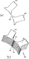
- the stator teeth 302 are formed as lamellae which are stacked in the axial direction of the stator 300. These fins can have at least two different shapes.
- Fig. 4 shows a first shape in the form of a stator star 305.
- the widened ends of the stator teeth 302 are each connected circumferentially via a connecting bridge 401.
- FIG. 5 A second form of these slats is in Fig. 5 shown, wherein the widened ends of the stator teeth 302 are not connected, but have an interruption 402. They are thus single teeth.
- these fins are arranged alternately stacked, such as Fig. 6 illustrated in an example in perspective.
- connection bridges 401 and interruptions 402 alternate.
- Other arrangements are possible, such as two or three slats with breaks 402 between two connecting bridges 401. Other combinations are of course conceivable.
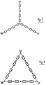
- FIGS. 7 and 8 show circuit diagrams of windings of the permanent magnet synchronous motor according to the invention, wherein both a conventional star connection after Fig. 7 as well as a delta connection Fig. 8 is possible.
- the delta connection offers the advantage here that only three connections U, V, W are required, one star connection or one star connection the star connection is omitted.
- FIG. 9 - 11 illustrate schematic plan views of three embodiments of a rotor 204 of the permanent magnet synchronous motor according to the invention Fig. 3 , Fig. 9 shows on the circumference of the rotor 204 in pockets arranged permanent magnets 203 with different polarity N, S in the axial direction of the rotor 204th Fig. 10 illustrates an arrangement of the permanent bearings 203 on the outer peripheral surface of the rotor 204, and Fig. 11 shows ring magnets on the outer peripheral surface of the rotor 204.
- a fourth embodiment of the rotor of the permanent magnet synchronous motor according to the invention Fig. 3 is in Fig. 12 shown in a schematic perspective view.
- the rotor 204 here consists of two rotor packages 205 which are arranged one behind the other in the axial direction and which are rotated by an offset angle ⁇ , which is preferably half the number of stator slots, about the axial direction relative to one another.
- an offset angle ⁇ which is preferably half the number of stator slots
- Fig. 14 is a graphical representation of a braking torque of the permanent magnet synchronous motor according to the invention according to Fig. 3 compared to a conventional permanent magnet synchronous motor over a speed. Torque values are plotted on the left ordinate and I phase on the right phase current values. The upper curve shown with a thick line is the normal braking torque of a conventional permanent magnet synchronous motor which has a maximum at a speed of 220 n -1 , whereas an optimized braking torque of the permanent magnet synchronous motor according to the invention has a maximum at 60 n -1 , which about 50% smaller than that of the conventional permanent magnet synchronous motor.
- the normal one Phase current I phase is plotted as a thin upper line, whereas the optimized phase current I phase of the permanent magnet synchronous motor according to the invention assumes a maximum value which is also smaller by about 50% than that of the conventional permanent magnet synchronous motor.
- the permanent magnet synchronous motor according to the invention with a lower braking torque provides greater safety to a conventional motor by blocking the steering in a possible fault, for example in a power steering, not by an excessive braking torque. Due to the lower power consumption of the permanent magnet synchronous motor according to the invention a lower energy consumption is possible.
- the use of the permanent magnet synchronous motor according to the invention in a power steering system of a motor vehicle can be carried out both on the steering gear 101, on the steering shaft 102, on the pinion 105 or elsewhere with corresponding couplings.
- stator teeth 302 it would also be conceivable for the stator teeth 302 to have connecting bridges 401 and interruptions 402 in a same slat plane in a third slat shape.
Landscapes
- Engineering & Computer Science (AREA)
- Power Engineering (AREA)
- Permanent Magnet Type Synchronous Machine (AREA)
- Iron Core Of Rotating Electric Machines (AREA)
- Permanent Field Magnets Of Synchronous Machinery (AREA)
- Power Steering Mechanism (AREA)
Claims (6)
- Moteur synchrone à aimants permanents, en particulier moteur électrique triphasé, comportant un rotor (204) doté d'aimants permanents (203), comportant un stator (300) doté d'une culasse de stator (301), dans laquelle des dents de stator (302) sont disposées avec des encoches de stator (202) entre elles,- au moins un enroulement (303) étant prévu respectivement sur une dent de stator (302),- les dents de stator (302) étant disposées empilées sous forme de lamelles dans la direction axiale du stator (300) et se présentant sous la forme d'au moins deux lamelles différentes,- les dents de stator (302) d'une première lamelle étant reliées entre elles de manière périphérique au niveau de leurs extrémités tournées vers le rotor (204) au moyen respectivement d'un pont de liaison (401) pour former une étoile statorique (305) et- les dents de stator (302) d'une deuxième lamelle présentant une interruption (402) au lieu du pont de liaison (401),- le rotor (204) présentant au moins deux paquets de tôles de rotor (205), qui sont disposés dans la direction axiale du rotor (204), les au moins deux paquets de tôles de rotor (205) étant disposés en décalage angulaire l'un par rapport à l'autre sur un axe de rotor selon un angle de décalage (γ), caractérisé en ce que- l'angle de décalage (γ) est, en degrés d'angle, inférieur ou égal à la moitié du nombre d'encoches de stator (202), l'angle de décalage (γ) se trouvant entre le premier et le dernier paquet de tôles de rotor (205) s'il y a plus de deux paquets de tôles de rotor (205),- les dents de stator (302) étant disposées sous la forme de lamelles dans la direction axiale du stator (300) dans l'ordre : étoile statorique (305) avec ponts de liaison (401), suivie d'une, deux ou trois lamelles respectivement dotées de dents de stator (302) non reliées en tant que dents individuelles,- les lamelles étant disposées, dans cette construction empilée, en alternance dans la direction axiale,- dans lequel- douze encoches de stator (202) et quatre paires de pôles de rotor ou- douze encoches de stator (202) et huit paires de pôles de rotor ou- douze encoches de stator (202) et dix paires de pôles de rotor ou- douze encoches de stator (202) et quatorze paires de pôles de rotor sont prévues.
- Moteur synchrone selon la revendication 1,
caractérisé en ce que
au moins une isolation (304) est prévue entre les enroulements (303) dans les encoches de stator (202). - Moteur synchrone selon l'une des revendications précédentes,
caractérisé en ce que
les enroulements (303) sont disposés en un couplage triphasé en étoile ou en un couplage triphasé en triangle. - Moteur synchrone selon l'une des revendications précédentes,
caractérisé en ce que
le rotor (204) présente des aimants permanents (203) dans des poches sur sa périphérie, sur sa surface de manière périphérique ou sous la forme d'aimants toriques. - Moteur synchrone selon l'une des revendications précédentes,
caractérisé en ce que
un nombre n de paquets de tôles de rotor (205) dépend d'une longueur axiale active (Lstk) du moteur synchrone à aimants permanents comme suit :n = 1 ou 2, lorsque Lstk ≤ 40 mmn = 2 ou 3, lorsque 40 ≤ Lstk ≤ 60 mmn = 3 ou 4, lorsque 60 ≤ Lstk ≤ 80 mmn = 4, lorsque 80 ≤ Lstk ≤ 130 mm - Servodirection électrique de véhicule à moteur,
qui présente un moteur synchrone à aimants permanents selon l'une des revendications précédentes.
Priority Applications (1)
| Application Number | Priority Date | Filing Date | Title |
|---|---|---|---|
| EP15198633.8A EP3038233B1 (fr) | 2008-09-15 | 2009-09-14 | Moteur synchrone a aimant permanent et direction assistee electrique |
Applications Claiming Priority (2)
| Application Number | Priority Date | Filing Date | Title |
|---|---|---|---|
| DE102008042100A DE102008042100A1 (de) | 2008-09-15 | 2008-09-15 | Permanentmagnet-Synchronmotor und elektrische Servolenkung |
| PCT/DE2009/001275 WO2010028639A1 (fr) | 2008-09-15 | 2009-09-14 | Moteur synchrone à aimant permanent et servodirection électrique |
Related Child Applications (2)
| Application Number | Title | Priority Date | Filing Date |
|---|---|---|---|
| EP15198633.8A Division EP3038233B1 (fr) | 2008-09-15 | 2009-09-14 | Moteur synchrone a aimant permanent et direction assistee electrique |
| EP15198633.8A Division-Into EP3038233B1 (fr) | 2008-09-15 | 2009-09-14 | Moteur synchrone a aimant permanent et direction assistee electrique |
Publications (2)
| Publication Number | Publication Date |
|---|---|
| EP2327136A1 EP2327136A1 (fr) | 2011-06-01 |
| EP2327136B1 true EP2327136B1 (fr) | 2016-08-17 |
Family
ID=41416029
Family Applications (2)
| Application Number | Title | Priority Date | Filing Date |
|---|---|---|---|
| EP09743837.8A Not-in-force EP2327136B1 (fr) | 2008-09-15 | 2009-09-14 | Moteur synchrone à aimant permanent et servodirection électrique |
| EP15198633.8A Not-in-force EP3038233B1 (fr) | 2008-09-15 | 2009-09-14 | Moteur synchrone a aimant permanent et direction assistee electrique |
Family Applications After (1)
| Application Number | Title | Priority Date | Filing Date |
|---|---|---|---|
| EP15198633.8A Not-in-force EP3038233B1 (fr) | 2008-09-15 | 2009-09-14 | Moteur synchrone a aimant permanent et direction assistee electrique |
Country Status (6)
| Country | Link |
|---|---|
| US (1) | US8614532B2 (fr) |
| EP (2) | EP2327136B1 (fr) |
| KR (1) | KR101485586B1 (fr) |
| CN (2) | CN102177638B (fr) |
| DE (1) | DE102008042100A1 (fr) |
| WO (1) | WO2010028639A1 (fr) |
Families Citing this family (15)
| Publication number | Priority date | Publication date | Assignee | Title |
|---|---|---|---|---|
| KR101313447B1 (ko) * | 2011-11-29 | 2013-10-01 | 엘지이노텍 주식회사 | 스테이터 코어 |
| EP2665156A1 (fr) * | 2012-05-14 | 2013-11-20 | Grundfos Holding A/S | Rotor pour un moteur électrique |
| DE102012213465A1 (de) * | 2012-07-31 | 2014-02-06 | Brose Fahrzeugteile GmbH & Co. Kommanditgesellschaft, Würzburg | Permanentmagnet-Synchronmotor und Servolenkungsanordnung |
| JP2014064395A (ja) * | 2012-09-21 | 2014-04-10 | Sanyo Denki Co Ltd | 埋め込み永久磁石型モータおよびロータ |
| US9214837B2 (en) | 2013-12-13 | 2015-12-15 | Arm Limited | Electric motor with plural stator components |
| NL2013403B1 (nl) * | 2014-09-02 | 2016-09-26 | Elsio Cicilia Beremundo | Synchrone rotatiemotor of generator voorzien van verscheidene rotors en/of stators. |
| DE102014222245A1 (de) | 2014-10-31 | 2016-05-04 | Brose Fahrzeugteile GmbH & Co. Kommanditgesellschaft, Würzburg | Statoranordnung für einen Elektromotor, Elektromotor sowie Verfahren zur Herstellung einer Statoranordnung |
| DE102016201967A1 (de) * | 2016-02-10 | 2017-08-10 | Robert Bosch Gmbh | Stator für eine elektrische Maschine, insbesondere für einen Innenäulfer-Elektromotor |
| CN106685113B (zh) * | 2017-02-28 | 2019-04-23 | 合肥工业大学 | 一种铸铝转子齿槽结构 |
| CN106602755A (zh) * | 2017-02-28 | 2017-04-26 | 合肥工业大学 | 一种可分离式定子电机 |
| JP6900846B2 (ja) * | 2017-09-05 | 2021-07-07 | 株式会社デンソー | ステータコア |
| CN109120080B (zh) * | 2018-09-19 | 2024-09-20 | 珠海格力电器股份有限公司 | 电机定子、电机和大巴 |
| CN114069912B (zh) * | 2021-12-17 | 2025-08-12 | 威灵(芜湖)电机制造有限公司 | 定子组件、电机和电器设备 |
| DE102022109794A1 (de) * | 2022-04-22 | 2023-10-26 | Dr. Ing. H.C. F. Porsche Aktiengesellschaft | Statoranordnung für eine Elektromaschine |
| WO2025251130A1 (fr) * | 2024-06-06 | 2025-12-11 | Melo Medeiros Antonio Roberto | Hypermoteur élastique multiplicateur de puissance |
Family Cites Families (13)
| Publication number | Priority date | Publication date | Assignee | Title |
|---|---|---|---|---|
| ITTO980343A1 (it) * | 1998-04-23 | 1999-10-23 | Bitron Spa | Motore elettrico a commutazione elettronica |
| DE19842948A1 (de) * | 1998-09-18 | 2000-03-30 | Siemens Ag | Elektromotor |
| US6597078B2 (en) * | 2000-12-04 | 2003-07-22 | Emerson Electric Co. | Electric power steering system including a permanent magnet motor |
| JP2003032936A (ja) * | 2001-07-16 | 2003-01-31 | Matsushita Electric Ind Co Ltd | 電動機 |
| DE10147073A1 (de) * | 2001-09-25 | 2003-04-30 | Minebea Co Ltd | Elektromotor, insbesondere elektronisch kommutierter Gleichstrommotor |
| US6822364B2 (en) * | 2002-07-30 | 2004-11-23 | Asmo Co., Ltd. | Brushless motor |
| JP4311182B2 (ja) * | 2003-12-08 | 2009-08-12 | 日産自動車株式会社 | 回転電機の回転子 |
| JP2006187130A (ja) * | 2004-12-28 | 2006-07-13 | Hitachi Ltd | 捲回式鉛電池を電源とする電動パワーステアリングシステム及びそれに用いられるモータとインバータ装置 |
| ITRE20050029A1 (it) * | 2005-03-24 | 2006-09-25 | Motor Power Co Srl | Motore elettrico trifase ad elevata coppia |
| JP4691376B2 (ja) * | 2005-03-25 | 2011-06-01 | 山洋電気株式会社 | 永久磁石型回転モータ |
| JP4476202B2 (ja) * | 2005-09-20 | 2010-06-09 | 山洋電気株式会社 | 永久磁石型回転モータ |
| JP4834386B2 (ja) | 2005-11-24 | 2011-12-14 | 株式会社東芝 | 永久磁石型モータ及びそれを使用した電動パワーステアリング装置 |
| JP2008228390A (ja) * | 2007-03-09 | 2008-09-25 | Jtekt Corp | ブラシレスモータおよびそれを備えた電動パワーステアリング装置 |
-
2008
- 2008-09-15 DE DE102008042100A patent/DE102008042100A1/de not_active Withdrawn
-
2009
- 2009-09-14 WO PCT/DE2009/001275 patent/WO2010028639A1/fr not_active Ceased
- 2009-09-14 US US13/119,013 patent/US8614532B2/en not_active Expired - Fee Related
- 2009-09-14 KR KR1020117006731A patent/KR101485586B1/ko not_active Expired - Fee Related
- 2009-09-14 CN CN200980140461.6A patent/CN102177638B/zh not_active Expired - Fee Related
- 2009-09-14 EP EP09743837.8A patent/EP2327136B1/fr not_active Not-in-force
- 2009-09-14 EP EP15198633.8A patent/EP3038233B1/fr not_active Not-in-force
- 2009-09-14 CN CN201510158399.0A patent/CN104868679B/zh not_active Expired - Fee Related
Non-Patent Citations (1)
| Title |
|---|
| NICOLA BIANCHI ET AL: "Design Techniques for Reducing the Cogging Torque in Surface-Mounted PM Motors", IEEE TRANSACTIONS ON INDUSTRY APPLICATIONS, IEEE SERVICE CENTER, PISCATAWAY, NJ, US, vol. 38, no. 5, 1 September 2002 (2002-09-01), XP011073515, ISSN: 0093-9994 * |
Also Published As
| Publication number | Publication date |
|---|---|
| CN104868679B (zh) | 2018-12-21 |
| DE102008042100A1 (de) | 2010-03-18 |
| EP3038233B1 (fr) | 2017-05-03 |
| KR101485586B1 (ko) | 2015-01-23 |
| EP2327136A1 (fr) | 2011-06-01 |
| US8614532B2 (en) | 2013-12-24 |
| CN102177638B (zh) | 2015-05-06 |
| CN102177638A (zh) | 2011-09-07 |
| WO2010028639A1 (fr) | 2010-03-18 |
| US20120098376A1 (en) | 2012-04-26 |
| EP3038233A1 (fr) | 2016-06-29 |
| CN104868679A (zh) | 2015-08-26 |
| KR20110069022A (ko) | 2011-06-22 |
Similar Documents
| Publication | Publication Date | Title |
|---|---|---|
| EP2327136B1 (fr) | Moteur synchrone à aimant permanent et servodirection électrique | |
| EP2427951B1 (fr) | Machine electrique synchrone | |
| EP2115857B1 (fr) | Moteur synchrone 18/8 | |
| EP2160816A2 (fr) | Moteur synchrone à 12 dents statoriques et 10 pôles rotoriques | |
| EP2483991A1 (fr) | Moteur synchrone sans balais | |
| EP3479462B1 (fr) | Système de machine électrique | |
| EP2991207A1 (fr) | Machine dynamoélectrique équipée de rotor à aimant permanent et à réluctance | |
| EP3352331A1 (fr) | Tôle de rotor pour un moteur électrique à excitation permanente et rotor | |
| DE102010032764A1 (de) | Elektrische Maschine und Stator für dieselbe | |
| EP2550721B1 (fr) | Machine électrique et dispositif de direction | |
| DE102016212022A1 (de) | Rotor | |
| WO2018002128A1 (fr) | Rotor, procédé de fabrication d'un rotor, machine à reluctance et machine de travail | |
| EP2517334B1 (fr) | Rotor pour un moteur électrique | |
| WO2015007441A2 (fr) | Machine électrique et ensemble de machines électriques | |
| EP2880750B1 (fr) | Moteur synchrone à aimants permanents et système de direction assistée | |
| EP2532073B1 (fr) | Stator de machine électrique rotative à excitation permanente | |
| EP2652862B1 (fr) | Élément de machine destiné à une machine électrique | |
| EP3035495A1 (fr) | Rotor pour une machine électrique à aimants permanents | |
| EP3035496B1 (fr) | Rotor pour une machine électrique à aimants permanents | |
| EP3900156B1 (fr) | Noyau feuilleté pour une machine électrique | |
| EP3472922B1 (fr) | Rotor pour une machine asynchrone électrique à cage d'écureuil surmoulée, machine électrique et procédé de fabrication | |
| DE102015105991B4 (de) | Elektroarbeitsmaschine hoher Leistungsdichte | |
| EP2532074B1 (fr) | Stator pour une machine électrique tournante à aimants permanents | |
| WO2024067918A1 (fr) | Rotor et machine électrique | |
| DE102013207017A1 (de) | Verbessertes Blechpaket eines Läufers mit großem Durchmesser |
Legal Events
| Date | Code | Title | Description |
|---|---|---|---|
| PUAI | Public reference made under article 153(3) epc to a published international application that has entered the european phase |
Free format text: ORIGINAL CODE: 0009012 |
|
| 17P | Request for examination filed |
Effective date: 20110314 |
|
| AK | Designated contracting states |
Kind code of ref document: A1 Designated state(s): AT BE BG CH CY CZ DE DK EE ES FI FR GB GR HR HU IE IS IT LI LT LU LV MC MK MT NL NO PL PT RO SE SI SK SM TR |
|
| AX | Request for extension of the european patent |
Extension state: AL BA RS |
|
| RIN1 | Information on inventor provided before grant (corrected) |
Inventor name: JUNAK, JACEK Inventor name: STEEGMUELLER, HORST Inventor name: OMBACH, GRZEGORZ |
|
| DAX | Request for extension of the european patent (deleted) | ||
| 17Q | First examination report despatched |
Effective date: 20140305 |
|
| GRAP | Despatch of communication of intention to grant a patent |
Free format text: ORIGINAL CODE: EPIDOSNIGR1 |
|
| INTG | Intention to grant announced |
Effective date: 20160316 |
|
| GRAS | Grant fee paid |
Free format text: ORIGINAL CODE: EPIDOSNIGR3 |
|
| GRAA | (expected) grant |
Free format text: ORIGINAL CODE: 0009210 |
|
| AK | Designated contracting states |
Kind code of ref document: B1 Designated state(s): AT BE BG CH CY CZ DE DK EE ES FI FR GB GR HR HU IE IS IT LI LT LU LV MC MK MT NL NO PL PT RO SE SI SK SM TR |
|
| REG | Reference to a national code |
Ref country code: GB Ref legal event code: FG4D Free format text: NOT ENGLISH |
|
| REG | Reference to a national code |
Ref country code: FR Ref legal event code: PLFP Year of fee payment: 8 |
|
| REG | Reference to a national code |
Ref country code: CH Ref legal event code: EP |
|
| REG | Reference to a national code |
Ref country code: IE Ref legal event code: FG4D Free format text: LANGUAGE OF EP DOCUMENT: GERMAN |
|
| REG | Reference to a national code |
Ref country code: AT Ref legal event code: REF Ref document number: 821892 Country of ref document: AT Kind code of ref document: T Effective date: 20160915 |
|
| REG | Reference to a national code |
Ref country code: DE Ref legal event code: R096 Ref document number: 502009012972 Country of ref document: DE |
|
| REG | Reference to a national code |
Ref country code: NL Ref legal event code: MP Effective date: 20160817 |
|
| REG | Reference to a national code |
Ref country code: LT Ref legal event code: MG4D |
|
| PG25 | Lapsed in a contracting state [announced via postgrant information from national office to epo] |
Ref country code: IT Free format text: LAPSE BECAUSE OF FAILURE TO SUBMIT A TRANSLATION OF THE DESCRIPTION OR TO PAY THE FEE WITHIN THE PRESCRIBED TIME-LIMIT Effective date: 20160817 Ref country code: NL Free format text: LAPSE BECAUSE OF FAILURE TO SUBMIT A TRANSLATION OF THE DESCRIPTION OR TO PAY THE FEE WITHIN THE PRESCRIBED TIME-LIMIT Effective date: 20160817 Ref country code: FI Free format text: LAPSE BECAUSE OF FAILURE TO SUBMIT A TRANSLATION OF THE DESCRIPTION OR TO PAY THE FEE WITHIN THE PRESCRIBED TIME-LIMIT Effective date: 20160817 Ref country code: NO Free format text: LAPSE BECAUSE OF FAILURE TO SUBMIT A TRANSLATION OF THE DESCRIPTION OR TO PAY THE FEE WITHIN THE PRESCRIBED TIME-LIMIT Effective date: 20161117 Ref country code: HR Free format text: LAPSE BECAUSE OF FAILURE TO SUBMIT A TRANSLATION OF THE DESCRIPTION OR TO PAY THE FEE WITHIN THE PRESCRIBED TIME-LIMIT Effective date: 20160817 Ref country code: LT Free format text: LAPSE BECAUSE OF FAILURE TO SUBMIT A TRANSLATION OF THE DESCRIPTION OR TO PAY THE FEE WITHIN THE PRESCRIBED TIME-LIMIT Effective date: 20160817 |
|
| PG25 | Lapsed in a contracting state [announced via postgrant information from national office to epo] |
Ref country code: PL Free format text: LAPSE BECAUSE OF FAILURE TO SUBMIT A TRANSLATION OF THE DESCRIPTION OR TO PAY THE FEE WITHIN THE PRESCRIBED TIME-LIMIT Effective date: 20160817 Ref country code: BE Free format text: LAPSE BECAUSE OF NON-PAYMENT OF DUE FEES Effective date: 20160930 Ref country code: ES Free format text: LAPSE BECAUSE OF FAILURE TO SUBMIT A TRANSLATION OF THE DESCRIPTION OR TO PAY THE FEE WITHIN THE PRESCRIBED TIME-LIMIT Effective date: 20160817 Ref country code: SE Free format text: LAPSE BECAUSE OF FAILURE TO SUBMIT A TRANSLATION OF THE DESCRIPTION OR TO PAY THE FEE WITHIN THE PRESCRIBED TIME-LIMIT Effective date: 20160817 Ref country code: LV Free format text: LAPSE BECAUSE OF FAILURE TO SUBMIT A TRANSLATION OF THE DESCRIPTION OR TO PAY THE FEE WITHIN THE PRESCRIBED TIME-LIMIT Effective date: 20160817 Ref country code: GR Free format text: LAPSE BECAUSE OF FAILURE TO SUBMIT A TRANSLATION OF THE DESCRIPTION OR TO PAY THE FEE WITHIN THE PRESCRIBED TIME-LIMIT Effective date: 20161118 Ref country code: PT Free format text: LAPSE BECAUSE OF FAILURE TO SUBMIT A TRANSLATION OF THE DESCRIPTION OR TO PAY THE FEE WITHIN THE PRESCRIBED TIME-LIMIT Effective date: 20161219 |
|
| PG25 | Lapsed in a contracting state [announced via postgrant information from national office to epo] |
Ref country code: EE Free format text: LAPSE BECAUSE OF FAILURE TO SUBMIT A TRANSLATION OF THE DESCRIPTION OR TO PAY THE FEE WITHIN THE PRESCRIBED TIME-LIMIT Effective date: 20160817 Ref country code: RO Free format text: LAPSE BECAUSE OF FAILURE TO SUBMIT A TRANSLATION OF THE DESCRIPTION OR TO PAY THE FEE WITHIN THE PRESCRIBED TIME-LIMIT Effective date: 20160817 |
|
| REG | Reference to a national code |
Ref country code: CH Ref legal event code: PL |
|
| REG | Reference to a national code |
Ref country code: DE Ref legal event code: R097 Ref document number: 502009012972 Country of ref document: DE |
|
| PG25 | Lapsed in a contracting state [announced via postgrant information from national office to epo] |
Ref country code: CZ Free format text: LAPSE BECAUSE OF FAILURE TO SUBMIT A TRANSLATION OF THE DESCRIPTION OR TO PAY THE FEE WITHIN THE PRESCRIBED TIME-LIMIT Effective date: 20160817 Ref country code: SK Free format text: LAPSE BECAUSE OF FAILURE TO SUBMIT A TRANSLATION OF THE DESCRIPTION OR TO PAY THE FEE WITHIN THE PRESCRIBED TIME-LIMIT Effective date: 20160817 Ref country code: BG Free format text: LAPSE BECAUSE OF FAILURE TO SUBMIT A TRANSLATION OF THE DESCRIPTION OR TO PAY THE FEE WITHIN THE PRESCRIBED TIME-LIMIT Effective date: 20161117 Ref country code: SM Free format text: LAPSE BECAUSE OF FAILURE TO SUBMIT A TRANSLATION OF THE DESCRIPTION OR TO PAY THE FEE WITHIN THE PRESCRIBED TIME-LIMIT Effective date: 20160817 Ref country code: DK Free format text: LAPSE BECAUSE OF FAILURE TO SUBMIT A TRANSLATION OF THE DESCRIPTION OR TO PAY THE FEE WITHIN THE PRESCRIBED TIME-LIMIT Effective date: 20160817 |
|
| PLBE | No opposition filed within time limit |
Free format text: ORIGINAL CODE: 0009261 |
|
| STAA | Information on the status of an ep patent application or granted ep patent |
Free format text: STATUS: NO OPPOSITION FILED WITHIN TIME LIMIT |
|
| REG | Reference to a national code |
Ref country code: IE Ref legal event code: MM4A |
|
| PG25 | Lapsed in a contracting state [announced via postgrant information from national office to epo] |
Ref country code: MC Free format text: LAPSE BECAUSE OF FAILURE TO SUBMIT A TRANSLATION OF THE DESCRIPTION OR TO PAY THE FEE WITHIN THE PRESCRIBED TIME-LIMIT Effective date: 20160817 |
|
| 26N | No opposition filed |
Effective date: 20170518 |
|
| GBPC | Gb: european patent ceased through non-payment of renewal fee |
Effective date: 20161117 |
|
| PG25 | Lapsed in a contracting state [announced via postgrant information from national office to epo] |
Ref country code: IE Free format text: LAPSE BECAUSE OF NON-PAYMENT OF DUE FEES Effective date: 20160914 Ref country code: LI Free format text: LAPSE BECAUSE OF NON-PAYMENT OF DUE FEES Effective date: 20160930 Ref country code: CH Free format text: LAPSE BECAUSE OF NON-PAYMENT OF DUE FEES Effective date: 20160930 |
|
| REG | Reference to a national code |
Ref country code: FR Ref legal event code: PLFP Year of fee payment: 9 |
|
| PG25 | Lapsed in a contracting state [announced via postgrant information from national office to epo] |
Ref country code: LU Free format text: LAPSE BECAUSE OF NON-PAYMENT OF DUE FEES Effective date: 20160914 Ref country code: SI Free format text: LAPSE BECAUSE OF FAILURE TO SUBMIT A TRANSLATION OF THE DESCRIPTION OR TO PAY THE FEE WITHIN THE PRESCRIBED TIME-LIMIT Effective date: 20160817 |
|
| REG | Reference to a national code |
Ref country code: AT Ref legal event code: MM01 Ref document number: 821892 Country of ref document: AT Kind code of ref document: T Effective date: 20160914 |
|
| REG | Reference to a national code |
Ref country code: BE Ref legal event code: MM Effective date: 20160930 |
|
| PG25 | Lapsed in a contracting state [announced via postgrant information from national office to epo] |
Ref country code: GB Free format text: LAPSE BECAUSE OF NON-PAYMENT OF DUE FEES Effective date: 20161117 |
|
| PG25 | Lapsed in a contracting state [announced via postgrant information from national office to epo] |
Ref country code: AT Free format text: LAPSE BECAUSE OF NON-PAYMENT OF DUE FEES Effective date: 20160914 |
|
| PG25 | Lapsed in a contracting state [announced via postgrant information from national office to epo] |
Ref country code: HU Free format text: LAPSE BECAUSE OF FAILURE TO SUBMIT A TRANSLATION OF THE DESCRIPTION OR TO PAY THE FEE WITHIN THE PRESCRIBED TIME-LIMIT; INVALID AB INITIO Effective date: 20090914 Ref country code: CY Free format text: LAPSE BECAUSE OF FAILURE TO SUBMIT A TRANSLATION OF THE DESCRIPTION OR TO PAY THE FEE WITHIN THE PRESCRIBED TIME-LIMIT Effective date: 20160817 |
|
| PG25 | Lapsed in a contracting state [announced via postgrant information from national office to epo] |
Ref country code: MK Free format text: LAPSE BECAUSE OF FAILURE TO SUBMIT A TRANSLATION OF THE DESCRIPTION OR TO PAY THE FEE WITHIN THE PRESCRIBED TIME-LIMIT Effective date: 20160817 Ref country code: TR Free format text: LAPSE BECAUSE OF FAILURE TO SUBMIT A TRANSLATION OF THE DESCRIPTION OR TO PAY THE FEE WITHIN THE PRESCRIBED TIME-LIMIT Effective date: 20160817 Ref country code: MT Free format text: LAPSE BECAUSE OF FAILURE TO SUBMIT A TRANSLATION OF THE DESCRIPTION OR TO PAY THE FEE WITHIN THE PRESCRIBED TIME-LIMIT Effective date: 20160817 Ref country code: IS Free format text: LAPSE BECAUSE OF FAILURE TO SUBMIT A TRANSLATION OF THE DESCRIPTION OR TO PAY THE FEE WITHIN THE PRESCRIBED TIME-LIMIT Effective date: 20160817 |
|
| REG | Reference to a national code |
Ref country code: FR Ref legal event code: PLFP Year of fee payment: 10 |
|
| REG | Reference to a national code |
Ref country code: DE Ref legal event code: R081 Ref document number: 502009012972 Country of ref document: DE Owner name: BROSE FAHRZEUGTEILE SE & CO. KOMMANDITGESELLSC, DE Free format text: FORMER OWNER: BROSE FAHRZEUGTEILE GMBH & CO. KOMMANDITGESELLSCHAFT, WUERZBURG, 97076 WUERZBURG, DE |
|
| REG | Reference to a national code |
Ref country code: FR Ref legal event code: PLFP Year of fee payment: 13 |
|
| PGFP | Annual fee paid to national office [announced via postgrant information from national office to epo] |
Ref country code: FR Payment date: 20210812 Year of fee payment: 13 |
|
| PGFP | Annual fee paid to national office [announced via postgrant information from national office to epo] |
Ref country code: DE Payment date: 20210930 Year of fee payment: 13 |
|
| REG | Reference to a national code |
Ref country code: DE Ref legal event code: R119 Ref document number: 502009012972 Country of ref document: DE |
|
| PG25 | Lapsed in a contracting state [announced via postgrant information from national office to epo] |
Ref country code: FR Free format text: LAPSE BECAUSE OF NON-PAYMENT OF DUE FEES Effective date: 20220930 Ref country code: DE Free format text: LAPSE BECAUSE OF NON-PAYMENT OF DUE FEES Effective date: 20230401 |