EP2327140B1 - Sechspolige gleichstrommaschine - Google Patents
Sechspolige gleichstrommaschine Download PDFInfo
- Publication number
- EP2327140B1 EP2327140B1 EP09780746.5A EP09780746A EP2327140B1 EP 2327140 B1 EP2327140 B1 EP 2327140B1 EP 09780746 A EP09780746 A EP 09780746A EP 2327140 B1 EP2327140 B1 EP 2327140B1
- Authority
- EP
- European Patent Office
- Prior art keywords
- brushes
- commutator
- brush holder
- brush
- sector
- Prior art date
- Legal status (The legal status is an assumption and is not a legal conclusion. Google has not performed a legal analysis and makes no representation as to the accuracy of the status listed.)
- Not-in-force
Links
- 230000001629 suppression Effects 0.000 claims description 14
- 238000004804 winding Methods 0.000 claims description 10
- 239000003990 capacitor Substances 0.000 claims description 4
- 230000005284 excitation Effects 0.000 claims description 4
- 244000185238 Lophostemon confertus Species 0.000 claims 2
- 238000000926 separation method Methods 0.000 claims 1
- XEEYBQQBJWHFJM-UHFFFAOYSA-N Iron Chemical compound [Fe] XEEYBQQBJWHFJM-UHFFFAOYSA-N 0.000 description 2
- 238000004519 manufacturing process Methods 0.000 description 2
- 230000001680 brushing effect Effects 0.000 description 1
- 238000001816 cooling Methods 0.000 description 1
- 238000009434 installation Methods 0.000 description 1
- 229910052742 iron Inorganic materials 0.000 description 1
- 238000000034 method Methods 0.000 description 1
- 239000002991 molded plastic Substances 0.000 description 1
- 239000007858 starting material Substances 0.000 description 1
Images



Classifications
-
- H—ELECTRICITY
- H02—GENERATION; CONVERSION OR DISTRIBUTION OF ELECTRIC POWER
- H02K—DYNAMO-ELECTRIC MACHINES
- H02K13/00—Structural associations of current collectors with motors or generators, e.g. brush mounting plates or connections to windings; Disposition of current collectors in motors or generators; Arrangements for improving commutation
- H02K13/10—Arrangements of brushes or commutators specially adapted for improving commutation
Definitions
- the invention relates to a six-pole DC machine, in particular of a six-pole DC motor for use in a motor vehicle, which has a preferably permanent magnetically excited stator and a rotatably mounted in a pole housing rotor with a wave winding.
- Such machines are basically known, for example in the application as starter motors for motor vehicles.
- WO 2008/062791 A1 is a six-pole DC motor has become known in which brushes are arranged on a brush holder, which electrically contact a commutator. In this example, two brushes are arranged at an angular distance of 60 °, wherein the commutator has nine commutator bars.
- the WO 2007/104589 A1 also shows an electric machine, in which, for example, a commutator has ten fins, and two brushes are arranged at an angular distance of 180 °.
- an electric dynamo is shown in which, for example, four brushes are arranged at an angular distance of 60 ° to each other on a brush holder.
- the US 2,645,731 A shows an electric generator having a commutator, abut the six brushes at different angular distances from each other.
- the six-pole DC machine according to the invention with the features of the independent claim has the advantage that in principle already reduced size of the machine by the six-pole design while reducing the brush apparatus, the cost of the machine can be reduced, with the ripple of the motor current through the special arrangement of brushes and the torque ripple and the resulting noise excitations and electromagnetic interference are significantly reduced while increasing the service life of the machine.
- the commutator of the machine has an even number of lamellae, which in particular corresponds to twice the number of rotor slots.
- the brush holder in a sector of approximately 180 ° on four brackets for receiving brush bags, the application depending optionally be equipped with two, three or four brushes.
- the brush holder brushing the current load of each size and so the variety of parts for the manufacture of machines can be reduced.
- all brushes are arranged in a first sector of the brush holder and required electrical interference suppression outside of this sector, the already suppressed electrical connections outside the sector of the brush holder occupied by the brushes and so a re-interference of interference in the already suppressed power is avoided ,
- the rotor With regard to the design of the rotor, it is advantageous if it is formed with ten individual teeth 21 and the rotor winding is designed as a single tooth winding. This gives a good utilization of the rotary iron and an improvement in the efficiency of the machine.
- FIG. 1 is denoted by 10 a six-pole DC machine in the embodiment as a drive motor for the cooling fan of a motor vehicle.
- the machine has a cup-shaped pole housing 12, which is closed on one side by a bearing cap 14.
- a stator 16 is formed by six permanent magnets 18 which are fixed to the pole housing 12 in a known manner.
- a rotor 20 of the machine with individual teeth 21 is seated on a shaft 22 which is rotatably mounted on the one hand in the pole housing 12 and on the other hand in the bearing cap 14.
- a commutator 24 with slats 25 and slots 27 is further arranged, which is supplied via brushes 26, the excitation current for the single-tooth coils of a wave winding 23.
- the brushes 26 and other components, in particular the required interference suppression of the machine are held on a brush holder 28.
- the suppression means of the engine are in FIG. 1 one of two suppression chokes 30,31 and a capacitor 32 to recognize.
- the locking of the brush holder 28 in the pole housing 12 is effected by a mounting flange 34 which extends over the entire circumference of the brush holder and is clamped between the pole housing 12 and the bearing cap 14 in the fully assembled state of the machine.
- a mounting flange 34 which extends over the entire circumference of the brush holder and is clamped between the pole housing 12 and the bearing cap 14 in the fully assembled state of the machine.
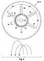
- FIGS. 2 to 4 show in schematic representations of the brush holder 28 of the DC machine according to the invention with the brushes 26 and the commutator 24.
- the brushes 26 are arranged at a tolerance of +/- 5 ° with an angular distance of approximately 60 ° to each other.
- the power supply to the commutator 24 takes place in FIG. 2 over two brushes, in FIG. 3 over three brushes and in FIG. 4 over four brushes.
- the brushes 26 each have a width b which is slightly narrower than the surface width of the commutator bars 1 to 20. All three embodiments have the same number of twenty commutator bars 25 at ten rotor teeth 21.
- the number of brushes is smaller than that of a six-pole DC machine with Wave winding when fully equipped existing number of six brushes, but the current ripple and the resulting torque ripple and the resulting noise excitations are significantly lower than in known equipping a six-pole machine with two or four brushes which are diametrically opposed to each other on the commutator.
- the current flow in the rotor coils is also schematized in the illustrations to the right of the brush arrangements of Figures 2 . 3 and 4 shown. From the Kurveriverlauf it can be seen that in the arrangement according to FIG. 2 with two at an angle of 60 ° to each other arranged brushes in the region of a fin pitch of 18 ° only two Kominutleiteren done while using three or four brushes in the Figures 3 and 4 In this range, three commutations take place, in each case at a distance of 6 ° to the commutator. The missing half-wave of a current at the arrangement in accordance with FIG. 2 is indicated by a dashed line.
- three or four brushes 26 are each arranged at an angular distance of approximately 60 ° to each other, which at the periphery of the commutator 24 three different positions to the commutator slots assume, so that in the region of a fin pitch three commutation are with a further improved reduction of current ripple over the embodiment accordingly FIG. 2 ,
- the current load in the brushes 26 is halved, which increases the service life of the brushes.
- FIGS. 2 to 4 clearly the reduction of the space requirement for the brush 26, whereby space for the arrangement of suppression components 30, 31, 32 is provided on the brush holder 26.
- FIG. 5 shows a plan view of the molded plastic brush holder 28.
- the connection line 36 is connected to one electrode and the connection line 38 to the other electrode of the interference suppression capacitor 32. From the illustration in FIG FIG. 5 the arrangement of the suppression components 30, 31 and 32 on the brush holder 28 can be seen.
- the brush holder quiver holders 56 are arranged on the base plate 54 such that the brushes 26 are in a first sector extending approximately over the upper half of the base plate 54 and the electrical interference suppression means 30, 31, 32 in a second sector on the lower half the base plate 54 lie.
- the suppressed electrical connections to the chokes 30 and 31 and to the capacitor 32 outside of the brush 26th taken upper sector of the brush holder 28 and the longitudinal axes of the brushes do not intersect with the electrical connections, which lie between the electrical connection lines 36, 38 and the suppression chokes 30, 31.
- EMC electromagnetic compatibility
Landscapes
- Engineering & Computer Science (AREA)
- Power Engineering (AREA)
- Dc Machiner (AREA)
- Motor Or Generator Current Collectors (AREA)
- Motor Or Generator Frames (AREA)
Description
- Die Erfindung geht aus von einer sechspoligen Gleichstrommaschine, insbesondere von einem sechspoligen Gleichstrommotor für den Einsatz in einem Kraftfahrzeug, welche einen vorzugsweise permanentmagnetisch erregten Stator und einen drehbar in einem Polgehäuse gelagerten Rotor mit einer Wellenwicklung aufweist. Derartige Maschinen sind grundsätzlich bekannt, beispielsweise in der Anwendung als Startermotoren für Kraftfahrzeuge.
- Weiterhin ist aus der Patentanmeldung
EP 0359603 A eine sechspolige Gleichstrommaschine mit einer über vier Bürsten gespeisten Rotorwicklung bekannt, deren gleichpolige Bürsten unter einem Winkel von vorzugsweise 120° angeordnet sind, während die Bürsten mit unterschiedlichen Potentialen einen Winkel von vorzugsweise 60° einschleißen. Hierbei liegen jeweils zwei Bürsten am Kommutator diametral gegenüber, so dass sich trotz einer Anordnung von vier Bürsten nur zwei Kommututierungszeitpunkte für die Rotorwicklung ergeben. - Mit der
WO 2008/062791 A1 ist ein sechspoliger DC-Motor bekannt geworden, bei dem auf einen Bürstenträger Bürsten angeordnet sind, die einen Kommutator elektrisch kontaktieren. Dabei sind beispielsweise zwei Bürsten in einem Winkelabstand von 60° angeordnet, wobei der Kommutator neun Kommutatorlamellen aufweist. DieWO 2007/104589 A1 zeigt ebenfalls eine elektrische Maschine, bei der beispielsweise ein Kommutator zehn Lamellen aufweist, und zwei Bürsten in einem Winkelabstand von 180° angeordnet sind. In derUS 3,648,090 A ist ein elektrischer Dynamo dargestellt, bei dem beispielsweise vier Bürsten in einem Winkelabstand von 60° zueinander auf einem Bürstenhalter angeordnet sind. DieUS 2,645,731 A zeigt einen elektrischen Generator der einen Kommutator aufweist, an dem sechs Bürsten mit unterschiedlichen Winkelabständen zueinander anliegen. - Die erfindungsgemäße sechspolige Gleichstrommaschine mit den Merkmalen des unabhängigen Anspruchs hat den Vorteil, dass bei grundsätzlich bereits reduzierter Baugröße der Maschine durch die sechspolige Ausführung bei gleichzeitiger Verkleinerung des Bürstenapparates die Kosten der Maschine reduziert werden können, wobei durch die spezielle Anordnung der Bürsten die Welligkeit des Motorstromes und die Momentenwelligkeit sowie die hierdurch erzeugten Geräuschanregungen und elektromagnetischen Störungen deutlich verringert werden bei gleichzeitiger Standzeiterhöhung der Maschine.
- Besonders vorteilhaft ist es, wenn der Kommutator der Maschine eine gerade Anzahl von Lamellen aufweist, welche insbesondere der doppelten Anzahl der Rotornuten entspricht.
- Durch die Reduzierung der Bürstenzahl auf eine Anordnung mit nur zwei Bürsten erhält man dabei den größten Vorteil hinsichtlich der Fertigungskosten und der Einsparung von Bauraum. Mit einer erfindungsgemäßen Anordnung von drei oder vier Bürsten und der hierdurch erreichten Erhöhung der Kommutierungszeitpunkte des Rotorstromes auf drei kann mit verhältnismäßig geringem Mehraufwand bei ebenfalls gegenüber einer Vollbestückung der Bürstenanordnung deutlich reduzierten Kosten und verringertem Platzbedarf die Welligkeit des Motorstromes noch weiter reduziert und näherungsweise der geringstmöglichen Welligkeit des Motorstromes bei einer Bestückung mit sechs Bürsten angeglichen werden. Die Verringerung der Bürstenzahl und deren Querschnitt muss jeweils der Strombelastung der Bürsten Rechnung tragen.
- Erfindungsgemäß weist der Bürstenträger in einem Sektor von cirka 180° vier Halterungen für die Aufnahme von Bürstenköchern auf, die applikationsabhängig wahlweise mit zwei, drei oder vier Bürsten bestückbar sind. Hierdurch kann mit einer einzigen Ausführungsform des Bürstenträgers die Bürstenbestückung der Strombelastung der jeweiligen Baugröße angepasst und so die Teilevielfalt für die Herstellung der Maschinen reduziert werden. Vorzugsweise sind dabei alle Bürsten in einem ersten Sektor des Bürstenträgers und erforderliche elektrische Entstörmittel außerhalb dieses Sektors angeordnet, wobei die bereits entstörten elektrischen Verbindungen außerhalb des von den Bürsten eingenommenen Sektors des Bürstenträgers verlaufen und so eine erneute Einstreuung von Störungen in die bereits entstörten Leistungen vermieden wird.
- Hinsichtlich der Gestaltung der Rotors ist es vorteilhaft, wenn dieser mit zehn Einzelzähnen 21 ausgebildet und die Rotorwicklung als Einzelzahnwicklung ausgeführt wird. Hierdurch erhält man eine gute Ausnutzung des Rotoreisen und eine Wirkungsgradverbesserung der Maschine.
- Weitere Einzelheiten und Ausgestaltungen der Erfindung ergeben sich aus den Patentansprüchen und der Beschreibung der Ausführungsbeispiele der Erfindung.
- Ausführungsbeispiele der Erfindung sind in den Zeichnungen dargestellt und in der nachfolgenden Beschreibung näher erläutert.
- Es zeigen:
- Figur 1
- eine Schnittdarstellung der erfindungsgemäßen Gleichstrommaschine,
- Figur 2
- eine schematisierte Darstellung eines über zwei Bürsten bestromten Rotors mit den zugehörigen Stromkennlinien,
- Figur 3
- eine schematisierte Darstellung eines über drei Bürsten bestromten Rotors mit den zugehörigen Stromkennlinien,
- Figur 4
- eine schematisierte Darstellung eines über vier Bürsten bestromten Rotors mit den zugehörigen Stromkennlinien und
- Figur 5
- eine Ansicht eines mit drei Bürsten und Entstörkomponenten bestückten Bürstenträgers der erfindungsgemäßen Maschine.
- In
Figur 1 ist mit 10 eine sechspolige Gleichstrommaschine bezeichnet in der Ausführung als Antriebsmotor für das Kühlgebläse eines Kraftfahrzeuges. Die Maschine besitzt ein topfförmiges Polgehäuse 12, welches durch einen Lagerdeckel 14 einseitig geschlossen ist. Innerhalb des Polgehäuses 12 wird ein Stator 16 durch sechs Permanentmagnete 18 ausgebildet, welche am Polgehäuse 12 in bekannter Weise befestigt sind. Ein Rotor 20 der Maschine mit Einzelzähnen 21 sitzt auf einer Welle 22, welche einerseits im Polgehäuse 12 und andererseits im Lagerdeckel 14 drehbar gelagert ist. - Auf der Rotorwelle 22 ist weiterhin ein Kommutator 24 mit Lamellen 25 und Schlitzen 27 angeordnet, welchem über Bürsten 26 der Erregerstrom für die Einzelzahnspulen einer Wellenwicklung 23 zugeführt wird.
- Die Bürsten 26 und weitere Komponenten, insbesondere die erforderlichen Entstörmittel der Maschine, sind auf einem Bürstenträger 28 gehalten. Von den Entstörmitteln des Motors sind in
Figur 1 eine von zwei Entstördrosseln 30,31 und ein Kondensator 32 zu erkennen. Die Arretierung des Bürstenträgers 28 im Polgehäuse 12 erfolgt durch einen Befestigungsflansch 34, welcher sich über den gesamten Umfang des Bürstenträgers erstreckt und zwischen dem Polgehäuse 12 und dem Lagerdeckel 14 im fertig montierten Zustand der Maschine eingeklemmt ist. Im Einzelnen wird der Aufbau des Bürstenträgers 28 und die Anordnung der Bürsten an Hand der folgenden Figuren erläutert, in denen für gleiche Teile gleiche Bezugszeichen verwendet sind. - Die
Figuren 2 bis 4 zeigen in schematisierten Darstellungen den Bürstenträger 28 der erfindungsgemäßen Gleichstrommaschine mit den Bürsten 26 und dem Kommutator 24. In allen drei Ausführungsformen sind die Bürsten 26 bei einer Toleranz von +/-5° mit einem Winkelabstand von jeweils cirka 60° zueinander angeordnet. Die Stromzuführung zum Kommutator 24 erfolgt inFigur 2 über zwei Bürsten, inFigur 3 über drei Bürsten und inFigur 4 über vier Bürsten. Die Bürsten 26 haben jeweils eine Breite b, die geringfügig schmäler ist als die Oberflächenbreite der Kommutatorlamellen 1 bis 20. Alle drei Ausführungsformen haben die gleiche Anzahl von jeweils zwanzig Kommutatorlamellen 25 bei zehn Rotorzähnen 21. Erfindungsgemäß ist die Bürstenzahl jeweils kleiner als die bei einer sechspoligen Gleichstrommaschine mit Wellenwicklung bei Vollbestückung vorhandene Anzahl von sechs Bürsten, wobei jedoch die Stromwelligkeit sowie die hierdurch bedingte Momentenwelligkeit und die entstehenden Geräuschanregungen deutlich geringer sind als bei bekannten Bestückungen einer sechspoligen Maschine mit zwei oder vier Bürsten, welche einander am Kommutator diametral gegenüber liegen. - Der Stromverlauf in den Rotorspulen ist ebenfalls schematisiert in den Darstellungen rechts neben den Bürstenanordnungen der
Figuren 2 ,3 und4 dargestellt. Aus dem Kurveriverlauf ist ersichtlich, dass bei der Anordnung gemäßFigur 2 mit zwei unter einem Winkel von 60° zueinander angeordneten Bürsten im Bereich einer Lamellenteilung von 18° nur zwei Kominutierungen erfolgen, während bei der Verwendung von drei oder vier Bürsten in denFiguren 3 und4 in diesem Bereich drei Kommutierungen stattfinden, und zwar in einem Abstand von jeweils 6° am Kommutatorumfang. Die fehlende Halbwelle des Stromes bei der Anordnung gemäßFigur 2 ist durch eine gestrichelte Linie angedeutet. Im Gegensatz zu zwei diametral gegenüber liegenden Bürsten mit gleicher Positionierung zu den Kommutatorschlitzen 27 erfolgen hierbei jedoch zwei Kommutierungen anstelle einer einzigen Kommutierung im Bereich einer Lamellenteilung, weshalb die resultierende Stromwelligkeit gegenüber der bekannten diametralen Anordnung von zwei Bürsten mit einem Kommutierungszeitpunkt pro Lamellenteilung deutlich geringer ist. - Bei den erfindungsgemäßen Anordnungen entsprechend den
Figuren 3 und4 sind drei, beziehungsweise vier Bürsten 26 jeweils in einem Winkelabstand von cirka 60° zueinander angeordnet, welche am Umfang des Kommutators 24 drei unterschiedliche Positionen zu den Kommutatorschlitzen einnehmen, sodass im Bereich einer Lamellenteilung drei Kommutierungszeitpunkte liegen mit einer nochmals verbesserten Reduzierung der Stromwelligkeit gegenüber der Ausführungsform entsprechendFigur 2 . Zusätzlich ist bei der Anordnung mit vier Bürsten entsprechendFigur 4 im Bereich eines Kommutierungsvorganges die Strombelastung in den Bürsten 26 jeweils halbiert, wodurch sich die Standzeit der Bürsten erhöht. - Weiterhin zeigen die Darstellungen in den
Figuren 2 bis 4 deutlich die Reduzierung des Platzbedarfes für die Bürsten 26, wodurch Platz für die Anordnung von Entstörkomponenten 30, 31, 32 auf dem Bürstenträger 26 geschaffen wird. -
Figur 5 zeigt eine Draufsicht auf den aus Kunststoff gespritzten Bürstenträger 28. Die Stromzufuhr von einer nicht dargestellten Gleichspannungsquelle erfolgt über zwei Anschlussleitungen 36 und 38, welche einerseits mit dem positiven und andererseits mit dem negativen Pol der Gleichspannungsquelle sowie mit den Entstördrosseln 30 und 31 verbunden sind. Gleichzeitig liegt die Anschlussleitung 36 an einer Elektrode und die Anschlussleitung 38 an der anderen Elektrode des Entstörkondensators 32. Aus der Darstellung inFigur 5 ist die Anordnung der Entstörkomponenten 30, 31 und 32 auf dem Bürstenträger 28 ersichtlich. Die Bestückungshalterungen 56 für Bürstenköcher 64 sind so auf der Grundplatte 54 angeordnet, dass die Bürsten 26 in einem ersten, sich etwa über die obere Hälfte der Grundplatte 54 erstreckenden Sektor und die elektrischen Entstörmittel 30, 31, 32 in einem zweiten Sektor auf der unteren Hälfte der Grundplatte 54 liegen. Durch diese Anordnung erreicht man, dass die entstörten elektrischen Verbindungen zu den Drosseln 30 und 31 und zu dem Kondensator 32 außerhalb des von den Bürsten 26 eingenommenen oberen Sektors des Bürstenträgers 28 verlaufen und die Längsachsen der Bürsten sich nicht mit den elektrischen Verbindungen schneiden, welche zwischen den elektrischen Anschlussleitungen 36, 38 und den Entstördrosseln 30, 31 liegen. So werden in die bereits entstörten elektrischen Verbindungen von den Bürsten keine Störsignale mehr induziert, wodurch die elektromagnetische Verträglichkeit (EMV) der Maschine deutlich verbessert und Bauraum in der Maschine eingespart wird. Die Lage des Kommutators 24 ist durch eine gestrichelte Linie angedeutet.
Claims (5)
- Sechspolige Gleichstrommaschine, insbesondere Gleichstrommotor für den Einsatz in einem Kraftfahrzeug, mit einem vorzugsweise permanentmagnetisch erregten Stator (16), einem drehbar in einem Polgehäuse (12) gelagerten Rotor (20) mit einer Wellenwicklung (23) und mit einem Kommutator (24), sowie mit einem Bürstenträger (28) zur Halterung der Bürsten (26) und vorzugsweise weiterer Komponenten (30,31;32), wobei die Bürstenanordnung weniger als sechs Bürsten (26) aufweist, welche am Umfang des Kommutators (24) mit einem Winkelabstand von cirka 60° zueinander angeordnet sind, und wobei der Kommutator (24) eine gerade Anzahl von Lamellen (25) aufweist, die durch Kommutatorschlitze (27) voneinander beabstandet sind, dadurch gekennzeichnet, dass der Bürstenträger (28) kreisförmig ausgebildet ist und in einem ersten Sektor von cirka 180° vier Halterungen (56) für die Aufnahme von Bürstenköchern (64) aufweist, die applikationsabhängig, wahlweise mit zwei, drei oder viert Bürsten bestückbar sind, und dass zwei bis vier Bürsten (26) in einem Sektor des Bürstenträgers (28) und elektrische Entstörmittel (30,31;32) in einem zweiten Sektor auf der anderen Hälfte der Bürstenträger angeordnet sind.
- Gleichstrommaschine nach Anspruch 1, dadurch gekennzeichnet, dass die Bürstenahordnung drei oder vier Bürsten (26) aufweist, welche am Umfang des Kommutators (24) drei unterschiedliche Positionen zu den Kommutatorschlitzen (27) einnehmen.
- Gleichstrommaschine nach einem der vorhergehenden Ansprüche, dadurch gekennzeichnet, dass entstörte elektrische Verbindungen zu den Bürsten (26) außerhalb des von den Bürsten eingenommenen Sektors des Bürstenträgeres (28) liegen.
- Gleichstrommaschine nach einem der vorhergehenden Ansprüche, dadurch gekennzeichnet, dass wenigstens zwei Entstördrosseln (30,31) und wenigsten ein Entstörkondensator (32) sowie deren Anschlussleitungen (36,38) außerhalb des von den Bürsten (26) eingenommenen Sektors des Bürstenträgers (28) angeordnet sind.
- Gleichstrommaschine nach einem der vorhergehenden Ansprüche, dadurch gekennzeichnet, dass die Wellenwicklung (23) des Rotors (20) als Einzelzahnwicklung ausgebildet ist.
Applications Claiming Priority (2)
| Application Number | Priority Date | Filing Date | Title |
|---|---|---|---|
| DE200810042156 DE102008042156A1 (de) | 2008-09-17 | 2008-09-17 | Sechspolige Gleichstrommaschine |
| PCT/EP2009/059197 WO2010031610A2 (de) | 2008-09-17 | 2009-07-17 | Sechspolige gleichstrommaschine |
Publications (2)
| Publication Number | Publication Date |
|---|---|
| EP2327140A2 EP2327140A2 (de) | 2011-06-01 |
| EP2327140B1 true EP2327140B1 (de) | 2015-04-08 |
Family
ID=41667665
Family Applications (1)
| Application Number | Title | Priority Date | Filing Date |
|---|---|---|---|
| EP09780746.5A Not-in-force EP2327140B1 (de) | 2008-09-17 | 2009-07-17 | Sechspolige gleichstrommaschine |
Country Status (7)
| Country | Link |
|---|---|
| US (1) | US8816563B2 (de) |
| EP (1) | EP2327140B1 (de) |
| JP (1) | JP5506802B2 (de) |
| KR (1) | KR101616247B1 (de) |
| CN (1) | CN102160265B (de) |
| DE (1) | DE102008042156A1 (de) |
| WO (1) | WO2010031610A2 (de) |
Families Citing this family (12)
| Publication number | Priority date | Publication date | Assignee | Title |
|---|---|---|---|---|
| JP5768642B2 (ja) | 2011-10-04 | 2015-08-26 | 株式会社デンソー | スタータ |
| JP6126814B2 (ja) * | 2012-09-21 | 2017-05-10 | アスモ株式会社 | ブラシ装置及び直流モータ |
| DE102013202857A1 (de) * | 2013-02-21 | 2014-08-21 | Robert Bosch Gmbh | Bürstenträger für einen Elektromotor und Getriebe-Antriebseinheit mit einem Bürstenträger |
| KR101553381B1 (ko) * | 2013-09-26 | 2015-09-16 | 효성전기주식회사 | 모터의 코일 권선구조 |
| US10491080B2 (en) | 2013-12-20 | 2019-11-26 | Johnson Electric International AG | Brush assembly |
| CN104734449B (zh) * | 2013-12-20 | 2018-12-04 | 德昌电机(深圳)有限公司 | 电刷装置及使用该电刷装置的有刷电机 |
| KR102510163B1 (ko) * | 2015-12-01 | 2023-03-15 | 엘지이노텍 주식회사 | 모터 |
| KR101878443B1 (ko) * | 2016-07-25 | 2018-07-18 | 나필찬 | 가변 다중 브러시를 지닌 직류전동발전 장치 |
| TWI586078B (zh) * | 2016-09-06 | 2017-06-01 | 琪盛實業有限公司 | The stator structure of the motor |
| FR3083029A1 (fr) * | 2018-06-25 | 2019-12-27 | Valeo Equipements Electriques Moteur | Demarreur ayant une rondelle porte-balais comprenant une embase decalee |
| DE102018117499A1 (de) * | 2018-07-19 | 2020-01-23 | Seg Automotive Germany Gmbh | Elektrische Maschine |
| EP3925061A1 (de) * | 2019-02-12 | 2021-12-22 | Valeo Equipements Electriques Moteur | Elektrischer mehrphasen-synchronmotor mit mechanischem kommutator |
Family Cites Families (18)
| Publication number | Priority date | Publication date | Assignee | Title |
|---|---|---|---|---|
| US2645731A (en) * | 1945-06-05 | 1953-07-14 | Aire Liquide Sa Pour L Etude E | Direct current electric generator having a large voltage drop |
| FR1598135A (de) * | 1968-12-26 | 1970-06-29 | ||
| US3668450A (en) * | 1970-06-02 | 1972-06-06 | Magnetech Ind Inc | Variable induction device |
| JPS58143481A (ja) | 1982-02-19 | 1983-08-26 | Nippon Precision Saakitsutsu Kk | テ−プ走行時間計測装置 |
| JPS58143481U (ja) * | 1982-03-18 | 1983-09-27 | 三菱電機株式会社 | スタ−タモ−タ |
| US4760318A (en) * | 1986-11-28 | 1988-07-26 | Patent Researach & Development Corp. | Intermittent single rotation motor actuator |
| US4965478A (en) | 1988-09-02 | 1990-10-23 | Mitsuba Electric Mfg. Co., Ltd. | DC motor with a durable pigtail arrangement |
| JPH03112350A (ja) | 1989-09-21 | 1991-05-13 | Mitsubishi Electric Corp | スタータ装置 |
| JP3710908B2 (ja) | 1997-02-28 | 2005-10-26 | 三洋電機株式会社 | 液体燃料燃焼装置 |
| FR2797110B1 (fr) | 1999-07-30 | 2002-01-04 | Valeo Systemes Dessuyage | Machine electrique tournante |
| US6891304B1 (en) | 2000-09-06 | 2005-05-10 | Quebec Metal Powders Limited | Brush DC motors and AC commutator motor structures with concentrated windings |
| JP3954504B2 (ja) * | 2003-01-23 | 2007-08-08 | アスモ株式会社 | モータ |
| DE10355805A1 (de) * | 2003-11-28 | 2005-06-23 | Robert Bosch Gmbh | Kommutator |
| US7557484B2 (en) * | 2004-02-10 | 2009-07-07 | Mitsuba Corporation | Electric motor |
| JP2006081364A (ja) * | 2004-09-13 | 2006-03-23 | Moric Co Ltd | ブラシ付きフラットモータ |
| DE102004062813A1 (de) * | 2004-12-27 | 2006-07-06 | Robert Bosch Gmbh | Verfahren zur Herstellung der Läuferwicklung einer elektrischen Maschine sowie elektrische Maschine mit einer nach dem Verfahren hergestellten Läuferwicklung |
| DE102006011601A1 (de) | 2006-03-14 | 2007-09-20 | Robert Bosch Gmbh | Elektrische Maschine |
| DE112007002847B4 (de) | 2006-11-22 | 2025-07-10 | Mitsuba Corporation | Gleichstrommotor |
-
2008
- 2008-09-17 DE DE200810042156 patent/DE102008042156A1/de not_active Withdrawn
-
2009
- 2009-07-17 WO PCT/EP2009/059197 patent/WO2010031610A2/de not_active Ceased
- 2009-07-17 CN CN200980136132.4A patent/CN102160265B/zh not_active Expired - Fee Related
- 2009-07-17 US US13/063,237 patent/US8816563B2/en not_active Expired - Fee Related
- 2009-07-17 JP JP2011526437A patent/JP5506802B2/ja not_active Expired - Fee Related
- 2009-07-17 KR KR1020117006152A patent/KR101616247B1/ko not_active Expired - Fee Related
- 2009-07-17 EP EP09780746.5A patent/EP2327140B1/de not_active Not-in-force
Also Published As
| Publication number | Publication date |
|---|---|
| KR20110069012A (ko) | 2011-06-22 |
| KR101616247B1 (ko) | 2016-04-29 |
| JP2012503456A (ja) | 2012-02-02 |
| US8816563B2 (en) | 2014-08-26 |
| WO2010031610A3 (de) | 2010-06-17 |
| EP2327140A2 (de) | 2011-06-01 |
| DE102008042156A1 (de) | 2010-03-18 |
| CN102160265A (zh) | 2011-08-17 |
| US20110169370A1 (en) | 2011-07-14 |
| JP5506802B2 (ja) | 2014-05-28 |
| CN102160265B (zh) | 2016-01-06 |
| WO2010031610A2 (de) | 2010-03-25 |
Similar Documents
| Publication | Publication Date | Title |
|---|---|---|
| EP2327140B1 (de) | Sechspolige gleichstrommaschine | |
| DE102009001173B4 (de) | Bürstenloser Motor | |
| DE102011112821B4 (de) | Elektromotor, insbesondere Kühlerlüftermotor | |
| EP2277243B1 (de) | Elektrische maschine mit mindestens zwei paar kohlebürsten | |
| EP3078099B1 (de) | Stator für einen elektronisch kommutierten gleichstrommotor | |
| DE19940780C2 (de) | Wechselstromgenerator für Fahrzeuge | |
| DE112015001950B4 (de) | Rotierende elektrische Maschine | |
| DE102014003055A1 (de) | Elektromagnetenstruktur einer elektrischen Maschine | |
| WO2017009052A1 (de) | Stator und verfahren zur herstellung eines stators | |
| DE102019109229A1 (de) | Elektrische Maschine für ein elektrisch antreibbares Kraftfahrzeug sowie Kraftfahrzeug | |
| EP1405385A2 (de) | Elektrische maschine | |
| DE102007034325A1 (de) | Elektrische Maschine | |
| EP2351196A1 (de) | Antriebseinheit für einen fahrzeugsitz | |
| DE102019105917A1 (de) | Drehende elektrische Maschine | |
| DE102019200155A1 (de) | Elektromotor | |
| DE102005063271A1 (de) | Generator, insbesondere für Kraftfahrzeuge | |
| EP3050197A2 (de) | Baukastensystem und verfahren zur herstellung einer elektromaschine | |
| EP2223411B1 (de) | Gleichstrommaschine | |
| DE102021104785A1 (de) | Läufer für eine Synchronmaschine | |
| DE102004054898A1 (de) | Elektrische Maschine zur Wandlung von elektrischer Energie in mechanische Energie | |
| EP1784906A1 (de) | Bürstenhalter, vorzugsweise für eine kohlebürste | |
| DE102010003278A1 (de) | Antriebseinheit für ein Wischersystem mit einer bürstenlosen Gleichstrommaschine | |
| DE202019102032U1 (de) | Elektromotor mit einem Motorgehäuse | |
| DE202008004881U1 (de) | Bürstenloser Elektromotor | |
| DE102023206515A1 (de) | Elektrische Maschine mit einer Kennlinien-Spreizung, sowie eine Tischhöhen- und Sitzhöhenverstellung aufweisend eine solche elektrische Maschine |
Legal Events
| Date | Code | Title | Description |
|---|---|---|---|
| PUAI | Public reference made under article 153(3) epc to a published international application that has entered the european phase |
Free format text: ORIGINAL CODE: 0009012 |
|
| 17P | Request for examination filed |
Effective date: 20110418 |
|
| AK | Designated contracting states |
Kind code of ref document: A2 Designated state(s): AT BE BG CH CY CZ DE DK EE ES FI FR GB GR HR HU IE IS IT LI LT LU LV MC MK MT NL NO PL PT RO SE SI SK SM TR |
|
| AX | Request for extension of the european patent |
Extension state: AL BA RS |
|
| DAX | Request for extension of the european patent (deleted) | ||
| 17Q | First examination report despatched |
Effective date: 20140807 |
|
| GRAP | Despatch of communication of intention to grant a patent |
Free format text: ORIGINAL CODE: EPIDOSNIGR1 |
|
| INTG | Intention to grant announced |
Effective date: 20150114 |
|
| GRAS | Grant fee paid |
Free format text: ORIGINAL CODE: EPIDOSNIGR3 |
|
| GRAA | (expected) grant |
Free format text: ORIGINAL CODE: 0009210 |
|
| AK | Designated contracting states |
Kind code of ref document: B1 Designated state(s): AT BE BG CH CY CZ DE DK EE ES FI FR GB GR HR HU IE IS IT LI LT LU LV MC MK MT NL NO PL PT RO SE SI SK SM TR |
|
| REG | Reference to a national code |
Ref country code: GB Ref legal event code: FG4D Free format text: NOT ENGLISH |
|
| REG | Reference to a national code |
Ref country code: CH Ref legal event code: EP |
|
| REG | Reference to a national code |
Ref country code: IE Ref legal event code: FG4D Free format text: LANGUAGE OF EP DOCUMENT: GERMAN |
|
| REG | Reference to a national code |
Ref country code: AT Ref legal event code: REF Ref document number: 721210 Country of ref document: AT Kind code of ref document: T Effective date: 20150515 |
|
| REG | Reference to a national code |
Ref country code: DE Ref legal event code: R096 Ref document number: 502009010899 Country of ref document: DE Effective date: 20150521 |
|
| REG | Reference to a national code |
Ref country code: NL Ref legal event code: VDEP Effective date: 20150408 |
|
| REG | Reference to a national code |
Ref country code: LT Ref legal event code: MG4D |
|
| PG25 | Lapsed in a contracting state [announced via postgrant information from national office to epo] |
Ref country code: NL Free format text: LAPSE BECAUSE OF FAILURE TO SUBMIT A TRANSLATION OF THE DESCRIPTION OR TO PAY THE FEE WITHIN THE PRESCRIBED TIME-LIMIT Effective date: 20150408 |
|
| PG25 | Lapsed in a contracting state [announced via postgrant information from national office to epo] |
Ref country code: PT Free format text: LAPSE BECAUSE OF FAILURE TO SUBMIT A TRANSLATION OF THE DESCRIPTION OR TO PAY THE FEE WITHIN THE PRESCRIBED TIME-LIMIT Effective date: 20150810 Ref country code: FI Free format text: LAPSE BECAUSE OF FAILURE TO SUBMIT A TRANSLATION OF THE DESCRIPTION OR TO PAY THE FEE WITHIN THE PRESCRIBED TIME-LIMIT Effective date: 20150408 Ref country code: LT Free format text: LAPSE BECAUSE OF FAILURE TO SUBMIT A TRANSLATION OF THE DESCRIPTION OR TO PAY THE FEE WITHIN THE PRESCRIBED TIME-LIMIT Effective date: 20150408 Ref country code: HR Free format text: LAPSE BECAUSE OF FAILURE TO SUBMIT A TRANSLATION OF THE DESCRIPTION OR TO PAY THE FEE WITHIN THE PRESCRIBED TIME-LIMIT Effective date: 20150408 Ref country code: ES Free format text: LAPSE BECAUSE OF FAILURE TO SUBMIT A TRANSLATION OF THE DESCRIPTION OR TO PAY THE FEE WITHIN THE PRESCRIBED TIME-LIMIT Effective date: 20150408 Ref country code: NO Free format text: LAPSE BECAUSE OF FAILURE TO SUBMIT A TRANSLATION OF THE DESCRIPTION OR TO PAY THE FEE WITHIN THE PRESCRIBED TIME-LIMIT Effective date: 20150708 |
|
| PG25 | Lapsed in a contracting state [announced via postgrant information from national office to epo] |
Ref country code: LV Free format text: LAPSE BECAUSE OF FAILURE TO SUBMIT A TRANSLATION OF THE DESCRIPTION OR TO PAY THE FEE WITHIN THE PRESCRIBED TIME-LIMIT Effective date: 20150408 Ref country code: GR Free format text: LAPSE BECAUSE OF FAILURE TO SUBMIT A TRANSLATION OF THE DESCRIPTION OR TO PAY THE FEE WITHIN THE PRESCRIBED TIME-LIMIT Effective date: 20150709 Ref country code: IS Free format text: LAPSE BECAUSE OF FAILURE TO SUBMIT A TRANSLATION OF THE DESCRIPTION OR TO PAY THE FEE WITHIN THE PRESCRIBED TIME-LIMIT Effective date: 20150808 |
|
| REG | Reference to a national code |
Ref country code: DE Ref legal event code: R097 Ref document number: 502009010899 Country of ref document: DE |
|
| PG25 | Lapsed in a contracting state [announced via postgrant information from national office to epo] |
Ref country code: DK Free format text: LAPSE BECAUSE OF FAILURE TO SUBMIT A TRANSLATION OF THE DESCRIPTION OR TO PAY THE FEE WITHIN THE PRESCRIBED TIME-LIMIT Effective date: 20150408 Ref country code: EE Free format text: LAPSE BECAUSE OF FAILURE TO SUBMIT A TRANSLATION OF THE DESCRIPTION OR TO PAY THE FEE WITHIN THE PRESCRIBED TIME-LIMIT Effective date: 20150408 |
|
| PLBE | No opposition filed within time limit |
Free format text: ORIGINAL CODE: 0009261 |
|
| STAA | Information on the status of an ep patent application or granted ep patent |
Free format text: STATUS: NO OPPOSITION FILED WITHIN TIME LIMIT |
|
| PG25 | Lapsed in a contracting state [announced via postgrant information from national office to epo] |
Ref country code: RO Free format text: LAPSE BECAUSE OF NON-PAYMENT OF DUE FEES Effective date: 20150408 Ref country code: MC Free format text: LAPSE BECAUSE OF FAILURE TO SUBMIT A TRANSLATION OF THE DESCRIPTION OR TO PAY THE FEE WITHIN THE PRESCRIBED TIME-LIMIT Effective date: 20150408 Ref country code: CZ Free format text: LAPSE BECAUSE OF FAILURE TO SUBMIT A TRANSLATION OF THE DESCRIPTION OR TO PAY THE FEE WITHIN THE PRESCRIBED TIME-LIMIT Effective date: 20150408 Ref country code: PL Free format text: LAPSE BECAUSE OF FAILURE TO SUBMIT A TRANSLATION OF THE DESCRIPTION OR TO PAY THE FEE WITHIN THE PRESCRIBED TIME-LIMIT Effective date: 20150408 Ref country code: SK Free format text: LAPSE BECAUSE OF FAILURE TO SUBMIT A TRANSLATION OF THE DESCRIPTION OR TO PAY THE FEE WITHIN THE PRESCRIBED TIME-LIMIT Effective date: 20150408 |
|
| REG | Reference to a national code |
Ref country code: CH Ref legal event code: PL |
|
| 26N | No opposition filed |
Effective date: 20160111 |
|
| GBPC | Gb: european patent ceased through non-payment of renewal fee |
Effective date: 20150717 |
|
| PG25 | Lapsed in a contracting state [announced via postgrant information from national office to epo] |
Ref country code: LU Free format text: LAPSE BECAUSE OF FAILURE TO SUBMIT A TRANSLATION OF THE DESCRIPTION OR TO PAY THE FEE WITHIN THE PRESCRIBED TIME-LIMIT Effective date: 20150717 |
|
| REG | Reference to a national code |
Ref country code: IE Ref legal event code: MM4A |
|
| PG25 | Lapsed in a contracting state [announced via postgrant information from national office to epo] |
Ref country code: GB Free format text: LAPSE BECAUSE OF NON-PAYMENT OF DUE FEES Effective date: 20150717 Ref country code: LI Free format text: LAPSE BECAUSE OF NON-PAYMENT OF DUE FEES Effective date: 20150731 Ref country code: CH Free format text: LAPSE BECAUSE OF NON-PAYMENT OF DUE FEES Effective date: 20150731 |
|
| PG25 | Lapsed in a contracting state [announced via postgrant information from national office to epo] |
Ref country code: SI Free format text: LAPSE BECAUSE OF FAILURE TO SUBMIT A TRANSLATION OF THE DESCRIPTION OR TO PAY THE FEE WITHIN THE PRESCRIBED TIME-LIMIT Effective date: 20150408 |
|
| REG | Reference to a national code |
Ref country code: FR Ref legal event code: PLFP Year of fee payment: 8 |
|
| PG25 | Lapsed in a contracting state [announced via postgrant information from national office to epo] |
Ref country code: IE Free format text: LAPSE BECAUSE OF NON-PAYMENT OF DUE FEES Effective date: 20150717 |
|
| REG | Reference to a national code |
Ref country code: AT Ref legal event code: MM01 Ref document number: 721210 Country of ref document: AT Kind code of ref document: T Effective date: 20150717 |
|
| PG25 | Lapsed in a contracting state [announced via postgrant information from national office to epo] |
Ref country code: AT Free format text: LAPSE BECAUSE OF NON-PAYMENT OF DUE FEES Effective date: 20150717 |
|
| PG25 | Lapsed in a contracting state [announced via postgrant information from national office to epo] |
Ref country code: MT Free format text: LAPSE BECAUSE OF FAILURE TO SUBMIT A TRANSLATION OF THE DESCRIPTION OR TO PAY THE FEE WITHIN THE PRESCRIBED TIME-LIMIT Effective date: 20150408 |
|
| PG25 | Lapsed in a contracting state [announced via postgrant information from national office to epo] |
Ref country code: HU Free format text: LAPSE BECAUSE OF FAILURE TO SUBMIT A TRANSLATION OF THE DESCRIPTION OR TO PAY THE FEE WITHIN THE PRESCRIBED TIME-LIMIT; INVALID AB INITIO Effective date: 20090717 Ref country code: BG Free format text: LAPSE BECAUSE OF FAILURE TO SUBMIT A TRANSLATION OF THE DESCRIPTION OR TO PAY THE FEE WITHIN THE PRESCRIBED TIME-LIMIT Effective date: 20150408 Ref country code: SM Free format text: LAPSE BECAUSE OF FAILURE TO SUBMIT A TRANSLATION OF THE DESCRIPTION OR TO PAY THE FEE WITHIN THE PRESCRIBED TIME-LIMIT Effective date: 20150408 |
|
| PG25 | Lapsed in a contracting state [announced via postgrant information from national office to epo] |
Ref country code: CY Free format text: LAPSE BECAUSE OF FAILURE TO SUBMIT A TRANSLATION OF THE DESCRIPTION OR TO PAY THE FEE WITHIN THE PRESCRIBED TIME-LIMIT Effective date: 20150408 Ref country code: SE Free format text: LAPSE BECAUSE OF FAILURE TO SUBMIT A TRANSLATION OF THE DESCRIPTION OR TO PAY THE FEE WITHIN THE PRESCRIBED TIME-LIMIT Effective date: 20150408 |
|
| REG | Reference to a national code |
Ref country code: FR Ref legal event code: PLFP Year of fee payment: 9 |
|
| PG25 | Lapsed in a contracting state [announced via postgrant information from national office to epo] |
Ref country code: BE Free format text: LAPSE BECAUSE OF NON-PAYMENT OF DUE FEES Effective date: 20150731 |
|
| PG25 | Lapsed in a contracting state [announced via postgrant information from national office to epo] |
Ref country code: TR Free format text: LAPSE BECAUSE OF FAILURE TO SUBMIT A TRANSLATION OF THE DESCRIPTION OR TO PAY THE FEE WITHIN THE PRESCRIBED TIME-LIMIT Effective date: 20150408 |
|
| PG25 | Lapsed in a contracting state [announced via postgrant information from national office to epo] |
Ref country code: MK Free format text: LAPSE BECAUSE OF FAILURE TO SUBMIT A TRANSLATION OF THE DESCRIPTION OR TO PAY THE FEE WITHIN THE PRESCRIBED TIME-LIMIT Effective date: 20150408 |
|
| REG | Reference to a national code |
Ref country code: FR Ref legal event code: PLFP Year of fee payment: 10 |
|
| PGFP | Annual fee paid to national office [announced via postgrant information from national office to epo] |
Ref country code: IT Payment date: 20180720 Year of fee payment: 10 |
|
| PG25 | Lapsed in a contracting state [announced via postgrant information from national office to epo] |
Ref country code: IT Free format text: LAPSE BECAUSE OF NON-PAYMENT OF DUE FEES Effective date: 20190717 |
|
| PGFP | Annual fee paid to national office [announced via postgrant information from national office to epo] |
Ref country code: FR Payment date: 20200727 Year of fee payment: 12 |
|
| REG | Reference to a national code |
Ref country code: DE Ref legal event code: R084 Ref document number: 502009010899 Country of ref document: DE |
|
| PG25 | Lapsed in a contracting state [announced via postgrant information from national office to epo] |
Ref country code: FR Free format text: LAPSE BECAUSE OF NON-PAYMENT OF DUE FEES Effective date: 20210731 |
|
| PGFP | Annual fee paid to national office [announced via postgrant information from national office to epo] |
Ref country code: DE Payment date: 20220927 Year of fee payment: 14 |
|
| REG | Reference to a national code |
Ref country code: DE Ref legal event code: R119 Ref document number: 502009010899 Country of ref document: DE |
|
| PG25 | Lapsed in a contracting state [announced via postgrant information from national office to epo] |
Ref country code: DE Free format text: LAPSE BECAUSE OF NON-PAYMENT OF DUE FEES Effective date: 20240201 |