EP2327290A2 - Panier de battage pour une batteuse tangentielle - Google Patents
Panier de battage pour une batteuse tangentielle Download PDFInfo
- Publication number
- EP2327290A2 EP2327290A2 EP10190848A EP10190848A EP2327290A2 EP 2327290 A2 EP2327290 A2 EP 2327290A2 EP 10190848 A EP10190848 A EP 10190848A EP 10190848 A EP10190848 A EP 10190848A EP 2327290 A2 EP2327290 A2 EP 2327290A2
- Authority
- EP
- European Patent Office
- Prior art keywords
- concave
- elements
- threshing
- tangential
- rod
- Prior art date
- Legal status (The legal status is an assumption and is not a legal conclusion. Google has not performed a legal analysis and makes no representation as to the accuracy of the status listed.)
- Withdrawn
Links
Images

Classifications
-
- A—HUMAN NECESSITIES
- A01—AGRICULTURE; FORESTRY; ANIMAL HUSBANDRY; HUNTING; TRAPPING; FISHING
- A01F—PROCESSING OF HARVESTED PRODUCE; HAY OR STRAW PRESSES; DEVICES FOR STORING AGRICULTURAL OR HORTICULTURAL PRODUCE
- A01F12/00—Parts or details of threshing apparatus
- A01F12/18—Threshing devices
- A01F12/24—One-part threshing concaves
Definitions
- the invention relates to a concave with spaced apart cheeks, between which extending transversely to the cheeks, extend about their longitudinal axis rotatable rods, are arranged at their downstream in Guthneiques sides protruding elements.
- Agricultural combines are large machines that carry crop, harvest, thresh, separate and clean agriculturally grown crops that carry grain.
- the resulting clean grain is stored in a grain tank on the combine harvester.
- For threshing usually serve Tangentialdresch Roaden with a threshing concave and the crop tangentially promoting threshing drum or the crop axially conveying Axialdresch noticeden with Axialdreschrotoren, which also cooperate with a concave.
- the threshing baskets are usually composed of outer cheeks and parallel interposed curved strips and transverse strips, which leave between them spaces in which are parallel to the curved strips oriented basket wires.
- the concave surrounds the threshing drum over part of its circumference and closes with it a gap through which the crop to be threshed is forced. While the crop is being conveyed through the gap, crop parts (the grain) separate, fall through the interstices, and are fed to a purifier. Due to the nature of the crop, components can be more or less easily dissolved out, so that it makes sense to be able to adjust the Dreschkörbe the respective crop.
- Replaceable basket inserts have been described, which are located at the downstream end of the concave and can be replaced by inserts with basket wires positioned at other distances (EP 1 197 136 A1 ). Since the threshing baskets are difficult to access in many combine harvesters, however, exchanging basket inserts requires a great deal of time.
- FR 2 621 216 A1 proposed a concave in which fixed and rotatable about its axis rods between the outer cheeks and arranged in parallel between the cheeks in an alternating manner Extend arched strips in the transverse direction.
- the rods can be round or rectangular in cross-section.
- the rotatable rods carry at their downstream in Guttikiques sides rectangular plates with extending in the direction of flow, rectangular slots. By rotating the rotatable rods about their longitudinal axes, the plates can be moved between a closed position in which they extend tangentially to the circumference of the threshing cylinder and an open position in which they are oriented almost radially to the threshing drum.
- the solid rods protrude beyond plates in a radial direction, being closer to the axis of rotation of the threshing drum than the downstream ends of the plates. Accordingly, in the flow direction of the crop between the plates and the solid rods and between the solid rods and the rotatable rods each step-like transitions that can lead to undesirable damage to grains and disturbances of Ernteguthnes in sensitive crops.
- the US 4,875,891 A describes a grate for a separating drum with adjustable finger rake.
- the FR 637 181 A and the US 2 457 259 A describe concaves with adjustable fingers, which penetrate in the radially inner position in the enveloping circle of the threshing cylinder.
- the object underlying the invention is to provide a concave with adjustable elements, which includes a position in which a disturbance of Erntegut Wegtules or damage sensitive grains by step-like transitions at which the crop is deflected inwardly to the axis of rotation of the threshing drum , is not expected or to a lesser extent.
- a thresher basket for a tangential thresher comprises spaced-apart cheeks on which rods extending transversely to the cheeks are rotatably mounted about their longitudinal axis.
- the bars comprise at their downstream in Guttikraum sides Elements that may be formed, for example, finger or comb-shaped.
- the rods with the elements are synchronously by means of a suitable drive between a (with respect to the axis of rotation of the threshing concave associated threshing drum) radially innermost position, in each of the downstream in Guthnesch ends of the elements in the radial direction with the following in Guthnecardi rod in a plane lie or protrude in the radial direction over the bar following in Guthneraum, but each not penetrate into the outer circle of the threshing cylinder, and an open position rotatable.
- the rods can be rotated with the elements in a tangential (intermediate) position, in which the elements are each oriented toward a bar following in Gut Weghoff cylinder, and an open position rotatable.
- the rods can be rotated with the elements in a tangential (intermediate) position, in which the elements are each oriented toward a bar following in Gut Weg puzzle puzzle out.
- an enlarged gap relative to the tangential position is formed between the element and the rod following in the direction
- FIG. 1 shows a self-propelled combine harvester 10 with a frame 12 which is supported by driven front wheels 14 and steerable rear wheels 16 on the ground and is moved away from them.
- the wheels 14 are rotated by means not shown drive means in rotation to the combine 10 z. B. to move over a field to be harvested.
- directional details such as front and rear, refer to the direction of travel V of the combine harvester 10 in the harvesting operation.
- a crop gathering device 18 is detachably connected in the form of a cutter to harvest harvested crops in the form of crops or other threshable culottes from the field and feed them up and down by a feeder 20 to a multi-drum threshing unit.
- a threshing cylinder 22 arranged one behind the other - a threshing cylinder 22, a stripping drum 24, a superseding working conveyor drum 26, a Tangentialseparator 28 and a turning drum 30 includes.
- Downstream of the turning drum 30 is a straw shaker 32.
- the threshing drum 22 is surrounded by a concave 34 in its lower and rear area.
- a finger rake 38 is arranged below the conveyor drum 26.
- the mixture containing grains and impurities passing through the threshing concave 34, the separating basket and the straw shakers 32 passes via conveying trays 40, 42 into a cleaning device 46.
- Grain cleaned by the cleaning device 46 is fed by means of a grain screw 48 to an elevator, not shown, which carries it transported a grain tank 50.
- a tailing auger 52 returns unmanaged ear parts through another elevator, not shown, back into the threshing process.
- the chaff may be ejected at the rear of the screen by a rotating chaff spreader, or it may be discharged through a straw chopper (not shown) disposed downstream of the straw walker 32.
- the cleaned grain from the grain tank 50 may be unloaded by a discharge system with cross augers 54 and a discharge conveyor 56.
- the systems mentioned are driven by means of an internal combustion engine 58 and controlled and controlled by an operator from a driver's cab 60.
- the various devices for threshing, conveying, cleaning and separating are located within the frame 12. Outside the frame 12 is an outer shell, which is largely is hinged. It should be noted that the multi-drum thresher shown here is only one embodiment. It could also be replaced by a single transverse threshing cylinder and a downstream separator with a straw walker or one or more separation rotors.
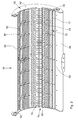
- the FIG. 2 shows a perspective view of the concave 34.
- This or a similar concave could also be used as a separating basket 36.
- the concave 34 includes side cheeks 62 which are oriented parallel to each other and spaced from each other. Between the cheeks 62 arc strips 64 are distributed, which are also oriented parallel to each other and to the cheeks 62 and spaced from each other. The flow direction of the crop is in the FIG. 2 directed from bottom left to top right.
- a concave inlet plate 66 is attached, followed by a flat plate 68.
- a first threshing section 70 which is constructed by bars 72 extending between the cheeks 72 and basket wires 74 guided by the bars.
- This first threshing section may be constructed of one or more removable inserts or inserts that may be interchangeable with other ports by other inserts.
- a second threshing section 76 Downstream of the second threshing section 70 is a second threshing section 76 fixedly connected to the cheeks 62, which is constructed by bars 78 extending between the cheeks 62 and basket wires 80 guided by the bars.
- the distances between the adjacent strips 78 and adjacent basket wires 80 in the second threshing section 76 are greater than the distances between the adjacent strips 72 and adjacent basket wires 74 in the first threshing section.
- the threshing basket 34 Downstream of the second threshing section 76, the threshing basket 34 is followed by a third threshing section 82, which is composed of three bars 84 of rectangular cross-section arranged immediately one behind the other and finger-like elements 86 attached thereto.
- the rods 84 extend between the cheeks 62 and are by a suitable adjusting drive (not shown, but it is based on the prior art after FR 637 181 A . US 2 457 259 A . US 4,875,891 A and FR 2 621 216 A1 referenced) rotatable synchronously about their longitudinal axes.
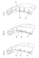
- the adjustment can be made on-site by an operator or by a power-operated actuator from the cab 60, in which case the operator can specify the position or it is controlled by a suitable control automatically on the basis of detected or input crop characteristics.
- the rods 84 with the elements 86 can between a radially innermost position, as shown in the FIG. 3 is shown and in the downstream of the gutflare ends of the elements 86 in the radial direction slightly beyond the gutflare following rod 84 and the cheeks 62 protrude, but not penetrate into the outer circle of the threshing drum 22, a tangential position, as shown in the FIG. 4 is shown and in which the elements 86 are each oriented towards the next bar in the direction of flow direction following rod 84, and an open position movable, as shown in the FIG. 5 is shown and in each of which a relation to the tangential position enlarged gap between the element 86 and the following in Guthneschetti rod 84 is formed.
- a tangential position as shown in the FIG. 4 is shown and in which the elements 86 are each oriented towards the next bar in the direction of flow direction following rod 84
- an open position movable as shown in the FIG. 5 is shown and in each of which a relation to the tang
Landscapes
- Life Sciences & Earth Sciences (AREA)
- Environmental Sciences (AREA)
- Threshing Machine Elements (AREA)
Applications Claiming Priority (1)
| Application Number | Priority Date | Filing Date | Title |
|---|---|---|---|
| DE102009047287.8A DE102009047287B4 (de) | 2009-11-30 | 2009-11-30 | Dreschkorb für ein Tangentialdreschwerk |
Publications (2)
| Publication Number | Publication Date |
|---|---|
| EP2327290A2 true EP2327290A2 (fr) | 2011-06-01 |
| EP2327290A3 EP2327290A3 (fr) | 2011-11-02 |
Family
ID=43640294
Family Applications (1)
| Application Number | Title | Priority Date | Filing Date |
|---|---|---|---|
| EP10190848A Withdrawn EP2327290A3 (fr) | 2009-11-30 | 2010-11-11 | Panier de battage pour une batteuse tangentielle |
Country Status (2)
| Country | Link |
|---|---|
| EP (1) | EP2327290A3 (fr) |
| DE (1) | DE102009047287B4 (fr) |
Cited By (10)
| Publication number | Priority date | Publication date | Assignee | Title |
|---|---|---|---|---|
| EP2594126A1 (fr) * | 2011-11-18 | 2013-05-22 | CLAAS Selbstfahrende Erntemaschinen GmbH | Panier de séparation |
| BE1021654B1 (de) * | 2011-12-14 | 2015-12-22 | Deere & Company | Dreschkorb für einen mähdrescher |
| US10342178B2 (en) | 2016-06-03 | 2019-07-09 | Claas Selbstfahrende Erntemaschinen Gmbh | Concave segment for harvest separation |
| WO2021222229A1 (fr) | 2020-04-28 | 2021-11-04 | Brian Robertson | Système de plaques de recouvrement concaves, dynamiques et automatisées, et procédés |
| US11317566B2 (en) | 2017-06-23 | 2022-05-03 | Thrashmaster Combines, LLC | Universal threshing concave for an agricultural combine |
| US11330764B2 (en) * | 2019-03-18 | 2022-05-17 | Jiangsu University | Threshing device with two-way pull wires and adjustable threshing clearance and combined harvester |
| US20240049645A1 (en) * | 2022-08-11 | 2024-02-15 | Deere & Company | Concave assembly with cover mechanism |
| CN117941543A (zh) * | 2024-03-26 | 2024-04-30 | 黑龙江八一农垦大学 | 一种双滚筒大豆种子脱粒机 |
| EP4378299A1 (fr) | 2022-11-11 | 2024-06-05 | AGCO International GmbH | Système de séparation de grains pour moissonneuse-batteuse |
| EP4393296A1 (fr) * | 2022-11-11 | 2024-07-03 | AGCO International GmbH | Système de séparation de grains pour moissonneuse-batteuse |
Families Citing this family (4)
| Publication number | Priority date | Publication date | Assignee | Title |
|---|---|---|---|---|
| DE102010061863A1 (de) | 2010-11-24 | 2012-05-24 | Deere & Company | Dreschkorb mit wenigstens einem demontierbaren Einsatz |
| DE102017119595A1 (de) * | 2017-08-25 | 2019-02-28 | Ab. Agri-Broker E.K. | Vorrichtung zum Herauslösen von Korn aus geernteten Ähren |
| RU198834U1 (ru) * | 2020-02-05 | 2020-07-29 | Общество с ограниченной ответственностью "Комбайновый завод "Ростсельмаш" | Подбарабанье молотильного устройства зерноуборочного комбайна |
| DE102021128494A1 (de) * | 2021-11-02 | 2023-05-04 | Deere & Company | Dreschkorb für einen Mähdrescher |
Citations (6)
| Publication number | Priority date | Publication date | Assignee | Title |
|---|---|---|---|---|
| FR637181A (fr) | 1927-07-07 | 1928-04-24 | Perfectionnements apportés dans les machines à battre | |
| US2457259A (en) | 1944-11-13 | 1948-12-28 | Fred M Moll | Disappearing tooth bars for concaves |
| FR2621216A1 (fr) | 1987-10-01 | 1989-04-07 | Moulet Andre | Contre-batteur perfectionne pour moissonneuse-batteuse |
| US4875891A (en) | 1987-03-02 | 1989-10-24 | Deere & Company | Separating grate for a grain harvester |
| EP1066746A1 (fr) * | 1999-07-07 | 2001-01-10 | Deere & Company | Contre-batteur |
| EP1197136A1 (fr) | 2000-09-15 | 2002-04-17 | Case Harvesting Systems GmbH | Contrebatteur pour moissonneuse-batteuse |
Family Cites Families (1)
| Publication number | Priority date | Publication date | Assignee | Title |
|---|---|---|---|---|
| US1269109A (en) | 1918-03-25 | 1918-06-11 | Peter A Noack | Threshing-machine. |
-
2009
- 2009-11-30 DE DE102009047287.8A patent/DE102009047287B4/de active Active
-
2010
- 2010-11-11 EP EP10190848A patent/EP2327290A3/fr not_active Withdrawn
Patent Citations (6)
| Publication number | Priority date | Publication date | Assignee | Title |
|---|---|---|---|---|
| FR637181A (fr) | 1927-07-07 | 1928-04-24 | Perfectionnements apportés dans les machines à battre | |
| US2457259A (en) | 1944-11-13 | 1948-12-28 | Fred M Moll | Disappearing tooth bars for concaves |
| US4875891A (en) | 1987-03-02 | 1989-10-24 | Deere & Company | Separating grate for a grain harvester |
| FR2621216A1 (fr) | 1987-10-01 | 1989-04-07 | Moulet Andre | Contre-batteur perfectionne pour moissonneuse-batteuse |
| EP1066746A1 (fr) * | 1999-07-07 | 2001-01-10 | Deere & Company | Contre-batteur |
| EP1197136A1 (fr) | 2000-09-15 | 2002-04-17 | Case Harvesting Systems GmbH | Contrebatteur pour moissonneuse-batteuse |
Cited By (15)
| Publication number | Priority date | Publication date | Assignee | Title |
|---|---|---|---|---|
| EP2594126A1 (fr) * | 2011-11-18 | 2013-05-22 | CLAAS Selbstfahrende Erntemaschinen GmbH | Panier de séparation |
| RU2604512C2 (ru) * | 2011-11-18 | 2016-12-10 | КЛААС Зельбстфаренде Эрнтемашинен ГмбХ | Решето сепаратора |
| BE1021654B1 (de) * | 2011-12-14 | 2015-12-22 | Deere & Company | Dreschkorb für einen mähdrescher |
| US10342178B2 (en) | 2016-06-03 | 2019-07-09 | Claas Selbstfahrende Erntemaschinen Gmbh | Concave segment for harvest separation |
| US12439856B2 (en) | 2017-06-23 | 2025-10-14 | Thrashmaster Concaves, LLC | Universal threshing concave for an agricultural combine |
| US11317566B2 (en) | 2017-06-23 | 2022-05-03 | Thrashmaster Combines, LLC | Universal threshing concave for an agricultural combine |
| US11330764B2 (en) * | 2019-03-18 | 2022-05-17 | Jiangsu University | Threshing device with two-way pull wires and adjustable threshing clearance and combined harvester |
| EP4125322A4 (fr) * | 2020-04-28 | 2023-09-13 | Brian Robertson | Système de plaques de recouvrement concaves, dynamiques et automatisées, et procédés |
| WO2021222229A1 (fr) | 2020-04-28 | 2021-11-04 | Brian Robertson | Système de plaques de recouvrement concaves, dynamiques et automatisées, et procédés |
| US20240049645A1 (en) * | 2022-08-11 | 2024-02-15 | Deere & Company | Concave assembly with cover mechanism |
| US12507632B2 (en) * | 2022-08-11 | 2025-12-30 | Deere & Company | Concave assembly with cover mechanism |
| EP4378299A1 (fr) | 2022-11-11 | 2024-06-05 | AGCO International GmbH | Système de séparation de grains pour moissonneuse-batteuse |
| EP4393296A1 (fr) * | 2022-11-11 | 2024-07-03 | AGCO International GmbH | Système de séparation de grains pour moissonneuse-batteuse |
| CN117941543A (zh) * | 2024-03-26 | 2024-04-30 | 黑龙江八一农垦大学 | 一种双滚筒大豆种子脱粒机 |
| CN117941543B (zh) * | 2024-03-26 | 2024-06-07 | 黑龙江八一农垦大学 | 一种双滚筒大豆种子脱粒机 |
Also Published As
| Publication number | Publication date |
|---|---|
| DE102009047287B4 (de) | 2024-07-04 |
| DE102009047287A1 (de) | 2011-06-01 |
| EP2327290A3 (fr) | 2011-11-02 |
Similar Documents
| Publication | Publication Date | Title |
|---|---|---|
| DE102009047287B4 (de) | Dreschkorb für ein Tangentialdreschwerk | |
| EP2591664B1 (fr) | Crible pour une installation de nettoyage d'une moissonneuse-batteuse | |
| DE60016718T2 (de) | Dresch- und trenneinheit für axialflussmähdrescher | |
| DE60222881T2 (de) | Schrägförder für landwirtschaftliche erntemaschine | |
| EP3420803B1 (fr) | Element de séparation ou de battage pour les récoltes céréalières | |
| DE102012210649B4 (de) | Tangentialdreschwerk mit einer Fördertrommel und einer Dresch- oder Abscheidetrommel | |
| EP2457434B1 (fr) | Panier de battage doté d'au moins un insert démontable | |
| DE2430718B2 (de) | Mähdrescher | |
| EP2014149B1 (fr) | Tambour rotatif de séparation pour une batteuse à plusieurs cylindres | |
| EP3075226B1 (fr) | Panier de battage ou de séparation dôté d'au moins un insert démontable | |
| EP2036425B2 (fr) | Agencement de panier de battage pour une moissonneuse-batteuse | |
| EP4209123B1 (fr) | Contre-batteur pour moissonneuse-batteuse | |
| BE1021663B1 (de) | Mehrtrommeldreschwerk | |
| EP3028560B1 (fr) | Système de contre-batteur de moissonneuse-batteuse | |
| EP2596696B1 (fr) | Moissonneuse-batteuse avec un dispositif de séparation et de battage conçu comme un agencement à plusieurs tambours | |
| BE1022970B1 (de) | Verstellanordnung zur Verstellung des Arbeitsspaltes eines Korbes einer Dresch- und/oder Trenneinrichtung | |
| BE1021334B1 (de) | Mähdrescher mit einer zwischen der drescheinrichtung und der reinigung angeordneten nachdrescheinrichtung | |
| DE102018118979B4 (de) | Konfiguration eines konkaven Dreschkorbelementes mit drei Abschnitten und Anpassungsmechanismus für eine landwirtschaftliche Erntekombine | |
| EP2764766A1 (fr) | Mécanisme de battage doté d'un tire-paille et d'un rouleau racleur | |
| DE102011088546B4 (de) | Mähdrescher | |
| DE1482255C (de) | Mähdrescher | |
| DE102005048052A1 (de) | Erntegutresteverteileinrichtung für einen Mähdrescher | |
| DE1482255B (de) | Mähdrescher |
Legal Events
| Date | Code | Title | Description |
|---|---|---|---|
| PUAI | Public reference made under article 153(3) epc to a published international application that has entered the european phase |
Free format text: ORIGINAL CODE: 0009012 |
|
| AK | Designated contracting states |
Kind code of ref document: A2 Designated state(s): AL AT BE BG CH CY CZ DE DK EE ES FI FR GB GR HR HU IE IS IT LI LT LU LV MC MK MT NL NO PL PT RO RS SE SI SK SM TR |
|
| AX | Request for extension of the european patent |
Extension state: BA ME |
|
| PUAL | Search report despatched |
Free format text: ORIGINAL CODE: 0009013 |
|
| AK | Designated contracting states |
Kind code of ref document: A3 Designated state(s): AL AT BE BG CH CY CZ DE DK EE ES FI FR GB GR HR HU IE IS IT LI LT LU LV MC MK MT NL NO PL PT RO RS SE SI SK SM TR |
|
| AX | Request for extension of the european patent |
Extension state: BA ME |
|
| RIC1 | Information provided on ipc code assigned before grant |
Ipc: A01F 12/24 20060101AFI20110928BHEP |
|
| 17P | Request for examination filed |
Effective date: 20120502 |
|
| 17Q | First examination report despatched |
Effective date: 20150227 |
|
| GRAP | Despatch of communication of intention to grant a patent |
Free format text: ORIGINAL CODE: EPIDOSNIGR1 |
|
| INTG | Intention to grant announced |
Effective date: 20160728 |
|
| RAP1 | Party data changed (applicant data changed or rights of an application transferred) |
Owner name: DEERE & COMPANY |
|
| STAA | Information on the status of an ep patent application or granted ep patent |
Free format text: STATUS: GRANT OF PATENT IS INTENDED |
|
| STAA | Information on the status of an ep patent application or granted ep patent |
Free format text: STATUS: THE APPLICATION IS DEEMED TO BE WITHDRAWN |
|
| 18D | Application deemed to be withdrawn |
Effective date: 20161208 |