EP2327334B1 - Dispositif de positionnement auxiliaire pour ensemble coulissant - Google Patents
Dispositif de positionnement auxiliaire pour ensemble coulissant Download PDFInfo
- Publication number
- EP2327334B1 EP2327334B1 EP09177467A EP09177467A EP2327334B1 EP 2327334 B1 EP2327334 B1 EP 2327334B1 EP 09177467 A EP09177467 A EP 09177467A EP 09177467 A EP09177467 A EP 09177467A EP 2327334 B1 EP2327334 B1 EP 2327334B1
- Authority
- EP
- European Patent Office
- Prior art keywords
- slide
- slide member
- wall
- slot
- engaging
- Prior art date
- Legal status (The legal status is an assumption and is not a legal conclusion. Google has not performed a legal analysis and makes no representation as to the accuracy of the status listed.)
- Active
Links
Images






Classifications
-
- A—HUMAN NECESSITIES
- A47—FURNITURE; DOMESTIC ARTICLES OR APPLIANCES; COFFEE MILLS; SPICE MILLS; SUCTION CLEANERS IN GENERAL
- A47B—TABLES; DESKS; OFFICE FURNITURE; CABINETS; DRAWERS; GENERAL DETAILS OF FURNITURE
- A47B88/00—Drawers for tables, cabinets or like furniture; Guides for drawers
- A47B88/40—Sliding drawers; Slides or guides therefor
- A47B88/453—Actuated drawers
- A47B88/46—Actuated drawers operated by mechanically-stored energy, e.g. by springs
- A47B88/47—Actuated drawers operated by mechanically-stored energy, e.g. by springs having both self-opening and self-closing mechanisms which interact with each other
Definitions
- the present invention relates to an auxiliary positioning device, and more particularly, to an auxiliary positioning device for a slide assembly to control the slide assembly to be positioned by operation of the auxiliary positioning device when the slide assembly is to be closed.
- U.S. Patent No. 5,040,833 to Brunnert discloses a "Closing Device For Drawers", which includes a drawer installed to a furniture body. The drawer is movable between a closed position and an open position, as shown in Figs. 2-6 , 18a and 18b of U.S. Patent No. 5,040,833 .
- a spring is located between the drawer and the furniture body.
- a holding member is fixed to the furniture body and has a front end.
- a latch member is fixed to the drawer and includes a first raised area and a second raised area, wherein the second raised area includes a notch which is located corresponding to the first raised area.
- the second raised area further includes an inclined guide track.
- the front end of the holding member When the drawer is located at the closed position relative to the furniture body, the front end of the holding member is guided by the inclined guide track of the second raised area to be engaged with the notch of the second raised area.
- the front end of the holding member When the drawer applies a force relative to the furniture body, the front end of the holding member is guided by the guide track of the first raised area to be engaged with another guide track and is disengaged from the notch.
- the drawer is pushed by the force of the spring and moved to a self-opening position relative to the furniture body.
- the front end of the holding member is in a free status when the drawer is opened relative to the furniture body and the holding member is disengaged from the latch member. In this status, when the drawer is pushed to its closed position, the drawer can only travel through the same processes to let the front end of the holding member engage with the notch of the latch member.
- the present invention provides an improved structure to include the functions which the conventional closing device does not have.
- the present invention relates to a slide assembly with an auxiliary positioning device and comprises a first slide member and a second slide member which is longitudinally and slidably movable relative to the first slide member.
- the second slide member has a stored opening force relative to the first slide member when in a closed position.
- the auxiliary positioning device comprises a positioning member, a guiding base and a link member.
- the positioning member is pivotally connected to the first slide member and includes a pin member.
- the guiding base is attached to the second slide member and comprises a first passage, a first slot and a first wall, wherein the first wall has a first guide surface facing the first passage.
- the guiding base further comprises a second passage, a second slot and a second wall, wherein the second wall has a second guide surface facing the second passage.
- the guiding base further comprises a separation body having a guiding end which faces the first slot.
- the guiding base further comprises an engaging body having an engaging surface which has a portion facing the second slot.
- the guiding base further comprises a third passage, a third slot and a third wall, wherein the third wall has a third guide surface facing the rest portion of the engaging surface.
- the guiding base further comprises a fourth wall having a fourth guide surface.
- the link member is located corresponding to the positioning member.
- the pin member When the second slide member is in a closed position relative to the first slide member, the pin member is located in a first path in the first passage of the guiding base.
- the pin member When the second slide member applies a force relative to the first slide member, the pin member is guided by the first guide surface of the first wall and moves from the first path to the first slot. The pin member is located at a first position.
- the pin member When the force is released, the pin member is guided by the guiding end of the separation body and moves from the first position to a second path in the second passage.
- the pin member When the second slide member is retracted relative to the first slide member, the pin member is guided by the second guide surface of the second wall and moves from the second path to the second slot via the second passage. The pin member is located in a second position. When the second slide member is released, the pin member moves away from the second position and is engaged with the engaging surface of the engaging body and located in a third position.
- the pin member When the second slide member further applies a force relative to the first slide member again, the pin member is guided by the third guide surface of the third wall and moves from the third position into the third slot. The pin member is located in a fourth position. When the second slide member is released, the pin member is guided by the fourth guide surface of the fourth wall.
- the link member pivots the positioning member by the movement of the second slide member.
- the primary object of the present invention is to provide an auxiliary positioning device for a slide assembly to control the slide assembly to be positioned by operation of the auxiliary positioning device when the slide assembly is to be closed, such that the slide assembly is easily operated whenever it is closed or opened.
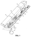
- the slide assembly of the present invention comprises a first slide member 10, a second slide member 12 longitudinally and slidably movable relative to the first slide member 10, a movable member 14 connected to the first slide member 10 and an auxiliary positioning device 16.
- the first slide member 10 includes a bottom board 18.
- the second slide member 12 includes a first connector 20 and a second connector 22.
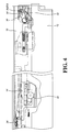
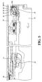
- the movable member 14 is linked to move by the first connector 20 of the second slide member 12. For example, when the second slide member 12 is retracted relative to the first slide member 10 as shown in Fig. 4 , the movable member 14 is connected to a first elastic member 24 and includes a first force F1 in a first direction and the first force F1 applies to the second slide member 12. The movable member 14 is engaged with the first connector 20, such that the second slide member 12 has a self-closing function relative to the first slide member 10 by the force of the first elastic member 24. When the second slide member 12 applies a force to the first slide member 10, as shown in Fig.
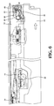
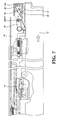
- the second slide member 12 is pushed to a distance, the first connector 20 is disengaged from the movable member 14 as shown in Figs. 6 and 7 , and the force of the first elastic member 24 does not apply to the second slide member 12.
- the first force F1 that the movable member 14 applies to the second slide member 12 is released.
- the second slide member 12 has a self-opening function relative to the first slide member 10.
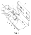
- the auxiliary positioning device 16 comprises a positioning member 30 which is pivotably connected to the first slide member 10, a guiding base 32 attached to the second slide member 12, and a link member 34 movably connected to the first slide member 10.
- the positioning member 30 includes a pin member 36 and a contact end 38 which is located at a different position from that of the pin member 36.
- the positioning member 30 is linked to move by the link member 34 to keep the pin member 36 at a specific position.
- the guiding base 32 comprises a first wall 40, a second wall 42, a third wall 44, a fourth wall 46, a connection wall 48, a separation body 50 and an engaging body 52.
- the connection wall 48 is connected to the first, second, third and fourth walls 40, 42, 44, 46.
- the first wall 40 and the separation body 50 define a first passage 54.
- the separation body 50 and the engaging body 52 define a second passage 56.
- the engaging body 52 and the fourth wall 46 define a third passage 58.
- the separation body 50 has a guiding end 60.
- the engaging body 52 includes an engaging surface 62 which is a recessed area.
- the first, second and connection walls 40, 42, 48 define a first slot 64a.
- the second, third and connection walls 42, 44, 48 define a second slot 64b.
- the third, fourth and the connection walls 44, 46, 48 define a third slot 64c.
- the third slot 64c faces the third passage 58.
- the first wall 40 has a first guide surface 66 in the longitudinal direction facing a portion of the first passage 54 so as to guide the first passage 54 to face the first slot 64a.
- the second wall 42 has a second guide surface 68 in the longitudinal direction facing a portion of the second passage 56 so as to guide the second passage 56 to face the second slot 64b.
- the third wall 44 has a third guide surface 70 in the longitudinal direction facing a portion of the engaging surface 62 of the engaging body 52.
- the fourth wall 46 includes a fourth guide surface 72 so as to guide the pin member 36 of the positioning member 30 to face the second passage 56.
- a portion of the guiding end 60 of the separation body 50 faces a portion of the first slot 64a in the longitudinal direction so as to guide the first slot 64a to face the second passage 56.
- the rest portion of the engaging surface 62 of the engaging body 52 faces the second slot 64b in the longitudinal direction.
- the engaging body 52 further includes a fifth guide surface 74 which faces the second passage 56.
- the link member 34 is moved by the movable member 14.
- the link member 34 has an operation end 76 to lean against the contact end 38 of the positioning member 30.
- the positioning member 30 is pivoted by the link member 34 and rotated an angle relative to the first slide member 10.
- the second slide member 12 is in a retracted position relative to the first slide member 10.
- the pin member 36 of the positioning member 30 is located in a first path R1 relative to the first passage 54 of the guiding base 32 and the first force F1 of the movable member 14 applies to the second slide member 12 so that the second slide member 12 is maintained in the retracted position relative to the first slide member 10.
- the second slide member 12 applies a force to the first slide member 10, the guiding base 32 moves relative to the positioning member 30 and the pin member 36 of the positioning member 30 is guided by the first guide surface 66 of the first wall 40 of the guiding base 32 from the first path R1 in the first passage 54 to the first slot 64a of the guiding base 32, and the pin member 36 is located at a first position P1.
- the first connector 20 of the second slide member 12 is disengaged from the movable member 14 so that the first force F1 from the first elastic member 24 no longer applies to the second slide member 12.
- the pushing member 26 and the second elastic member 28 apply the second force F2 to the second connector 22 of the second slide member 12 (referring to Fig. 1 and the disclosure in European Patent Application 09165988.8 ).
- the second slide member 12 is automatically opened relative to the first slide member 10. As shown in Figs.
- the guiding base 32 is moved together with the second slide member 12 relative to the positioning member 30, the pin member 36 of the positioning member 30 is guided by the guiding end 60 of the separation body 50 and moves from the first position P1 in the first slot 64a to a second path R2 via the second passage 56 of the guiding base 32.
- the second slide member 12 freely pops out and can be pulled out relative to the first slide member 10.
- the second slide member 12 When the force applied to the first slide member 10 by the second slide member 12 is released, the second slide member 12 only pops out a small distance relative to the first slide member 10. If the second slide member 12 is not pulled out and moves the movable member 14, the second slide member 12 is pushed inward relative to the first slide member 10, as shown in Fig. 8 , the guiding base 32 is moved relative to the positioning member 30, and the pin member 36 of the positioning member 30 is moved from the second path R2 to the second slot 64b and located at a second position P2 by the guidance of the second guide surface 68 of the second wall 42 and via the second passage 56.
- Fig. 9 shows the action following the status in Fig. 8 .
- the second slide member 12 will drive the guiding base 32 relative to the first slide member 10 to move from the positioning member 30 by the second force F2.
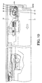
- the pin member 36 of the positioning member 30 moves away from the second position P2 and is engaged with the engaging surface 62 of the engaging body 52 so as to be positioned at a third positioning P3.
- the second slide member 12 When the second slide member 12 is popped out relative to the first slide member 10 and the second slide member 12 is not pulled relative to the first slide member 10 to a distance for moving the movable member 14 to a position that stores a force to return the second slide member 12 automatically, by changing the path between the pin member 36 in the first passage 54 and the second passage 56 as well as the pin member 36 to engage with the engaging surface 62 of the engaging body 52, the second slide member 12 can be pushed inward relative to the first slide member 10 and maintained at the retracted position. Accordingly, the second slide member 12 has no need to be pulled out for a longer distance relative to the first slide member 10.
- the guiding base 32 moves relative to the positioning member 30 and the pin member 36 is guided by the third guide surface 70 of the third wall 44 from the engaging surface 62 of the engaging body 52 to the third slot 64c of the guiding base 32.
- the pin member 36 is then located at a fourth position P4.
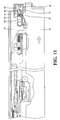
- the second slide member 12 when the second slide member 12 is released again, the second slide member 12 freely pops out or is pulled out to a further distance relative to the first slide member 10, as shown in Fig. 11 .
- the pin member 36 moves along the fourth guide surface 72 of the fourth wall 46 of the guiding base 32.
- the pin member 36 is guided by the fifth guide surface 74 of the engaging body 52 and enters the second passage 56.
- Fig. 12 shows that when the second slide member 12 is pulled out relative to the first slide member 10 and the movable member 14 is moved to a position that stores sufficient return force to bring the second slide member 12, the link member 34 is moved by the movement of the movable member 14.
- the operation end 76 of the link member 34 leans against the contact end 38 of the positioning member 30 to pivot the positioning member 30 to move the pin member 36 back to the first passage 54, which corresponds to the first path R1. Accordingly, when the second slide member 12 is retracted relative to the first slide member 10, the second slide member 12 is back to the status as shown in Fig. 4 .
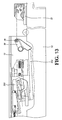
- Fig. 13 shows a second embodiment of the present invention, wherein the movable member 200 includes a link member 202 which extends to the positioning member 30.
- the positioning member 30 is pivoted by the link member 202 and the pin member 36 of the positioning member 30 is located in the first path R1.
- Fig. 14 shows a third embodiment of the present invention, wherein a link member 300 is fixed to the second slide member 12 and located corresponding to the positioning member 30.
- the positioning member 30 is pivoted by the link member 300 and the pin member 36 of the positioning member 30 is located in the first path R1.
- Fig. 15 shows a fourth embodiment of the present invention, which includes a guiding base 400 and a connection board 402.
- the guiding base 400 includes a pair of engaging portions 404 and an engaging hole 406.
- the connection board 402 includes a pair of engaging slots 408 and an engaging member 410 corresponding to the engaging hole 406 so as to position the guiding base 400, as shown in Fig. 16 .
- the connection board 402 is connected to the second slide member 12 such that the guiding base 400 is connected to the second slide member 12.
- Figs. 17 and 18 show a fifth embodiment of the present invention, which includes a guiding base 500, a connection board 502, an adjusting member 504 and a pivot member 506.
- the guiding base 500 includes a protrusion 508, a connection member 510, a longitudinal groove 512, and a recess 514.
- the connection board 502 includes a first longitudinal slot 516, a second longitudinal slot 518, a fixing hole 520 and a protruding portion 522.
- the protrusion 508 extends beyond the first longitudinal slot 516.
- the connection member 510 is inserted in the second longitudinal slot 518.
- the protruding portion 522 is engaged with a portion of the recess 514 so that the guiding base 500 is movably connected to the connection board 502 and moves longitudinally.
- the adjusting member 504 includes an aperture 524 and a spiral recess 526.
- the pivot member 506 extends through the aperture 524 of the adjusting member 504 and is connected with the fixing hole 520 of the connection board 502, such that the adjusting member 504 is rotatable relative to the connection board 502.
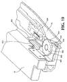
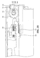
- Figs. 19 and 20 show the assembled configuration of the fifth embodiment.
- a portion of the second slide member 12 is connected with the longitudinal groove 512 of the guiding base 500.
- the connection board 502 is fixed to the second slide member 12.
- the protrusion 508 of the guiding base 500 is movable in the spiral recess 526.
- the protrusion 508 of the guiding base 500 will be moved in the spiral recess 526 and the guiding base 500 will be moved longitudinally relative to the connection board 502. Therefore, when the guiding base 500 is adjusted to move longitudinally relative to the second slide member 12 by operation of the adjusting member 504, a relative position between the guiding base 500 and the positioning member 30 is adjusted.
- this embodiment further includes a third elastic member 528 and a stop 530 which is urged by the third elastic member 528 to be contact with an end outside of the longitudinal groove 512 of the guiding base 500, such that the depth in the longitudinal direction of the second slide member 12 relative to the first slide member 10 can also be adjusted. This allows the assemblers to micro-adjust the depth of the drawer in the furniture.
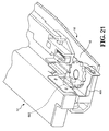
- Fig. 21 shows a sixth embodiment of the present invention, wherein a roller 602 is connected to a guiding base 600 and the roller 620 has a rolling surface facing the bottom board 18 of the first slide member 10.
- the second slide member 12 slightly moves downward relative to the first slide member 10, the rolling surface of the roller 602 is supported between the guiding base 600 and the bottom board 18 of the first slide member 10 so as to ensure that the guiding base 600 is maintained at a position relative to the positioning member 30.
Landscapes
- Engineering & Computer Science (AREA)
- Mechanical Engineering (AREA)
- Drawers Of Furniture (AREA)
Claims (14)
- Un ensemble coulissant avec un dispositif auxiliaire de positionnement (16), comprenant :un premier élément coulissant (10) ;un second élément coulissant (12) déplaçable longitudinalement et de façon coulissante par rapport au premier élément coulissant (10), le second élément coulissant (12) ayant une force d'ouverture réservée par rapport au premier élément coulissant (10) lorsqu'en position fermée ;le dispositif auxiliaire de positionnement (16) comprenant :un élément de positionnement (30) relié de façon pivotante au premier élément coulissant (10), l'élément de positionnement (30) comprenant un élément mâle (36) ;une base de guidage (32) attachée au second élément coulissant (12), la base de guidage (32) comprenant un premier passage (54), une première entaille (64a) et une première paroi (40), la première paroi (40) ayant une première surface de guidage (66) en face du premier passage (54) ; un deuxième passage (56), une deuxième entaille (64b) et une deuxième paroi (42), la deuxième paroi (42) ayant une deuxième surface de guidage (68) en face du deuxième passage (56) ; un corps de séparation (50) ayant une extrémité de guidage (60) faisant face à la première entaille (64a) ; un corps d'engagement (52) ayant une surface d'engagement (62) qui a une partie en face de la deuxième entaille (64b) ; un troisième passage (58), une troisième entaille (64c) et une troisième paroi (44), la troisième paroi (44) ayant une troisième surface de guidage (70) en face de la partie de repos de la surface d'engagement (62) ; une quatrième paroi (46) ayant une quatrième surface de guidage (72) ; etun élément de liaison (34) situé de manière correspondante à l'élément de positionnement (30) ;où le dispositif auxiliaire de positionnement (16) et formé et arrangé de sorte que- l'élément mâle (36) est situé dans une première trajectoire (R1) dans le premier passage (54) de la base de guidage (32) quand le second élément coulissant (12) est en position fermée par rapport au premier élément coulissant (10) ;- l'élément mâle (36) est guidé par la première surface de guidage (66) de la première paroi (40) et se déplace de la première trajectoire (R1) à la première entaille (64a) et l'élément mâle (36) est situé à une première position (P1) quand le second élément coulissant (12) applique une force par rapport au premier élément coulissant (10) ;- l'élément mâle (36) est guidé par l'extrémité de guidage (60) du corps de séparation (50) et se déplace de la première position (P1) à une deuxième trajectoire (R2) dans le second passage (56) quand la force est libérée ;- l'élément mâle (36) est guidé par la seconde surface de guidage (68) de la seconde paroi (42) et se déplace de la deuxième trajectoire (R2) à la seconde entaille (64b) via le second passage (56) et l'élément mâle (36) est situé dans une deuxième position (P2) quand le second élément coulissant (12) est rétracté par rapport au premier élément coulissant (10) ; l'élément mâle (36) s'éloigne de la deuxième position (P2) pour s'engager avec la surface d'engagement (62) du corps d'engagement (52) et situé dans une troisième position (P3) quand le second élément coulissant (12) est libéré ;- l'élément mâle (36) est guidé par la troisième surface de guidage (70) de la troisième paroi (44) et s'éloigne de la troisième position (P3) dans la troisième entaille (64c) et l'élément mâle (36) est situé dans une quatrième position (P4) quand le second élément coulissant (12) applique à nouveau une force par rapport au premier élément coulissant (10) ;- l'élément mâle (36) est guidé par la quatrième surface de guidage (72) de la quatrième paroi (46) quand le second élément coulissant (12) est libéré ;- l'élément de liaison (34) fait pivoter l'élément de positionnement (30) par le mouvement du second élément coulissant (12) quand le second élément coulissant (12) se déplace par rapport au premier élément coulissant (10).
- L'ensemble coulissant tel que revendiqué dans la revendication 1, où le premier passage (54) est défini par la première paroi (40) et le corps de séparation (50) ; le second passage (56) est défini par le corps de séparation (50) et le corps d'engagement (52) ; le troisième passage (58) est défini par le corps d'engagement (52) et la quatrième paroi (46) ; la première entaille (64a) est définie par la première et la deuxième paroi (40,42), la seconde entaille (64b) est définie par la deuxième et la troisième paroi (42,44) ; la troisième entaille (64c) est définie par la troisième et la quatrième paroi (44,46).
- L'ensemble coulissant tel que revendiqué dans la revendication 1, où la base de guidage (32) comprend une paroi de connexion (48) qui est reliée à la première, deuxième et troisième paroi (40, 42, 44), et la paroi de connexion (48) est située de manière correspondante à la première et deuxième entailles (64a, 64b).
- L'ensemble coulissant tel que revendiqué dans la revendication 1, où la surface d'engagement (62) du corps d'engagement (52) est un emplacement évidé.
- L'ensemble coulissant tel que revendiqué dans la revendication 1, comprenant en outre une plaque de connexion (402) qui comprend une paire d'entailles d'engagement (408) et un élément d'engagement (410), la base de guidage (400) comprenant une paire de parties d'engagement (404) de manière correspondante aux entailles d'engagement (408) et un trou d'engagement (406) de manière correspondante à l'élément d'engagement (410) pour s'engager mutuellement.
- L'ensemble coulissant tel que revendiqué dans la revendication 1, comprenant en outre une plaque de connexion (502), un élément de réglage (504) et un élément de pivot (506), la plaque de connexion (502) étant fixée au second élément coulissant (12) et reliée à la base de guidage (500), la plaque de connexion (502) comprenant une première entaille longitudinale (516), une seconde entaille longitudinale (518), un trou de fixation (520) et une partie saillante (522), la base de guidage (500) comprenant a protrusion (508), un élément de connexion (510), une rainure longitudinale (512) et un évidement (514), la protrusion (508) s'étendant au-delà de la première entaille longitudinale (516) et l'élément de connexion (510) engagé avec la seconde entaille longitudinale (518), la partie saillante (522) engagée avec une partie de l'évidement (514) de sorte que la base de guidage (500) est reliée à la plaque de connexion (502) et se déplace longitudinalement, l'élément de réglage (504) comprenant une ouverture (524) et une empreinte spirale (526), l'élément de pivot (506) au travers de l'ouverture (524) de l'élément de réglage (504) et relié avec le trou de fixation (520) de la plaque de connexion (502), une partie du second élément coulissant (12) reliée avec la rainure longitudinale (512) de la base de guidage (500), la protrusion (508) de la base de guidage (500) engagée avec l'empreinte spirale (526).
- L'ensemble coulissant tel que revendiqué dans la revendication 1, où le premier élément coulissant (10) a un élément déplaçable (14) qui lui est relié et le second élément coulissant (12) a un premier connecteur (20), l'élément déplaçable (14) étant relié pour se déplacer grâce au premier connecteur (20) du second élément coulissant (12), l'élément de liaison (34) étant actionné par l'élément déplaçable (14) pour pousser et tourner l'élément de positionnement (30).
- L'ensemble coulissant tel que revendiqué dans la revendication 7, où l'élément de liaison (34) est relié de façon amovible au premier élément coulissant (10).
- L'ensemble coulissant tel que revendiqué dans la revendication 7, où l'élément de liaison (34) est relié à l'élément déplaçable (14).
- L'ensemble coulissant tel que revendiqué dans la revendication 1, où l'élément de liaison (34) est relié au second élément coulissant (12).
- L'ensemble coulissant tel que revendiqué dans la revendication 7, où l'élément déplaçable (14) est relié avec un premier élément élastique (24) qui applique une première force dans une première direction au second élément coulissant (12) pour que le second élément coulissant (12) se ferme automatiquement par rapport au premier élément coulissant (10) quand le second élément coulissant (12) est rétracté par rapport au premier élément coulissant (10).
- L'ensemble coulissant tel que revendiqué dans la revendication 1, où la force d'ouverture réservée est définie par un deuxième élément élastique (28) et un élément poussoir (26) qui est relié avec le deuxième élément élastique (28), le second élément coulissant (12) comprenant un second connecteur (22), l'élément poussoir (26) s'engageant avec le second connecteur (22) par une force du deuxième élément élastique (28) pour que le second élément coulissant (12) ait la force d'ouverture réservée quand le second élément coulissant (12) est rétracté par rapport au premier élément coulissant (10).
- L'ensemble coulissant tel que revendiqué dans la revendication 1, comprenant en outre un troisième élément élastique (528) et un arrêt (530) qui est forcé par le troisième élément élastique (528) pour venir contre une extrémité à l'extérieur d'une rainure longitudinale (512) de la base de guidage (500).
- L'ensemble coulissant tel que revendiqué dans la revendication 1, comprenant en outre un rouleau (602) relié à la base de guidage (600), le rouleau (602) ayant une surface de roulage en face d'une plaque inférieure (18) du premier élément coulissant (10).
Priority Applications (3)
| Application Number | Priority Date | Filing Date | Title |
|---|---|---|---|
| EP09177467A EP2327334B1 (fr) | 2009-11-30 | 2009-11-30 | Dispositif de positionnement auxiliaire pour ensemble coulissant |
| ES09177467T ES2384020T3 (es) | 2009-11-30 | 2009-11-30 | Dispositivo de posicionamiento complementario para ensamblaje de corredera |
| DK09177467.9T DK2327334T3 (da) | 2009-11-30 | 2009-11-30 | Hjælpepositioneringsindretning til et glideaggregat |
Applications Claiming Priority (1)
| Application Number | Priority Date | Filing Date | Title |
|---|---|---|---|
| EP09177467A EP2327334B1 (fr) | 2009-11-30 | 2009-11-30 | Dispositif de positionnement auxiliaire pour ensemble coulissant |
Publications (2)
| Publication Number | Publication Date |
|---|---|
| EP2327334A1 EP2327334A1 (fr) | 2011-06-01 |
| EP2327334B1 true EP2327334B1 (fr) | 2012-05-16 |
Family
ID=42084589
Family Applications (1)
| Application Number | Title | Priority Date | Filing Date |
|---|---|---|---|
| EP09177467A Active EP2327334B1 (fr) | 2009-11-30 | 2009-11-30 | Dispositif de positionnement auxiliaire pour ensemble coulissant |
Country Status (3)
| Country | Link |
|---|---|
| EP (1) | EP2327334B1 (fr) |
| DK (1) | DK2327334T3 (fr) |
| ES (1) | ES2384020T3 (fr) |
Families Citing this family (1)
| Publication number | Priority date | Publication date | Assignee | Title |
|---|---|---|---|---|
| AT18075U1 (de) * | 2022-10-14 | 2023-12-15 | Blum Gmbh Julius | Antriebsvorrichtung für einen Möbelbeschlag oder einen Baubeschlag |
Family Cites Families (5)
| Publication number | Priority date | Publication date | Assignee | Title |
|---|---|---|---|---|
| AT395095B (de) | 1989-05-10 | 1992-09-10 | Blum Gmbh Julius | Schliessvorrichtung fuer schubladen |
| US6247733B1 (en) * | 1999-08-24 | 2001-06-19 | Southco, Inc. | Push-push latch with clicker |
| JP4462768B2 (ja) * | 2001-01-19 | 2010-05-12 | 株式会社ニフコ | 安全機能付ロック装置及び乗物用収納装置 |
| US7347515B1 (en) * | 2005-07-01 | 2008-03-25 | Gslide Corporation | Sliding rail assembly auto opening mechanism for drawer |
| US7374261B1 (en) * | 2006-12-08 | 2008-05-20 | Dynaslide Corporation | Push-open type slide structure |
-
2009
- 2009-11-30 ES ES09177467T patent/ES2384020T3/es active Active
- 2009-11-30 EP EP09177467A patent/EP2327334B1/fr active Active
- 2009-11-30 DK DK09177467.9T patent/DK2327334T3/da active
Also Published As
| Publication number | Publication date |
|---|---|
| EP2327334A1 (fr) | 2011-06-01 |
| DK2327334T3 (da) | 2012-07-23 |
| ES2384020T3 (es) | 2012-06-28 |
Similar Documents
| Publication | Publication Date | Title |
|---|---|---|
| US8100487B2 (en) | Auxiliary positioning device for slide assembly | |
| CA2699212C (fr) | Positionneur auxiliaire pour ensemble coulissant | |
| US7914093B2 (en) | Automatic position restoring slide rail device | |
| US8079653B2 (en) | Sliding track assembly | |
| US7708357B2 (en) | Automatic locking apparatus used in guide rail for drawer | |
| US8496306B2 (en) | Opening mechanism of slide assembly | |
| US6997529B1 (en) | Synchronizing device for a tri-sector slide | |
| EP3387950B1 (fr) | Ensemble de rails de glissement | |
| US20070046158A1 (en) | Closing device for drawers | |
| CN101330849A (zh) | 具有撞锁装置的抽屉滑道 | |
| US20140079347A1 (en) | Slide-track buffering device with a smoothly sliding carriage | |
| KR20060134042A (ko) | 완충장치 | |
| TW201715998A (zh) | 驅動機構 | |
| US11280126B2 (en) | Door closer arrangement | |
| US8186780B2 (en) | Adjustment device for slide assembly | |
| EP2532272B1 (fr) | Mécanisme d'ouverture d'un ensemble coulissant | |
| EP2327334B1 (fr) | Dispositif de positionnement auxiliaire pour ensemble coulissant | |
| US8857868B2 (en) | Engaging mechanism of closing device | |
| EP2371241B1 (fr) | Ensemble de rails de tiroir avec dispositif d'ouverture | |
| JP2006102294A (ja) | 飛び出し・引き込み装置 | |
| JP3159129U (ja) | スライドレール構成に用いる補助位置決め装置 | |
| CA2699211C (fr) | Dispositif de reglage pour ensemble coulissant | |
| CN102068129B (zh) | 用于滑轨总成的辅助定位装置 | |
| JP2010101075A (ja) | 戸当り | |
| CN116829799A (zh) | 用于柜中的抽屉的锁定装置、包括该装置的柜和抽屉轨道 |
Legal Events
| Date | Code | Title | Description |
|---|---|---|---|
| PUAI | Public reference made under article 153(3) epc to a published international application that has entered the european phase |
Free format text: ORIGINAL CODE: 0009012 |
|
| AK | Designated contracting states |
Kind code of ref document: A1 Designated state(s): AT BE BG CH CY CZ DE DK EE ES FI FR GB GR HR HU IE IS IT LI LT LU LV MC MK MT NL NO PL PT RO SE SI SK SM TR |
|
| 17P | Request for examination filed |
Effective date: 20110816 |
|
| RIC1 | Information provided on ipc code assigned before grant |
Ipc: A47B 88/04 20060101AFI20111103BHEP |
|
| GRAP | Despatch of communication of intention to grant a patent |
Free format text: ORIGINAL CODE: EPIDOSNIGR1 |
|
| GRAS | Grant fee paid |
Free format text: ORIGINAL CODE: EPIDOSNIGR3 |
|
| GRAA | (expected) grant |
Free format text: ORIGINAL CODE: 0009210 |
|
| AK | Designated contracting states |
Kind code of ref document: B1 Designated state(s): AT BE BG CH CY CZ DE DK EE ES FI FR GB GR HR HU IE IS IT LI LT LU LV MC MK MT NL NO PL PT RO SE SI SK SM TR |
|
| REG | Reference to a national code |
Ref country code: GB Ref legal event code: FG4D |
|
| REG | Reference to a national code |
Ref country code: CH Ref legal event code: EP |
|
| REG | Reference to a national code |
Ref country code: AT Ref legal event code: REF Ref document number: 557615 Country of ref document: AT Kind code of ref document: T Effective date: 20120615 |
|
| REG | Reference to a national code |
Ref country code: IE Ref legal event code: FG4D |
|
| REG | Reference to a national code |
Ref country code: ES Ref legal event code: FG2A Ref document number: 2384020 Country of ref document: ES Kind code of ref document: T3 Effective date: 20120628 |
|
| REG | Reference to a national code |
Ref country code: DE Ref legal event code: R096 Ref document number: 602009006995 Country of ref document: DE Effective date: 20120719 |
|
| REG | Reference to a national code |
Ref country code: DK Ref legal event code: T3 |
|
| REG | Reference to a national code |
Ref country code: NL Ref legal event code: VDEP Effective date: 20120516 |
|
| REG | Reference to a national code |
Ref country code: LT Ref legal event code: MG4D Effective date: 20120516 |
|
| PG25 | Lapsed in a contracting state [announced via postgrant information from national office to epo] |
Ref country code: FI Free format text: LAPSE BECAUSE OF FAILURE TO SUBMIT A TRANSLATION OF THE DESCRIPTION OR TO PAY THE FEE WITHIN THE PRESCRIBED TIME-LIMIT Effective date: 20120516 Ref country code: LT Free format text: LAPSE BECAUSE OF FAILURE TO SUBMIT A TRANSLATION OF THE DESCRIPTION OR TO PAY THE FEE WITHIN THE PRESCRIBED TIME-LIMIT Effective date: 20120516 Ref country code: IS Free format text: LAPSE BECAUSE OF FAILURE TO SUBMIT A TRANSLATION OF THE DESCRIPTION OR TO PAY THE FEE WITHIN THE PRESCRIBED TIME-LIMIT Effective date: 20120916 Ref country code: SE Free format text: LAPSE BECAUSE OF FAILURE TO SUBMIT A TRANSLATION OF THE DESCRIPTION OR TO PAY THE FEE WITHIN THE PRESCRIBED TIME-LIMIT Effective date: 20120516 Ref country code: PL Free format text: LAPSE BECAUSE OF FAILURE TO SUBMIT A TRANSLATION OF THE DESCRIPTION OR TO PAY THE FEE WITHIN THE PRESCRIBED TIME-LIMIT Effective date: 20120516 Ref country code: CY Free format text: LAPSE BECAUSE OF FAILURE TO SUBMIT A TRANSLATION OF THE DESCRIPTION OR TO PAY THE FEE WITHIN THE PRESCRIBED TIME-LIMIT Effective date: 20120516 Ref country code: NO Free format text: LAPSE BECAUSE OF FAILURE TO SUBMIT A TRANSLATION OF THE DESCRIPTION OR TO PAY THE FEE WITHIN THE PRESCRIBED TIME-LIMIT Effective date: 20120816 |
|
| PG25 | Lapsed in a contracting state [announced via postgrant information from national office to epo] |
Ref country code: SI Free format text: LAPSE BECAUSE OF FAILURE TO SUBMIT A TRANSLATION OF THE DESCRIPTION OR TO PAY THE FEE WITHIN THE PRESCRIBED TIME-LIMIT Effective date: 20120516 Ref country code: LV Free format text: LAPSE BECAUSE OF FAILURE TO SUBMIT A TRANSLATION OF THE DESCRIPTION OR TO PAY THE FEE WITHIN THE PRESCRIBED TIME-LIMIT Effective date: 20120516 Ref country code: PT Free format text: LAPSE BECAUSE OF FAILURE TO SUBMIT A TRANSLATION OF THE DESCRIPTION OR TO PAY THE FEE WITHIN THE PRESCRIBED TIME-LIMIT Effective date: 20120917 Ref country code: HR Free format text: LAPSE BECAUSE OF FAILURE TO SUBMIT A TRANSLATION OF THE DESCRIPTION OR TO PAY THE FEE WITHIN THE PRESCRIBED TIME-LIMIT Effective date: 20120516 |
|
| PG25 | Lapsed in a contracting state [announced via postgrant information from national office to epo] |
Ref country code: BE Free format text: LAPSE BECAUSE OF FAILURE TO SUBMIT A TRANSLATION OF THE DESCRIPTION OR TO PAY THE FEE WITHIN THE PRESCRIBED TIME-LIMIT Effective date: 20120516 |
|
| PG25 | Lapsed in a contracting state [announced via postgrant information from national office to epo] |
Ref country code: RO Free format text: LAPSE BECAUSE OF FAILURE TO SUBMIT A TRANSLATION OF THE DESCRIPTION OR TO PAY THE FEE WITHIN THE PRESCRIBED TIME-LIMIT Effective date: 20120516 Ref country code: CZ Free format text: LAPSE BECAUSE OF FAILURE TO SUBMIT A TRANSLATION OF THE DESCRIPTION OR TO PAY THE FEE WITHIN THE PRESCRIBED TIME-LIMIT Effective date: 20120516 Ref country code: NL Free format text: LAPSE BECAUSE OF FAILURE TO SUBMIT A TRANSLATION OF THE DESCRIPTION OR TO PAY THE FEE WITHIN THE PRESCRIBED TIME-LIMIT Effective date: 20120516 Ref country code: SK Free format text: LAPSE BECAUSE OF FAILURE TO SUBMIT A TRANSLATION OF THE DESCRIPTION OR TO PAY THE FEE WITHIN THE PRESCRIBED TIME-LIMIT Effective date: 20120516 Ref country code: EE Free format text: LAPSE BECAUSE OF FAILURE TO SUBMIT A TRANSLATION OF THE DESCRIPTION OR TO PAY THE FEE WITHIN THE PRESCRIBED TIME-LIMIT Effective date: 20120516 |
|
| PLBE | No opposition filed within time limit |
Free format text: ORIGINAL CODE: 0009261 |
|
| STAA | Information on the status of an ep patent application or granted ep patent |
Free format text: STATUS: NO OPPOSITION FILED WITHIN TIME LIMIT |
|
| 26N | No opposition filed |
Effective date: 20130219 |
|
| REG | Reference to a national code |
Ref country code: DE Ref legal event code: R097 Ref document number: 602009006995 Country of ref document: DE Effective date: 20130219 |
|
| PG25 | Lapsed in a contracting state [announced via postgrant information from national office to epo] |
Ref country code: BG Free format text: LAPSE BECAUSE OF FAILURE TO SUBMIT A TRANSLATION OF THE DESCRIPTION OR TO PAY THE FEE WITHIN THE PRESCRIBED TIME-LIMIT Effective date: 20120816 |
|
| REG | Reference to a national code |
Ref country code: FR Ref legal event code: ST Effective date: 20130731 |
|
| REG | Reference to a national code |
Ref country code: IE Ref legal event code: MM4A |
|
| PG25 | Lapsed in a contracting state [announced via postgrant information from national office to epo] |
Ref country code: IE Free format text: LAPSE BECAUSE OF NON-PAYMENT OF DUE FEES Effective date: 20121130 |
|
| PG25 | Lapsed in a contracting state [announced via postgrant information from national office to epo] |
Ref country code: MT Free format text: LAPSE BECAUSE OF FAILURE TO SUBMIT A TRANSLATION OF THE DESCRIPTION OR TO PAY THE FEE WITHIN THE PRESCRIBED TIME-LIMIT Effective date: 20120516 Ref country code: FR Free format text: LAPSE BECAUSE OF NON-PAYMENT OF DUE FEES Effective date: 20121130 |
|
| PG25 | Lapsed in a contracting state [announced via postgrant information from national office to epo] |
Ref country code: MC Free format text: LAPSE BECAUSE OF NON-PAYMENT OF DUE FEES Effective date: 20121130 |
|
| PG25 | Lapsed in a contracting state [announced via postgrant information from national office to epo] |
Ref country code: SM Free format text: LAPSE BECAUSE OF FAILURE TO SUBMIT A TRANSLATION OF THE DESCRIPTION OR TO PAY THE FEE WITHIN THE PRESCRIBED TIME-LIMIT Effective date: 20120516 Ref country code: LU Free format text: LAPSE BECAUSE OF NON-PAYMENT OF DUE FEES Effective date: 20121130 |
|
| REG | Reference to a national code |
Ref country code: CH Ref legal event code: PL |
|
| PG25 | Lapsed in a contracting state [announced via postgrant information from national office to epo] |
Ref country code: LI Free format text: LAPSE BECAUSE OF NON-PAYMENT OF DUE FEES Effective date: 20131130 Ref country code: HU Free format text: LAPSE BECAUSE OF FAILURE TO SUBMIT A TRANSLATION OF THE DESCRIPTION OR TO PAY THE FEE WITHIN THE PRESCRIBED TIME-LIMIT Effective date: 20091130 Ref country code: CH Free format text: LAPSE BECAUSE OF NON-PAYMENT OF DUE FEES Effective date: 20131130 |
|
| PG25 | Lapsed in a contracting state [announced via postgrant information from national office to epo] |
Ref country code: GR Free format text: LAPSE BECAUSE OF FAILURE TO SUBMIT A TRANSLATION OF THE DESCRIPTION OR TO PAY THE FEE WITHIN THE PRESCRIBED TIME-LIMIT Effective date: 20120516 |
|
| PG25 | Lapsed in a contracting state [announced via postgrant information from national office to epo] |
Ref country code: MK Free format text: LAPSE BECAUSE OF FAILURE TO SUBMIT A TRANSLATION OF THE DESCRIPTION OR TO PAY THE FEE WITHIN THE PRESCRIBED TIME-LIMIT Effective date: 20120516 |
|
| REG | Reference to a national code |
Ref country code: DE Ref legal event code: R079 Ref document number: 602009006995 Country of ref document: DE Free format text: PREVIOUS MAIN CLASS: A47B0088040000 Ipc: A47B0088400000 |
|
| PGFP | Annual fee paid to national office [announced via postgrant information from national office to epo] |
Ref country code: ES Payment date: 20231201 Year of fee payment: 15 |
|
| PGFP | Annual fee paid to national office [announced via postgrant information from national office to epo] |
Ref country code: TR Payment date: 20231120 Year of fee payment: 15 Ref country code: IT Payment date: 20231109 Year of fee payment: 15 Ref country code: AT Payment date: 20231109 Year of fee payment: 15 |
|
| PGFP | Annual fee paid to national office [announced via postgrant information from national office to epo] |
Ref country code: DK Payment date: 20240103 Year of fee payment: 15 |
|
| REG | Reference to a national code |
Ref country code: DK Ref legal event code: EBP Effective date: 20241130 |
|
| REG | Reference to a national code |
Ref country code: AT Ref legal event code: MM01 Ref document number: 557615 Country of ref document: AT Kind code of ref document: T Effective date: 20241130 |
|
| PG25 | Lapsed in a contracting state [announced via postgrant information from national office to epo] |
Ref country code: AT Free format text: LAPSE BECAUSE OF NON-PAYMENT OF DUE FEES Effective date: 20241130 |
|
| PG25 | Lapsed in a contracting state [announced via postgrant information from national office to epo] |
Ref country code: DK Free format text: LAPSE BECAUSE OF NON-PAYMENT OF DUE FEES Effective date: 20241130 |
|
| PG25 | Lapsed in a contracting state [announced via postgrant information from national office to epo] |
Ref country code: IT Free format text: LAPSE BECAUSE OF NON-PAYMENT OF DUE FEES Effective date: 20241130 |
|
| PGFP | Annual fee paid to national office [announced via postgrant information from national office to epo] |
Ref country code: GB Payment date: 20250909 Year of fee payment: 17 |
|
| PGFP | Annual fee paid to national office [announced via postgrant information from national office to epo] |
Ref country code: DE Payment date: 20250910 Year of fee payment: 17 |
|
| REG | Reference to a national code |
Ref country code: ES Ref legal event code: FD2A Effective date: 20260109 |
|
| PG25 | Lapsed in a contracting state [announced via postgrant information from national office to epo] |
Ref country code: ES Free format text: LAPSE BECAUSE OF NON-PAYMENT OF DUE FEES Effective date: 20241201 |