EP2327573B1 - Modular monolithischer Längslenker für eine Verbundlenkerachse, verwendbar für Vorder- und Hinterradantrieb - Google Patents
Modular monolithischer Längslenker für eine Verbundlenkerachse, verwendbar für Vorder- und Hinterradantrieb Download PDFInfo
- Publication number
- EP2327573B1 EP2327573B1 EP20090425471 EP09425471A EP2327573B1 EP 2327573 B1 EP2327573 B1 EP 2327573B1 EP 20090425471 EP20090425471 EP 20090425471 EP 09425471 A EP09425471 A EP 09425471A EP 2327573 B1 EP2327573 B1 EP 2327573B1
- Authority
- EP
- European Patent Office
- Prior art keywords
- arm
- wheel
- trailing arm
- along
- suspension
- Prior art date
- Legal status (The legal status is an assumption and is not a legal conclusion. Google has not performed a legal analysis and makes no representation as to the accuracy of the status listed.)
- Revoked
Links
- 239000000725 suspension Substances 0.000 claims description 23
- 238000005452 bending Methods 0.000 claims description 9
- 238000010008 shearing Methods 0.000 claims description 9
- 239000002184 metal Substances 0.000 claims description 8
- 230000005540 biological transmission Effects 0.000 claims description 7
- 238000010276 construction Methods 0.000 claims description 2
- 238000000034 method Methods 0.000 description 20
- 230000008569 process Effects 0.000 description 20
- 238000013461 design Methods 0.000 description 13
- 230000008901 benefit Effects 0.000 description 5
- 230000004048 modification Effects 0.000 description 4
- 238000012986 modification Methods 0.000 description 4
- 230000009467 reduction Effects 0.000 description 3
- 230000008878 coupling Effects 0.000 description 2
- 238000010168 coupling process Methods 0.000 description 2
- 238000005859 coupling reaction Methods 0.000 description 2
- 230000010354 integration Effects 0.000 description 2
- 238000009877 rendering Methods 0.000 description 2
- 239000007795 chemical reaction product Substances 0.000 description 1
- 230000000694 effects Effects 0.000 description 1
- 238000003780 insertion Methods 0.000 description 1
- 230000037431 insertion Effects 0.000 description 1
- 238000005555 metalworking Methods 0.000 description 1
- 230000007935 neutral effect Effects 0.000 description 1
- 230000000750 progressive effect Effects 0.000 description 1
- 238000005096 rolling process Methods 0.000 description 1
- 238000012360 testing method Methods 0.000 description 1
- 238000009966 trimming Methods 0.000 description 1
- 230000000007 visual effect Effects 0.000 description 1
Images


Classifications
-
- B—PERFORMING OPERATIONS; TRANSPORTING
- B60—VEHICLES IN GENERAL
- B60G—VEHICLE SUSPENSION ARRANGEMENTS
- B60G7/00—Pivoted suspension arms; Accessories thereof
- B60G7/001—Suspension arms, e.g. constructional features
-
- B—PERFORMING OPERATIONS; TRANSPORTING
- B60—VEHICLES IN GENERAL
- B60G—VEHICLE SUSPENSION ARRANGEMENTS
- B60G21/00—Interconnection systems for two or more resiliently-suspended wheels, e.g. for stabilising a vehicle body with respect to acceleration, deceleration or centrifugal forces
- B60G21/02—Interconnection systems for two or more resiliently-suspended wheels, e.g. for stabilising a vehicle body with respect to acceleration, deceleration or centrifugal forces permanently interconnected
- B60G21/04—Interconnection systems for two or more resiliently-suspended wheels, e.g. for stabilising a vehicle body with respect to acceleration, deceleration or centrifugal forces permanently interconnected mechanically
- B60G21/05—Interconnection systems for two or more resiliently-suspended wheels, e.g. for stabilising a vehicle body with respect to acceleration, deceleration or centrifugal forces permanently interconnected mechanically between wheels on the same axle but on different sides of the vehicle, i.e. the left and right wheel suspensions being interconnected
- B60G21/051—Trailing arm twist beam axles
-
- B—PERFORMING OPERATIONS; TRANSPORTING
- B60—VEHICLES IN GENERAL
- B60G—VEHICLE SUSPENSION ARRANGEMENTS
- B60G2202/00—Indexing codes relating to the type of spring, damper or actuator
- B60G2202/10—Type of spring
- B60G2202/13—Torsion spring
- B60G2202/136—Twist-beam type arrangement
-
- B—PERFORMING OPERATIONS; TRANSPORTING
- B60—VEHICLES IN GENERAL
- B60G—VEHICLE SUSPENSION ARRANGEMENTS
- B60G2204/00—Indexing codes related to suspensions per se or to auxiliary parts
- B60G2204/10—Mounting of suspension elements
- B60G2204/12—Mounting of springs or dampers
- B60G2204/122—Mounting of torsion springs
- B60G2204/1226—Mounting of torsion springs on the trailing arms of a twist beam type arrangement
-
- B—PERFORMING OPERATIONS; TRANSPORTING
- B60—VEHICLES IN GENERAL
- B60G—VEHICLE SUSPENSION ARRANGEMENTS
- B60G2206/00—Indexing codes related to the manufacturing of suspensions: constructional features, the materials used, procedures or tools
- B60G2206/01—Constructional features of suspension elements, e.g. arms, dampers, springs
- B60G2206/012—Hollow or tubular elements
-
- B—PERFORMING OPERATIONS; TRANSPORTING
- B60—VEHICLES IN GENERAL
- B60G—VEHICLE SUSPENSION ARRANGEMENTS
- B60G2206/00—Indexing codes related to the manufacturing of suspensions: constructional features, the materials used, procedures or tools
- B60G2206/01—Constructional features of suspension elements, e.g. arms, dampers, springs
- B60G2206/20—Constructional features of semi-rigid axles, e.g. twist beam type axles
-
- B—PERFORMING OPERATIONS; TRANSPORTING
- B60—VEHICLES IN GENERAL
- B60G—VEHICLE SUSPENSION ARRANGEMENTS
- B60G2206/00—Indexing codes related to the manufacturing of suspensions: constructional features, the materials used, procedures or tools
- B60G2206/01—Constructional features of suspension elements, e.g. arms, dampers, springs
- B60G2206/80—Manufacturing procedures
- B60G2206/81—Shaping
- B60G2206/8103—Shaping by folding or bending
-
- B—PERFORMING OPERATIONS; TRANSPORTING
- B60—VEHICLES IN GENERAL
- B60G—VEHICLE SUSPENSION ARRANGEMENTS
- B60G2206/00—Indexing codes related to the manufacturing of suspensions: constructional features, the materials used, procedures or tools
- B60G2206/01—Constructional features of suspension elements, e.g. arms, dampers, springs
- B60G2206/80—Manufacturing procedures
- B60G2206/82—Joining
- B60G2206/8201—Joining by welding
Definitions
- the subject of the invention is a modular monolithic packet-shaped longitudinal arm or trailing arm for rear twist-beam axle with applications on front-wheel or rear-wheel drives.
- the purpose of the invention is to provide a solution that envisages integration of the function of the trailing arm plus applied bracket in a monolithic trailing arm (closed on itself and welded) having a particular modular shape (defined as "packet" shape), such as to enable application of the side wheel assembly (steering knuckle, hub, etc.) and the possible passage of the transmission.
- This solution is able to determine three-dimensional constraints such as to enable their design as a function of the process (but without being tied down to a given type of process), using the maximum benefit in a perspective of modularity according to design and unification of process equipment for different motor vehicles and uses (RWD - FWD). Furthermore, this solution, given the same performance of suspensions, leads to a considerable saving in terms of weight, a simplification of design and process, a considerable and simplified potential of modularity (in addition to the possibility of standardizing the trailing arm in the configurations RWD and FWD, hence rendering it very attractive from these points of view as compared to any other alternative solution.
- the solution proposed by the invention presents a geometry such as to allow the trailing arm to work aligned with the loads coming from the wheel (higher performance in terms of fatigue and stiffness), unlike the solution with applied bracket that determines a high state of stress in the welds between arm and bracket, as a result of the overall geometry.
- the design of the packet-shaped trailing arm according to the invention is made so as to develop a process that will make it possible to obtain, with the sole modification of the parameters of bending or shearing (envisaged at the end of the process), different locations of the characteristic geometrical points of the suspension (hence modifying the kinematic and structural behaviour thereof given the same track and wheel base), applications of rear transmissions, different values of track and wheel base, and provision of RH or LH trailing arms on a single piece of process equipment.
- the possible application of the front bushing via drive fit can afford the additional advantage of further reducing the costs, reducing stocking and equipment, in so far as the process envisages insertion of the front bushing on the trailing arm prior to the operations of bending and shearing that define the specific application (RH-LH arm, motor vehicle, geometry, etc.).
- the purpose of the invention is to provide a modular monolithic packet-shaped trailing arm for the rear twist-beam axle of a motor vehicle, characterized in that it is constituted by a metal plate bent to form a cornet shape welded longitudinally along its opposite edges that face one another following upon bending, the metal plate being shaped so that, once bent and welded, it defines a substantially circular hollow central portion, from which there extend squeezed ends, one of which is provided with a bushing for fixing to the structure and the other with a through hole for fixing of the transmission.
- the invention regards a modular monolithic trailing arm 12 for rear twist-beam axle, designed for being implemented via a non-binding process (hydroforming, rolling, progressive stamping, etc.) but dimensionally conceived so as to enable the arm itself to be obtained according to different geometrical configurations (wheel base, track, suspension geometries, etc.).
- the arm is provided so as to accommodate the fixing components and braking system (thanks to the integration of the function of the applied bracket present in the known solutions), in addition to the possible application of the transmission FWD without additional brackets with specific characteristics.
- the arm 12 is constituted by an appropriately configured metal plate bent to form a cornet shape so as to form the arm 12 in its definitive configuration; the metal plate is welded in 13 longitudinally along its free edges.
- weld is illustrated performed by setting the free edges against one another, but it is understood that the weld may also be obtained by partially overlapping the edges themselves or in any other way and with any other extension along the axial profile of the cornet shape in the three dimensions that may be deemed suitable to optimize the state of stress present in conditions of operation both on the metal plate and on the welds.
- the arm has a hollow main central portion 17, of a substantially circular shape.
- a bushing 14 for fixing to the structure, and fixed at the other (rear) end 19 is a perforated flange 15 for enabling passage of the transmission through the flange and a corresponding through hole 16 made in the end of the arm.
- the innovative aspect of the invention lies in the "design to process" obtained by imposing on the design a constraint of parallelism between two profiles of construction of the arm along one axis (for example, the dimension Y along the axis X), defining as variable the dimension of the item along the third axis (Z), which combines a known and constrained geometry (XY view of the arm in Fig. 3a ) with a variable geometry (XZ view in Fig. 3b ), unlike the known art where the object is completely constrained on three axes X, Y and Z, such as, for example, a sectional element, or else is completely free on three axes, such as for example an element obtained at the press.
- Figure 9 Shown by way of example in Figures 9 and 10 is a comparison between the solution of the invention ( Figure 9 ) with parallel profile (view corresponding to that of Figure 3a ) and a known solution ( Figure 10 ), such as for example the monolithic arm with variable profile (i.e., divergent) of Toyota Yaris.
- the subsequent specificity of the arm as a function of the location of the characteristic points of the suspension is managed linearly with process activities (operations of trimming or variable bending) that enable modular application on different motor-vehicle geometries, with unification thereof on a single piece of process equipment (with consequent reduction of equipment, occupation of warehouse, dies, management costs, etc.).
- the radius r of bending (see Figs. 4a-4b ) defines the characteristic geometrical point of location of the front bushing of the rear suspension.
- the location along the longitudinal axis Delta x of the rear shearing can determine wheel base and half-track of the vehicle suspension.
- the angle ⁇ sx and the angle ⁇ dx, with respect to the longitudinal axis, of the rear shearing can determine the semi-convergence of the vehicle suspension.
- the angle ⁇ sx and the angle P dx, with respect to the perpendicular to the longitudinal axis of the rear shearing can determine the camber of the vehicle suspension.
- the end product constitutes from a visual point of view a completely new concept different from the known art, characterized by the regular and parallel profile in plan view, with the possibility of maintaining linearly modular coupling profiles in the area of the rear shearing and variable geometries in the area of front bending.
- the modular monolithic packet-shaped trailing arm responds to the specific requirements of application by adapting the design as a function of a linear process (and not a three-dimensional one as in the known art), by managing the specificities and modularity with a simplicity and speed of execution such as to render it more attractive from these points of view as compared to any other alternative solution.
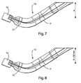
- Figure 7 is an example of embodiment of the modular monolithic packet-shaped trailing arm according to the invention on a suspension without rear-wheel drive and with half-track of value "X".
- Figure 8 is an example of embodiment of the modular monolithic packet-shaped trailing arm according to the invention on a suspension with rear-wheel drive and half-track of value "X+30mm", obtained with a linear modular modification.
- the geometrical shape of the packet-shaped monolithic arm enables reduction in the amount of swarf, with consequent advantage in terms of weights and costs.
- the possibility of varying as desired the height of the volume of the cross section of the arm, optimizing the available space for lay-out constitutes an important opportunity for achieving/optimizing the performance in terms of stiffness in regard to the vertical loads on the suspension; considering that some countries (for example, the U.S.A.) require specific tests for approval on vertical loads, rendering the proposed solution very interesting from this standpoint as compared to any other alternative known solutions.
- the closed section which can vary as desired along the axis of the trailing arm as a function of the configuration offers from a structural standpoint the intrinsic advantage of a stiffness in regard to torsion and bending that is variable along the axis so as to distribute appropriately the stress determined by the conditions of operation of the twist-beam axle.
- an appropriate modelling of the volumes can shift critical states of stress from one area to another of the arm, distributing them or removing them from areas of joining with other objects (for example, the area of coupling of the torsion bar or spring plate).
- This latter feature integrates the concept of linear modularity determined by design to process, with the consequence of being able to intervene at any moment on the process in a fast, effective, simple (linear) way and consequently at a low cost, as a function of the suspension geometries, the suspension behaviour on the vehicle, and the synergies between vehicles and segments of vehicles, eliminating the usually very long times for the modifications necessary for setting-up in the case of known solutions.
Landscapes
- Engineering & Computer Science (AREA)
- Mechanical Engineering (AREA)
- Vehicle Body Suspensions (AREA)
Claims (5)
- Modulare, monolithische, paketförmiger Längslenker für die hintere Verbundlenkerachse eines Kraftfahrzeugs, die aus einer Metallplatte (12) besteht, die gebogen ist, um eine Trichterform zu bilden, und die längs entlang ihren entgegengesetzten Kanten, die einander nach dem Biegen gegenüberliegen, geschweißt (13) ist; wobei die Metallplatte derart geformt ist, dass sie, sobald sie gebogen und geschweißt ist, einen im Wesentlichen kreisförmigen hohlen Abschnitt (17) bildet, der gequetschte Enden hat, von welchen eines (18) mit einer Hülse (14) zum Befestigen der Struktur versehen ist, und das andere Ende (19) mit einer durchgehenden Öffnung (16) zum Befestigen des Antriebsstrangs versehen ist, dadurch gekennzeichnet, dass das andere Ende des Längslenkers eine Verengung der Parallelität zwischen zwei Bauprofilen entlang einer Längsachse hat, das heißt, Maß Y entlang der X-Achse, während sein Maß entlang der dritten Z-Achse in Bezug zu der X-Achse veränderlich ist.
- Längslenker nach Anspruch 1, dadurch gekennzeichnet, dass der Radius (r) der Biegung des einen Endes (18), das mit der Hülse (14) versehen ist, die charakteristische geometrische Lage der vorderen Hülse (14) der rückwärtigen Aufhängung definiert.
- Längslenker nach Anspruch 1, dadurch gekennzeichnet, dass die Lage entlang der Längsachse (Delta x) der rückseitigen Scherung des Längslenkers (12) die Radbasis und Halbspur der Kraftfahrzeugaufhängung bestimmt.
- Längslenker nach Anspruch 1, dadurch gekennzeichnet, dass der Winkel (αsx und αdx) in Bezug zu der Längsachse (X) der hinteren Scherung des Längslenkers (12) die Halbkonvergenz der Kraftfahrzeugaufhängung bestimmt.
- Längslenker nach Anspruch 1, dadurch gekennzeichnet, dass der Winkel (βsx und βdx) in Bezug zu der Senkrechten zu der Längsachse (X) der hinteren Scherung des Längslenkers (12) die Wölbung der Kraftfahrzeugaufhängung bestimmt.
Priority Applications (1)
| Application Number | Priority Date | Filing Date | Title |
|---|---|---|---|
| EP20090425471 EP2327573B1 (de) | 2009-11-18 | 2009-11-18 | Modular monolithischer Längslenker für eine Verbundlenkerachse, verwendbar für Vorder- und Hinterradantrieb |
Applications Claiming Priority (1)
| Application Number | Priority Date | Filing Date | Title |
|---|---|---|---|
| EP20090425471 EP2327573B1 (de) | 2009-11-18 | 2009-11-18 | Modular monolithischer Längslenker für eine Verbundlenkerachse, verwendbar für Vorder- und Hinterradantrieb |
Publications (2)
| Publication Number | Publication Date |
|---|---|
| EP2327573A1 EP2327573A1 (de) | 2011-06-01 |
| EP2327573B1 true EP2327573B1 (de) | 2012-10-17 |
Family
ID=42102015
Family Applications (1)
| Application Number | Title | Priority Date | Filing Date |
|---|---|---|---|
| EP20090425471 Revoked EP2327573B1 (de) | 2009-11-18 | 2009-11-18 | Modular monolithischer Längslenker für eine Verbundlenkerachse, verwendbar für Vorder- und Hinterradantrieb |
Country Status (1)
| Country | Link |
|---|---|
| EP (1) | EP2327573B1 (de) |
Families Citing this family (5)
| Publication number | Priority date | Publication date | Assignee | Title |
|---|---|---|---|---|
| DE102014213098A1 (de) * | 2014-07-07 | 2016-01-07 | Zf Friedrichshafen Ag | Federträgerarm |
| IT201600128281A1 (it) * | 2016-12-19 | 2018-06-19 | Nvengineerings S R L | Metodo di produzione di un braccio oscillante per sospensioni di veicoli. |
| JP6849510B2 (ja) * | 2017-04-04 | 2021-03-24 | 株式会社エフテック | リヤサスペンション用トレーリングアーム |
| CN107599769A (zh) * | 2017-08-21 | 2018-01-19 | 奇瑞汽车股份有限公司 | 一种汽车拖拽臂结构 |
| DE102022111981A1 (de) * | 2022-05-12 | 2023-11-16 | Benteler Automobiltechnik Gmbh | Verbundlenkerachse |
Family Cites Families (5)
| Publication number | Priority date | Publication date | Assignee | Title |
|---|---|---|---|---|
| US5641176A (en) * | 1995-03-31 | 1997-06-24 | Mascotech Tubular Products, Inc. | Process of hydroforming tubular suspension and frame components for vehicles |
| JP3536622B2 (ja) * | 1997-10-13 | 2004-06-14 | トヨタ自動車株式会社 | トーションビーム式サスペンション用トレーリングアーム |
| JP2000335219A (ja) * | 1999-05-28 | 2000-12-05 | Futaba Industrial Co Ltd | トレーリングアーム及びこれを用いたトーションビーム式サスペンション |
| JP2007153254A (ja) * | 2005-12-08 | 2007-06-21 | Toyota Motor Corp | トレーリング・アーム式サスペンション構造 |
| FR2918605A3 (fr) * | 2007-07-12 | 2009-01-16 | Renault Sas | Essieu de vehicule automobile |
-
2009
- 2009-11-18 EP EP20090425471 patent/EP2327573B1/de not_active Revoked
Also Published As
| Publication number | Publication date |
|---|---|
| EP2327573A1 (de) | 2011-06-01 |
Similar Documents
| Publication | Publication Date | Title |
|---|---|---|
| RU2517272C2 (ru) | Поперечина для подвески задней оси в виде изогнутой балки для автотранспортного средства и способ ее изготовления | |
| CA2913353C (en) | Semi-independent suspension system for a low-floor vehicle | |
| EP2995481B1 (de) | Verfahren zum Erhalten eines Arms für mehrgliedrige Aufhängungen von Kraftfahrzeugen und ein Aufhängungslenker | |
| EP2459401B1 (de) | Lasttragender i-träger-kraftfahrzeugaufhängungsarm | |
| EP2327573B1 (de) | Modular monolithischer Längslenker für eine Verbundlenkerachse, verwendbar für Vorder- und Hinterradantrieb | |
| EP3112193B1 (de) | Verfahren zur herstellung eines aufhängungsarms für kraftfahrzeuge und aufhängungsarm | |
| CN104925137B (zh) | 用于车辆的挤压金属副车架 | |
| KR20140135164A (ko) | 차량용 서스펜션 암 | |
| EP2222489B1 (de) | Querträger für eine verbundlenkerachsen-hinterradaufhängung für ein kraftfahrzeug | |
| CA2974205A1 (en) | Vehicle twist axle assembly | |
| CN113784854B (zh) | 悬架总成 | |
| EP2639089B1 (de) | Drehstrahlachse mit Ringelement, das an einen Auslegerarm reibgeschweißt ist | |
| CN112406437A (zh) | 底盘控制臂和用于制造底盘控制臂的方法 | |
| US20180148095A1 (en) | Modular vehicle platform and related methods | |
| WO2011139885A1 (en) | Suspension system for a vehicle and method | |
| CN103448502B (zh) | 一种车辆扭杆梁后悬架 | |
| EP2075146B1 (de) | Verbundlenkerachse und Verfahren zur Herstellung eines Querträgers | |
| CN1644440A (zh) | 将一个整体桥固定在载货汽车框架上的四点臂架 | |
| JP4859833B2 (ja) | 横揺れ防止機能を組み入れた横梁を含む自動車のフレキシブルアクスルと、対応する横梁および自動車の製造方法 | |
| CN116507512A (zh) | 扭转车桥组件 | |
| CN113352836A (zh) | 扭力梁式悬架 | |
| WO2022060648A1 (en) | Frame cross member for battery electric vehicle |
Legal Events
| Date | Code | Title | Description |
|---|---|---|---|
| PUAI | Public reference made under article 153(3) epc to a published international application that has entered the european phase |
Free format text: ORIGINAL CODE: 0009012 |
|
| AK | Designated contracting states |
Kind code of ref document: A1 Designated state(s): AT BE BG CH CY CZ DE DK EE ES FI FR GB GR HR HU IE IS IT LI LT LU LV MC MK MT NL NO PL PT RO SE SI SK SM TR |
|
| AX | Request for extension of the european patent |
Extension state: AL BA RS |
|
| 17P | Request for examination filed |
Effective date: 20111201 |
|
| GRAP | Despatch of communication of intention to grant a patent |
Free format text: ORIGINAL CODE: EPIDOSNIGR1 |
|
| GRAS | Grant fee paid |
Free format text: ORIGINAL CODE: EPIDOSNIGR3 |
|
| GRAA | (expected) grant |
Free format text: ORIGINAL CODE: 0009210 |
|
| AK | Designated contracting states |
Kind code of ref document: B1 Designated state(s): AT BE BG CH CY CZ DE DK EE ES FI FR GB GR HR HU IE IS IT LI LT LU LV MC MK MT NL NO PL PT RO SE SI SK SM TR |
|
| REG | Reference to a national code |
Ref country code: GB Ref legal event code: FG4D |
|
| REG | Reference to a national code |
Ref country code: CH Ref legal event code: EP |
|
| REG | Reference to a national code |
Ref country code: IE Ref legal event code: FG4D |
|
| REG | Reference to a national code |
Ref country code: AT Ref legal event code: REF Ref document number: 579727 Country of ref document: AT Kind code of ref document: T Effective date: 20121115 |
|
| REG | Reference to a national code |
Ref country code: DE Ref legal event code: R096 Ref document number: 602009010468 Country of ref document: DE Effective date: 20121213 |
|
| REG | Reference to a national code |
Ref country code: AT Ref legal event code: MK05 Ref document number: 579727 Country of ref document: AT Kind code of ref document: T Effective date: 20121017 |
|
| REG | Reference to a national code |
Ref country code: NL Ref legal event code: VDEP Effective date: 20121017 |
|
| REG | Reference to a national code |
Ref country code: LT Ref legal event code: MG4D |
|
| PG25 | Lapsed in a contracting state [announced via postgrant information from national office to epo] |
Ref country code: HR Free format text: LAPSE BECAUSE OF FAILURE TO SUBMIT A TRANSLATION OF THE DESCRIPTION OR TO PAY THE FEE WITHIN THE PRESCRIBED TIME-LIMIT Effective date: 20121017 Ref country code: LT Free format text: LAPSE BECAUSE OF FAILURE TO SUBMIT A TRANSLATION OF THE DESCRIPTION OR TO PAY THE FEE WITHIN THE PRESCRIBED TIME-LIMIT Effective date: 20121017 Ref country code: SE Free format text: LAPSE BECAUSE OF FAILURE TO SUBMIT A TRANSLATION OF THE DESCRIPTION OR TO PAY THE FEE WITHIN THE PRESCRIBED TIME-LIMIT Effective date: 20121017 Ref country code: ES Free format text: LAPSE BECAUSE OF FAILURE TO SUBMIT A TRANSLATION OF THE DESCRIPTION OR TO PAY THE FEE WITHIN THE PRESCRIBED TIME-LIMIT Effective date: 20130128 Ref country code: IS Free format text: LAPSE BECAUSE OF FAILURE TO SUBMIT A TRANSLATION OF THE DESCRIPTION OR TO PAY THE FEE WITHIN THE PRESCRIBED TIME-LIMIT Effective date: 20130217 Ref country code: FI Free format text: LAPSE BECAUSE OF FAILURE TO SUBMIT A TRANSLATION OF THE DESCRIPTION OR TO PAY THE FEE WITHIN THE PRESCRIBED TIME-LIMIT Effective date: 20121017 Ref country code: NL Free format text: LAPSE BECAUSE OF FAILURE TO SUBMIT A TRANSLATION OF THE DESCRIPTION OR TO PAY THE FEE WITHIN THE PRESCRIBED TIME-LIMIT Effective date: 20121017 Ref country code: NO Free format text: LAPSE BECAUSE OF FAILURE TO SUBMIT A TRANSLATION OF THE DESCRIPTION OR TO PAY THE FEE WITHIN THE PRESCRIBED TIME-LIMIT Effective date: 20130117 |
|
| PG25 | Lapsed in a contracting state [announced via postgrant information from national office to epo] |
Ref country code: PL Free format text: LAPSE BECAUSE OF FAILURE TO SUBMIT A TRANSLATION OF THE DESCRIPTION OR TO PAY THE FEE WITHIN THE PRESCRIBED TIME-LIMIT Effective date: 20121017 Ref country code: BE Free format text: LAPSE BECAUSE OF FAILURE TO SUBMIT A TRANSLATION OF THE DESCRIPTION OR TO PAY THE FEE WITHIN THE PRESCRIBED TIME-LIMIT Effective date: 20121017 Ref country code: SI Free format text: LAPSE BECAUSE OF FAILURE TO SUBMIT A TRANSLATION OF THE DESCRIPTION OR TO PAY THE FEE WITHIN THE PRESCRIBED TIME-LIMIT Effective date: 20121017 Ref country code: PT Free format text: LAPSE BECAUSE OF FAILURE TO SUBMIT A TRANSLATION OF THE DESCRIPTION OR TO PAY THE FEE WITHIN THE PRESCRIBED TIME-LIMIT Effective date: 20130218 Ref country code: LV Free format text: LAPSE BECAUSE OF FAILURE TO SUBMIT A TRANSLATION OF THE DESCRIPTION OR TO PAY THE FEE WITHIN THE PRESCRIBED TIME-LIMIT Effective date: 20121017 Ref country code: GR Free format text: LAPSE BECAUSE OF FAILURE TO SUBMIT A TRANSLATION OF THE DESCRIPTION OR TO PAY THE FEE WITHIN THE PRESCRIBED TIME-LIMIT Effective date: 20130118 |
|
| PG25 | Lapsed in a contracting state [announced via postgrant information from national office to epo] |
Ref country code: AT Free format text: LAPSE BECAUSE OF FAILURE TO SUBMIT A TRANSLATION OF THE DESCRIPTION OR TO PAY THE FEE WITHIN THE PRESCRIBED TIME-LIMIT Effective date: 20121017 |
|
| PLBI | Opposition filed |
Free format text: ORIGINAL CODE: 0009260 |
|
| PG25 | Lapsed in a contracting state [announced via postgrant information from national office to epo] |
Ref country code: DK Free format text: LAPSE BECAUSE OF FAILURE TO SUBMIT A TRANSLATION OF THE DESCRIPTION OR TO PAY THE FEE WITHIN THE PRESCRIBED TIME-LIMIT Effective date: 20121017 Ref country code: BG Free format text: LAPSE BECAUSE OF FAILURE TO SUBMIT A TRANSLATION OF THE DESCRIPTION OR TO PAY THE FEE WITHIN THE PRESCRIBED TIME-LIMIT Effective date: 20130117 Ref country code: CZ Free format text: LAPSE BECAUSE OF FAILURE TO SUBMIT A TRANSLATION OF THE DESCRIPTION OR TO PAY THE FEE WITHIN THE PRESCRIBED TIME-LIMIT Effective date: 20121017 Ref country code: EE Free format text: LAPSE BECAUSE OF FAILURE TO SUBMIT A TRANSLATION OF THE DESCRIPTION OR TO PAY THE FEE WITHIN THE PRESCRIBED TIME-LIMIT Effective date: 20121017 Ref country code: SK Free format text: LAPSE BECAUSE OF FAILURE TO SUBMIT A TRANSLATION OF THE DESCRIPTION OR TO PAY THE FEE WITHIN THE PRESCRIBED TIME-LIMIT Effective date: 20121017 |
|
| 26 | Opposition filed |
Opponent name: BENTELER AUTOMOBILTECHNIK GMBH Effective date: 20130703 |
|
| REG | Reference to a national code |
Ref country code: IE Ref legal event code: MM4A |
|
| PLAX | Notice of opposition and request to file observation + time limit sent |
Free format text: ORIGINAL CODE: EPIDOSNOBS2 |
|
| PG25 | Lapsed in a contracting state [announced via postgrant information from national office to epo] |
Ref country code: RO Free format text: LAPSE BECAUSE OF FAILURE TO SUBMIT A TRANSLATION OF THE DESCRIPTION OR TO PAY THE FEE WITHIN THE PRESCRIBED TIME-LIMIT Effective date: 20121017 |
|
| REG | Reference to a national code |
Ref country code: DE Ref legal event code: R026 Ref document number: 602009010468 Country of ref document: DE Effective date: 20130703 |
|
| PG25 | Lapsed in a contracting state [announced via postgrant information from national office to epo] |
Ref country code: IE Free format text: LAPSE BECAUSE OF NON-PAYMENT OF DUE FEES Effective date: 20121118 |
|
| PG25 | Lapsed in a contracting state [announced via postgrant information from national office to epo] |
Ref country code: CY Free format text: LAPSE BECAUSE OF FAILURE TO SUBMIT A TRANSLATION OF THE DESCRIPTION OR TO PAY THE FEE WITHIN THE PRESCRIBED TIME-LIMIT Effective date: 20121017 Ref country code: MT Free format text: LAPSE BECAUSE OF FAILURE TO SUBMIT A TRANSLATION OF THE DESCRIPTION OR TO PAY THE FEE WITHIN THE PRESCRIBED TIME-LIMIT Effective date: 20121017 |
|
| PGFP | Annual fee paid to national office [announced via postgrant information from national office to epo] |
Ref country code: DE Payment date: 20131113 Year of fee payment: 5 Ref country code: FR Payment date: 20131108 Year of fee payment: 5 |
|
| PG25 | Lapsed in a contracting state [announced via postgrant information from national office to epo] |
Ref country code: TR Free format text: LAPSE BECAUSE OF FAILURE TO SUBMIT A TRANSLATION OF THE DESCRIPTION OR TO PAY THE FEE WITHIN THE PRESCRIBED TIME-LIMIT Effective date: 20121017 Ref country code: MC Free format text: LAPSE BECAUSE OF NON-PAYMENT OF DUE FEES Effective date: 20121130 |
|
| PG25 | Lapsed in a contracting state [announced via postgrant information from national office to epo] |
Ref country code: LU Free format text: LAPSE BECAUSE OF NON-PAYMENT OF DUE FEES Effective date: 20121118 Ref country code: SM Free format text: LAPSE BECAUSE OF FAILURE TO SUBMIT A TRANSLATION OF THE DESCRIPTION OR TO PAY THE FEE WITHIN THE PRESCRIBED TIME-LIMIT Effective date: 20121017 |
|
| REG | Reference to a national code |
Ref country code: CH Ref legal event code: PL |
|
| GBPC | Gb: european patent ceased through non-payment of renewal fee |
Effective date: 20131118 |
|
| PG25 | Lapsed in a contracting state [announced via postgrant information from national office to epo] |
Ref country code: LI Free format text: LAPSE BECAUSE OF NON-PAYMENT OF DUE FEES Effective date: 20131130 Ref country code: HU Free format text: LAPSE BECAUSE OF FAILURE TO SUBMIT A TRANSLATION OF THE DESCRIPTION OR TO PAY THE FEE WITHIN THE PRESCRIBED TIME-LIMIT Effective date: 20091118 Ref country code: CH Free format text: LAPSE BECAUSE OF NON-PAYMENT OF DUE FEES Effective date: 20131130 |
|
| PG25 | Lapsed in a contracting state [announced via postgrant information from national office to epo] |
Ref country code: IT Free format text: LAPSE BECAUSE OF NON-PAYMENT OF DUE FEES Effective date: 20131118 |
|
| PG25 | Lapsed in a contracting state [announced via postgrant information from national office to epo] |
Ref country code: GB Free format text: LAPSE BECAUSE OF NON-PAYMENT OF DUE FEES Effective date: 20131118 |
|
| RDAF | Communication despatched that patent is revoked |
Free format text: ORIGINAL CODE: EPIDOSNREV1 |
|
| REG | Reference to a national code |
Ref country code: DE Ref legal event code: R103 Ref document number: 602009010468 Country of ref document: DE Ref country code: DE Ref legal event code: R064 Ref document number: 602009010468 Country of ref document: DE |
|
| RDAG | Patent revoked |
Free format text: ORIGINAL CODE: 0009271 |
|
| STAA | Information on the status of an ep patent application or granted ep patent |
Free format text: STATUS: PATENT REVOKED |
|
| 27W | Patent revoked |
Effective date: 20150119 |
|
| REG | Reference to a national code |
Ref country code: DE Ref legal event code: R107 Ref document number: 602009010468 Country of ref document: DE |