EP2327646B1 - In einem Abzweig einer Transportbahn für Laborproben in einem analytischen Labor angeordnete Weiche - Google Patents
In einem Abzweig einer Transportbahn für Laborproben in einem analytischen Labor angeordnete Weiche Download PDFInfo
- Publication number
- EP2327646B1 EP2327646B1 EP09177226A EP09177226A EP2327646B1 EP 2327646 B1 EP2327646 B1 EP 2327646B1 EP 09177226 A EP09177226 A EP 09177226A EP 09177226 A EP09177226 A EP 09177226A EP 2327646 B1 EP2327646 B1 EP 2327646B1
- Authority
- EP
- European Patent Office
- Prior art keywords
- sample holder
- branch
- transport track
- adjusting wheel
- magnet
- Prior art date
- Legal status (The legal status is an assumption and is not a legal conclusion. Google has not performed a legal analysis and makes no representation as to the accuracy of the status listed.)
- Active
Links
Images
Classifications
-
- B—PERFORMING OPERATIONS; TRANSPORTING
- B65—CONVEYING; PACKING; STORING; HANDLING THIN OR FILAMENTARY MATERIAL
- B65G—TRANSPORT OR STORAGE DEVICES, e.g. CONVEYORS FOR LOADING OR TIPPING, SHOP CONVEYOR SYSTEMS OR PNEUMATIC TUBE CONVEYORS
- B65G47/00—Article or material-handling devices associated with conveyors; Methods employing such devices
- B65G47/74—Feeding, transfer, or discharging devices of particular kinds or types
- B65G47/84—Star-shaped wheels or devices having endless travelling belts or chains, the wheels or devices being equipped with article-engaging elements
- B65G47/846—Star-shaped wheels or wheels equipped with article-engaging elements
- B65G47/848—Star-shaped wheels or wheels equipped with article-engaging elements the article-engaging elements being suction or magnetic means
-
- G—PHYSICS
- G01—MEASURING; TESTING
- G01N—INVESTIGATING OR ANALYSING MATERIALS BY DETERMINING THEIR CHEMICAL OR PHYSICAL PROPERTIES
- G01N35/00—Automatic analysis not limited to methods or materials provided for in any single one of groups G01N1/00 - G01N33/00; Handling materials therefor
- G01N35/02—Automatic analysis not limited to methods or materials provided for in any single one of groups G01N1/00 - G01N33/00; Handling materials therefor using a plurality of sample containers moved by a conveyor system past one or more treatment or analysis stations
- G01N35/04—Details of the conveyor system
-
- B—PERFORMING OPERATIONS; TRANSPORTING
- B65—CONVEYING; PACKING; STORING; HANDLING THIN OR FILAMENTARY MATERIAL
- B65G—TRANSPORT OR STORAGE DEVICES, e.g. CONVEYORS FOR LOADING OR TIPPING, SHOP CONVEYOR SYSTEMS OR PNEUMATIC TUBE CONVEYORS
- B65G2201/00—Indexing codes relating to handling devices, e.g. conveyors, characterised by the type of product or load being conveyed or handled
- B65G2201/02—Articles
- B65G2201/0235—Containers
- B65G2201/0261—Puck as article support
-
- G—PHYSICS
- G01—MEASURING; TESTING
- G01N—INVESTIGATING OR ANALYSING MATERIALS BY DETERMINING THEIR CHEMICAL OR PHYSICAL PROPERTIES
- G01N35/00—Automatic analysis not limited to methods or materials provided for in any single one of groups G01N1/00 - G01N33/00; Handling materials therefor
- G01N35/02—Automatic analysis not limited to methods or materials provided for in any single one of groups G01N1/00 - G01N33/00; Handling materials therefor using a plurality of sample containers moved by a conveyor system past one or more treatment or analysis stations
- G01N35/04—Details of the conveyor system
- G01N2035/0401—Sample carriers, cuvettes or reaction vessels
- G01N2035/0406—Individual bottles or tubes
-
- G—PHYSICS
- G01—MEASURING; TESTING
- G01N—INVESTIGATING OR ANALYSING MATERIALS BY DETERMINING THEIR CHEMICAL OR PHYSICAL PROPERTIES
- G01N35/00—Automatic analysis not limited to methods or materials provided for in any single one of groups G01N1/00 - G01N33/00; Handling materials therefor
- G01N35/02—Automatic analysis not limited to methods or materials provided for in any single one of groups G01N1/00 - G01N33/00; Handling materials therefor using a plurality of sample containers moved by a conveyor system past one or more treatment or analysis stations
- G01N35/04—Details of the conveyor system
- G01N2035/0474—Details of actuating means for conveyors or pipettes
- G01N2035/0477—Magnetic
Definitions
- Conveyor systems have been used to cope with the flow of material in larger analytical laboratories for several years. These systems are capable of directing large quantities of specimens individually in different orders to different targets. For this purpose, turnouts are required in the conveyor system, which sort individual samples out of the flow of material and control them in branches or on other conveyor tracks.
- sliding switches are used to move a material carrier laterally from one conveyor track to another. This is for example in the DE 44 34 714 A1 shown (see there Fig. 1 , Reference numeral 28).
- the sliding switch has the disadvantage that the slide blocks the conveyor track for subsequent material carrier in the separation of a material carrier and takes time to retire again.
- the material undergoes a braking acceleration in the direction of travel, a lateral acceleration and Braking and then an acceleration in the new direction of travel.
- the solution through a disc is demanding space, since the disc has to reach across several conveyor tracks.
- Trustnde material carriers can not drive unhindered through them, but must always be actively implemented.
- the processing of the material carrier in the switch is time-consuming, and it is stopped each material carrier, undergoes a spin and then an acceleration in the new direction.
- the invention has for its object to divide a stream of material arranged on sample holders laboratory samples in a switch area as quickly as possible.
- the aim is to create a switch mechanism that takes up as little space as possible in order to increase the flexibility of the conveyor system and to reduce space requirements.
- the branch is arranged as a control of the switch on its circumference at least one magnet bearing, drivable for rotation thumb wheel.
- this arrangement takes place in such a way that during a rotation of the adjusting wheel of the magnet detects a magnetic portion of the sample holder and the sample holder is transferred to the branch.
- the holding portion of the sample holder may either be a magnet itself, but is preferably made of a ferromagnetic material (eg, an iron sheet).
- the force of the magnet on the holding portion is dimensioned so that a safe stripping of the holding portion of the magnet after completion transfer to the branch can be made, or the magnet on the thumbwheel itself is switched off, especially in the form of an electromagnet (see. Claim 2).
- the thumbwheel is arranged next to the transport path and forms with a peripheral portion in an area in which the lateral guide wall of the transport path is omitted, an extension of this guide section.
- the magnet is activated or selectively positioned to detect the holding portion of the sample holder when it is to be transferred to the branch. If the sample holder is to be transported further on the branch of the transport path and not transferred to the branch, the setting wheel can be positioned at a corresponding angle in which no magnet points in the direction of the old section of a passing sample holder. In this position, the setting wheel does not affect the direction of travel of the sample holder, but serves as an extension of the lateral guidance.
- the switch is arranged outside the actual movement path of the sample holder, so that it does not hinder the further transport of subsequent sample holder, thus allowing a speedy "wiring" of the switch without acting as in the art as a "bottleneck” for subsequent sample holder.
- the switch is designed so that the thumbwheel is actively driven by its own drive to form an "active switch", is driven by the active drive of the sample holder in the branch.
- the switch on a control by means of which the setting wheel can be activated and driven.
- This control can be connected to a sensor for detecting the position of a sample holder entering the region of the switch, as may be provided according to claim 4.
- a sensor for position detection allows by an early and accurate detection of the position of a approaching sample holder an exact tuning of the switch and positioning of the setting wheel for optimal detection of the holding portion of the sample holder (see claim 6).
- the sensor for position detection for example, a light barrier, a proximity sensor, or a Hall sensor included, but also be equipped with all other conceivable sensor elements for position detection.
- the switch which is connected to the controller and set up to recognize on the sample holders, these individualizing identifiers.
- the sample holder can be detected and it can be decided whether the laboratory sample arranged thereon is to be transferred to the branch or whether it is to be guided along the main direction of the transport path.
- the drive of the setting wheel is set so that when detecting a sample holder by the magnet, the rotational speed of the adjusting wheel of a flow velocity in the Transport path corresponds, more precisely, a web speed of the rotating magnet corresponds to the flow velocity.
- the drive of the setting wheel is set as specified in claim 9. Accordingly, the setting wheel of the switch is correspondingly reduced uniformly in its rotational speed in order to prevent an abrupt deceleration during stripping of the holding portion of the magnet so and here to provide a sliding as possible transition of the movements.
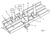
- Fig. 1 which shows a schematic and by no means true to scale representation of an embodiment of a transport path according to the invention
- two conveyor lines are arranged side by side 1.
- the conveyor line 1 arranged on the left in the transport direction or in the illustration above is the main transport direction, and the lower section 1 shown on the right in the transport direction represents a branch.
- sample holders 6, 7, 8 In the conveyor lines 1 run laterally on sidewalls arranged conveyor belt 2, which are driven and on which sample holders 6, 7, 8 sit and transported, in which sample containers 3 are held with laboratory samples. Examples of such laboratory samples may be urine samples, blood samples, but also solid samples or liquid-dissolved samples for laboratory analysis.
- the sample holders 6, 7, 8 have a substantially square base body with rounded corners. On all four lateral longitudinal sides of the sample holder iron plates are arranged centrally, which form a magnetic holding portion.
- a control body in the form of a setting wheel 4, the equi-angularly distributed along its circumference (at an angular distance of 120 °) has a total of three magnets 5.
- the thumbwheel 4 is arranged rotatable about a central axis, wherein a motor drive 9 is provided for direct driving of the wheel 4.
- a sample holder 6 is located in the region of the switch, wherein the adjusting wheel 4 has been rotated into an angular position in which one of the magnets 5 acts on a holding section of the sample holder 6 opposite thereto.
- the drive 9 now moves the setting wheel 4 synchronized with a peripheral speed corresponding to the speed of the conveyor belt 2 and thus pulls the sample holder 6 together with the sample vessel 3 arranged thereon along the direction of the arrow 10 through the opening in the lateral guide into the branch, ie In this conveyor section there is already a previously sorted sample holder 7.
- the branch conveyor belts 2 run in the new conveying direction and thus ensure the removal of the sample holder 7 and the sample holder 6, after this has been transferred to the branch.
- the magnet 5 is released from the holding section on the sample holder 6, so that the transition to the removal movement can be controlled by the circulating conveyor belt 2 in the branch .
- the rotational speed of the adjusting wheel 4 is reduced to lateral accelerations in the transfer of the sample holder 6 for removal into the branch to minimize.
- the setting wheel 4 is repositioned to transfer a subsequent further sample holder 8 in the branch (magnet 5 in the direction of the holding portion of the passing sample holder aligned) or to let the following sample holder 8 in the main transport direction continue (position of the setting wheel 4 so in that no magnet points in the direction of the holding section of the sample holder 8.
- the switch sensor unit which is located upstream of the switch in the region of the sample holder 8 and once a position detection of an approaching sample holder 8, on the other hand, an evaluation for detecting the individualizing identifier of the sample holder 8 is used.
- This unit is connected to a control, also not shown, which in turn controls the motor drive 9 of the adjusting wheel 4 to position this adjusting wheel 4 and to synchronize in its run with the drive speed of the conveyor belt 2 in the conveyor section 1 shown in the figure above so as to ensure a safe detection and transfer of a sample holder in the branch.
- the individualized recognition of the sample holder can be carried out in known manner e.g. with barcodes, through data matrix codes or via radio frequency identification (RF-ID).
- the controller may be formed in particular in the form of a microcomputer.
Landscapes
- Engineering & Computer Science (AREA)
- Mechanical Engineering (AREA)
- Physics & Mathematics (AREA)
- Health & Medical Sciences (AREA)
- Life Sciences & Earth Sciences (AREA)
- Chemical & Material Sciences (AREA)
- Analytical Chemistry (AREA)
- Biochemistry (AREA)
- General Health & Medical Sciences (AREA)
- General Physics & Mathematics (AREA)
- Immunology (AREA)
- Pathology (AREA)
- Automatic Analysis And Handling Materials Therefor (AREA)
- Non-Mechanical Conveyors (AREA)
Description
- Zur Bewältigung des Materialflusses in größeren analytischen Laboratorien haben seit einigen Jahren Fördersysteme Einzug gehalten. Diese Systeme sind in der Lage, große Mengen an Untersuchungsmaterial individuell in unterschiedlicher Reihenfolge an verschiedenste Ziele zu lenken. Hierzu werden im Fördersystem Weichen benötigt, die einzelne Proben aus dem Materialstrom heraus sortieren und in Abzweige bzw. auf andere Förderbahnen steuern.
- Entsprechend dem Stand der Technik werden dazu Schiebeweichen verwendet, die einen Materialträger seitlich von einer Förderbahn auf eine andere verschieben. Dies ist z.B. in der
DE 44 34 714 A1 gezeigt (vgl. dortFig. 1 , Bezugsziffer 28). - Eine andere Lösung ist in der
DE 43 29 078 A1 beschrieben. Dort ist eine Scheibe vorgesehen, die an ihrem äußeren Umfang Ausnehmungen aufweist, in die runde Materialträger hineinfahren. Die Scheibe befördert anschließend den Materialträger durch Drehen über eine bestimmte Förderbahn, die den Materialträger weitertransportiert (OffenlegungsschriftDE 43 29 078 A1 ). - Die Schiebeweiche hat den Nachteil, dass der Schieber bei der Aussonderung eines Materialträgers die Förderbahn für nachfolgende Materialträger blockiert und Zeit benötigt, um sich wieder zurückzuziehen. Außerdem erfährt das Material eine Bremsbeschleunigung in Fahrtrichtung, eine seitliche Beschleunigung und Bremsung und anschließend eine Beschleunigung in der neuen Fahrtrichtung. Die Lösung durch eine Scheibe ist Raum fordernd, da die Scheibe über mehrere Förderbahnen hinweg reichen muss. Nicht auszusteuernde Materialträger können nicht ungehindert durch sie hindurch fahren, sondern müssen immer aktiv umgesetzt werden. Dadurch ist die Verarbeitung der Materialträger in der Weiche zeitaufwendig, und es wird jeder Materialträger gestoppt, erfährt eine Drehbeschleunigung und anschließend eine Beschleunigung in der neuen Fahrtrichtung.
- Eine weitere, dem Oberbegriff des Anspruchs 1 entsprechende Konstruktionsmöglichkeit ist in der
US 2005/0207937 A1 offenbart. Dort ist eine Weiche für das Sortieren von in Probenhaltern angeordneten Laborproben gezeigt, die zum Überführen einer Probe ein rotierendes Rad mit umfangsseitig angeordneten Magneten aufweist, welche in der Höhe so positioniert sind, dass sie an einem seitlich an dem Probenhalter angeordneten magnetischen Abschnitt angreifen können, um den Probenhalter dann mitzunehmen und auf eine Abzweigbahn zu überführen. Um den Überführungsprozess auszulösen, fahren bei dieser Konstruktion Umlenkarme in die Transportbahn, die die dort laufenden Probenhalter aus dem Geradeauslauf, in dem sie das mit Magneten bestückte Rad unbeeinflusst passieren würden, auslenken und gegen die Umfangsfläche des Magnetrades drücken, wo der Probenhalter dann erfasst und anschließend durch eine Unterbrechung in der seitlichen Führungswand überführt wird. Diese Lösung benötigt die zusätzlichen Elemente der Umlenkarme, die entsprechenden Montageraum benötigen, die Fördergeschwindigkeit in der Transportbahn beschränken und eine zusätzliche Störanfälligkeit bedingen. - Der Erfindung liegt die Aufgabe zugrunde, einen Materialstrom aus auf Probenhaltern angeordneten Laborproben in einem Weichenbereich möglichst zügig aufzuteilen. Darüber hinaus ist es das Ziel, eine Weichenmechanik zu schaffen, die möglichst wenig Raum beansprucht, um die Flexibilität des Fördersystems zu erhöhen und den Platzbedarf zu verringern.
- Dabei sollen bevorzugt auch unnötige Beschleunigungen der Laborproben vermieden werden, die zu einer unerwünschten Vermischung des Probeninhaltes, beispielsweise bei zentrifugierten Blutproben, führen können. Auszusteuernde Laborproben sollen bevorzugt ebenso mit minimal möglichen Beschleunigungen aus dem Probenstrom herausgegriffen und auf eine andere Förderstrecke gesteuert werden.
- Die Aufgabe wird erfindungsgemäß gelöst durch eine Transportbahn mit den Merkmalen des Anspruchs 1. Vorteilhafte Weiterbildungen dieser Transportbahn, die insbesondere die oben als bevorzugt zu lösenden Aufgabenaspekte und auch andere Aufgaben lösen, sind in den abhängigen Ansprüchen 2 bis 9 angegeben.
- Gemäß der Erfindung ist dem Abzweig als Steuerelement der Weiche ein an seinem Umfang wenigstens einen Magneten tragendes, zur Rotation antreibbares Stellrad angeordnet. Dabei erfolgt diese Anordnung solchermaßen, dass bei einer Rotation des Stellrades der Magnet einen magnetischen Abschnitt des Probenhalters erfasst und der Probenhalter so in den Abzweig überführt wird. Der Halteabschnitt des Probenhalters kann entweder selbst ein Magnet sein, ist jedoch bevorzugt aus einem ferromagnetischen Material (z.B. einem Eisenblech). Dabei ist entweder die Kraft des Magneten auf den Halteabschnitt so bemessen, dass ein gefahrloses Abstreifen des Halteabschnittes von dem Magneten nach vollendeter Überführung in den Abzweig erfolgen kann, oder der Magnet an dem Stellrad ist selbst abschaltbar gestaltet, insbesondere in Form eines Elektromagneten (vgl. Anspruch 2). Das Stellrad ist dabei neben der Transportbahn angeordnet und bildet mit einem Umfangsabschnitt in einem Bereich, in dem die seitliche Führungswand der Transportbahn fortgelassen ist, eine Verlängerung dieses Führungsabschnittes. Dort wird der Magnet aktiviert bzw. gezielt positioniert, um den Halteabschnitt des Probenhalters zu erfassen, wenn dieser in den Abzweig überführt werden soll. Soll der Probenhalter auf dem Abzweig der Transportbahn weiter transportiert und nicht in den Abzweig überführt werden, so kann das Stellrad in einem entsprechenden Winkel positioniert werden, in dem kein Magnet in Richtung des alten Abschnittes eines vorbeifahrenden Probenhalters weist. In dieser Stellung beeinflusst das Stellrad die Fahrtrichtung des Probenhalters nicht, dient vielmehr als Verlängerung der seitlichen Führung.
- Dies erlaubt eine besonders kompakte Bauweise der Weiche. Denn das Stellrad kann entsprechend klein dimensioniert werden.
- Die Weiche ist außerhalb des eigentlichen Bewegungspfades des Probenhalters angeordnet, so dass er den Weitertransport nachfolgender Probenhalter nicht behindert, mithin eine zügige "Beschaltung" der Weiche erlaubt, ohne wie im Stand der Technik als "Nadelöhr" für nachfolgende Probenhalter zu wirken.
- Insbesondere ist die Weiche so ausgebildet, dass das Stellrad über einen eigenen Antrieb aktiv angetrieben wird, um eine "Aktivweiche" auszubilden, mit der durch den aktiven Antrieb der Probenhalter in den Abzweig gefahren wird.
- Mit Vorteil weist die Weiche eine Steuerung auf, mittels derer das Stellrad aktiviert und angetrieben werden kann. Diese Steuerung kann mit einem Sensor zur Positionserkennung eines in den Bereich der Weiche einfahrenden Probenhalters verbunden sein, wie er gemäß Anspruch 4 vorgesehen sein kann. Ein Sensor zur Positionserkennung erlaubt durch ein frühzeitiges und genaues Erkennen der Position eines heranfahrenden Probenhalters eine exakte Abstimmung der Weiche und Positionierung des Stellrades zum optimalen Erfassen des Halteabschnittes des Probenhalters (vgl. Anspruch 6). Der Sensor zur Positionserkennung kann beispielsweise eine Lichtschranke, einen Nährungsinitiator, oder einen Hallsensor enthalten, aber auch mit allen anderen denkbaren Sensorelementen zur Positionserfassung ausgestattet sein.
- Für die geforderte weitgehende Automatisierung des Transportsystems bzw. der Transportbahn ist es von Vorteil, wenn im Bereich der Weiche eine Auswerteeinrichtung vorgesehen ist, die mit der Steuerung verbunden und zur Erkennung von auf den Probenhaltern angebrachten, diese individualisierenden Kennungen eingerichtet ist. So kann bei einer Näherung eines Probenhalters an die Weiche der Probenhalter erkannt und es kann entschieden werden, ob die auf diesem angeordnete Laborprobe in den Abzweig zu überführen ist oder aber den weiteren Weg entlang der Hauptrichtung der Transportbahn geführt werden soll.
- Für die gemäß einem Unteraspekt der Aufgabe der Erfindung anzustrebende, schonende Behandlung der Proben im Bereich der Weiche, ist es von Vorteil, wenn der Antrieb des Stellrades so eingerichtet ist, dass beim Erfassen eines Probenhalters durch den Magneten die Rotationsgeschwindigkeit des Stellrades einer Fließgeschwindigkeit in der Transportbahn entspricht, genauer eine Bahngeschwindigkeit des rotierenden Magnet der Fließgeschwindigkeit entspricht. Durch diese Maßnahme werden bei den Weichensystemen gemäß dem Stand der Technik auftretende Querbeschleunigungen bzw. das abrupte Bremsen und Beschleunigen der Proben verhindert. Eine weitere Verbesserung der schonenden Behandlung der Proben ergibt sich, wenn der Antrieb des Stellrades wie in Anspruch 9 angegeben eingerichtet ist. Demgemäß wird das Stellrad der Weiche in seiner Rotationsgeschwindigkeit entsprechend gleichmäßig verringert, um eine abrupte Abbremsung beim Abstreifen des Halteabschnittes von dem Magneten so verhindert und auch hier einen möglichst gleitenden Übergang der Bewegungen zu schaffen.
- Weitere Vorteile und Merkmale ergeben sich aus der nachfolgenden Beschreibung eines Ausführungsbeispiels anhand der beigefügten Figur. Es zeigt:
- Fig. 1
- einen Ausschnitt eines Transport- bzw. Fördersystems für Laborproben mit einer erfindungsgemäßen Weiche in dreidimensionaler Ansicht von oben.
- In
Fig. 1 , die eine schematische und keinesfalls maßstabsgerechte Darstellung eines Ausführungsbeispiels einer erfindungsgemäßen Transportbahn zeigt, sind zwei nebeneinander angeordnete Förderstrecken mit 1 bezeichnet. Die in der Figur in Transportrichtung links bzw. in der Darstellung oberhalb angeordnete Förderstrecke 1 ist dabei die Haupttransportrichtung, die in Transportrichtung rechts dargestellte, in der Figur untere Strecke 1 stellt einen Abzweig dar. - In den Förderstrecken 1 laufen seitlich an Seitenwänden angeordnete Förderriemen 2 um, die angetrieben sind und auf denen Probenhalter 6, 7, 8 aufsitzen und transportiert werden, in denen wiederum Probengefäße 3 mit Laborproben gehalten sind. Beispiele für solche Laborproben können sein Urinproben, Blutproben, aber auch feste Proben oder in Flüssigkeit aufgelöste Proben zur labortechnischen Analyse. Die Probenhalter 6, 7, 8 haben einen im Wesentlichen quadratischen Grundkörper mit abgerundeten Ecken. An allen vier seitlichen Längsseiten der Probenhalter sind mittig Eisenbleche angeordnet, die einen magnetischen Halteabschnitt bilden.
- In der Weiche befindet sich ferner ein Stellkörper in Form eines Stellrades 4, das entlang seines Umfanges gleichwinklig verteilt (in einem Winkelabstand von 120°) insgesamt drei Magnete 5 aufweist. Das Stellrad 4 ist um eine mittelsenkrechte Achse rotierbar angeordnet, wobei ein motorischer Antrieb 9 zum direkten Antreiben des Rades 4 vorgesehen ist.
- In der in
Fig. 1 gezeigten Situation befindet sich ein Probenhalter 6 im Bereich der Weiche, wobei das Stellrad 4 in eine Winkelposition gedreht worden ist, in welcher einer der Magneten 5 an einem diesem gegenüberliegenden Halteabschnitt des Probenhalters 6 angreift. Der Antrieb 9 bewegt nun das Stellrad 4 synchronisiert mit einer Umfangsgeschwindigkeit, die der Geschwindigkeit der Förderriemen 2 entspricht und zieht so den Probenhalter 6 mitsamt dem darauf angeordneten Probengefäß 3 entlang der Richtung des Pfeils 10 durch die Öffnung in der seitlichen Führung in den Abzweig, also die in Förderrichtung rechts gelegene, in der Figur unten dargestellte Förderstrecke 1. In dieser Förderstrecke befindet sich bereits ein zuvor aussortierter Probenhalter 7. In dem Abzweig laufen die Förderriemen 2 in der neuen Förderrichtung und besorgen so den Abtransport des Probenhalters 7 sowie des Probenhalters 6, nach dem dieser in den Abzweig überführt worden ist. - Durch weitere Rotation des Stellrades 4, wenn der Probenhalter 6 gegen die untere Seitenwand des Abzweiges stößt, wird der Magnet 5 von dem Halteabschnitt an dem Probenhalter 6 gelöst, so dass der Übergang in die Abtransportbewegung gesteuert durch die umlaufenden Förderriemen 2 in dem Abzweig erfolgen kann. Während des Überführens des Probenhalters 6 in den Abzweig wird die Rotationsgeschwindigkeit des Stellrades 4 verringert, um Querbeschleunigungen bei der Überführung des Probenhalters 6 zum Abtransport in den Abzweig zu minimieren. Im Anschluss wird das Stellrad 4 erneut positioniert, um einen nachfolgenden weiteren Probenhalter 8 in den Abzweig zu überführen (Magnet 5 in Richtung des Halteabschnittes des vorbeifahrenden Probenhalters ausgerichtet) oder um den nachfolgenden Probenhalter 8 in der Haupttransportrichtung weiterfahren zu lassen (Position des Stellrades 4 so, dass kein Magnet in Richtung des Halteabschnittes des Probenhalters 8 weist.
- Nicht näher gezeigt ist eine in der Weiche angeordnete Sensoreinheit, die stromauf der Weiche im Bereich des Probenhalters 8 gelegen ist und einmal einer Positionserkennung eines sich nähernden Probenhalters 8, zum anderen einer Auswertung zur Erkennung der individualisierenden Kennung des Probenhalters 8 dient. Diese Einheit ist mit einer ebenfalls nicht gezeigten Steuerung verbunden, die wiederum den motorischen Antrieb 9 des Stellrades 4 ansteuert, um dieses Stellrad 4 entsprechend zu positionieren und in seinem Lauf mit der Antriebsgeschwindigkeit der Förderriemen 2 in der in der Figur oben dargestellten Förderstrecke 1 zu synchronisieren, um so ein sicheres Erfassen und Überführen eines Probenhalters in den Abzweig zu gewährleisten.
- Die individualisierte Erkennung des Probenhalters kann in bekannter Weise z.B. mit Barcodes, durch Datamatrixcodes oder mittels Radiofrequenz-Identifikation (RF-ID) erfolgen. Die Steuerung kann insbesondere in Form eines Mikrocomputers gebildet sein.
- Das hier gezeigte Ausführungsbeispiel ist nicht beschränkend, sondern dient lediglich der Erläuterung der Erfindung, die in den nachfolgenden Ansprüchen in ihrer Allgemeinheit bestimmt ist.
-
- 1
- Förderstrecke
- 2
- Förderriemen
- 3
- Probengefäß
- 4
- Stellrad
- 5
- Magnet
- 6
- Probenhalter
- 7
- Probenhalter
- 8
- Probenhalter
- 9
- motorischer Antrieb
- 10
- Pfeil
Claims (9)
- Eine Transportbahn (1) für Laborproben in einem analytischen Labor mit einem Abzweig und mit einer im Abzweig angeordneten Weiche zur Steuerung eines Materialflusses der auf in einem Halteabschnitt mit einem magnetischen Material versehenen Probenhaltern (6, 7, 8) in der Transportbahn (1) geführten Laborproben, wobei in dem Abzweig ein zur Rotation antreibbarer Stellkörper in Form eines Stellrades (4) mit wenigstens einem an seinem Umfang angeordneten Magneten (5) derart angeordnet ist, dass bei einer Rotation des Stellrades (4) der Magnet (5) den Halteabschnitt des Probenhalters (6, 7, 8) erfasst und der Probenhalter (6, 7, 8) so in den Abzweig überführt wird, wobei das Stellrad (4) in einem Abschnitt, in welchem für eine Überführung des Probenhalters (6, 7, 8) in den Abzweig eine seitliche Führungswand der Transportbahn (1) unterbrochen ist, so angeordnet ist, dass es bei einer Rotation den seitlich an dem Probenhalter (6, 7, 8) angeordneten Halteabschnitt erfasst und der Probenhalter (6, 7, 8) so in den Abzweig überführt wird, dadurch gekennzeichnet, dass das Stellrad (4) mit einem Umfangsabschnitt in einem Bereich, in dem die seitliche Führungswand der Transportbahn unterbrochen ist, eine Verlängerung eines Führungsabschnittes der Führungswand bildet.
- Transportbahn nach Anspruch 1, dadurch gekennzeichnet, dass der Magnet (5) des Stellrades (4) als Elektromagnet ausgebildet ist.
- Transportbahn nach einem der vorhergehenden Ansprüche, gekennzeichnet durch eine Steuerung zum gezielten Aktivieren der Weiche und Antreiben des Stellrades (4).
- Transportbahn nach Anspruch 3, dadurch gekennzeichnet, dass sie einen mit der Steuerung verbundenen Sensor zur Positionserkennung eines in den Bereich der Weiche einfahrenden Probenhaltes (6, 7, 8) enthält.
- Transportbahn nach Anspruch 4, dadurch gekennzeichnet, dass der Sensor zur Positionserkennung eine Lichtschranke, wenigstens einen Näherungsinitiator oder wenigstens einen Hallsensor enthält.
- Transportbahn nach einem der Ansprüche 4 oder 5, dadurch gekennzeichnet, dass die Steuerung eingerichtet ist, bei Erkennen der Position eines in den Bereich der Weiche einfahrenden Probenhalters (6, 7, 8) das Stellrad (4) zum optimalen Erfassen des Halteabschnittes des Probenhalters (6, 7, 8) mit dem Magneten (5) vorauszurichten.
- Transportbahn nach einem der Ansprüche 3 bis 6, dadurch gekennzeichnet, dass sie eine mit der Steuerung verbundene Auswerteeinrichtung aufweist zum Auswerten einer auf dem Probenhalter (6, 7, 8) angebrachten, diesen individualisierenden Kennung und dass die Steuerung eingerichtet ist, die Weiche nur bei als für die Überführung in den Abzweig vorgesehen erkannten Probenhaltern (6, 7, 8) zu aktivieren.
- Transportbahn nach einem der vorhergehenden Ansprüche, dadurch gekennzeichnet, dass das Stellrad (4) in seinem Antrieb so eingerichtet ist, dass beim Erfassen eines Probenhalters (6, 7, 8) durch den Magneten (5) die Rotationsgeschwindigkeit des Stellrades (4) einer Fließgeschwindigkeit in der Transportbahn (1) entspricht.
- Transportbahn nach einem der vorhergehenden Ansprüche, dadurch gekennzeichnet, dass das Stellrad (4) in seinem Antrieb so eingerichtet ist, dass beim Einschwenken eines Probenhalters (6, 7, 8) in den Abzweig die Rotationsgeschwindigkeit des Stellrades (4) vor einem Abstreifen des Halteabschnittes von dem Magneten (5) derart gleichmäßig vermindert wird, dass Beschleunigungseffekte an dem Probenhalter (6, 7, 8) minimiert werden.
Priority Applications (4)
| Application Number | Priority Date | Filing Date | Title |
|---|---|---|---|
| ES09177226T ES2381540T3 (es) | 2009-11-26 | 2009-11-26 | Aguja dispuesta en un ramal de una banda de transporte para muestras de laboratorio en un laboratorio analítico |
| EP09177226A EP2327646B1 (de) | 2009-11-26 | 2009-11-26 | In einem Abzweig einer Transportbahn für Laborproben in einem analytischen Labor angeordnete Weiche |
| AT09177226T ATE544703T1 (de) | 2009-11-26 | 2009-11-26 | In einem abzweig einer transportbahn für laborproben in einem analytischen labor angeordnete weiche |
| PCT/EP2010/068011 WO2011064200A1 (de) | 2009-11-26 | 2010-11-23 | In einem abzweig einer transportbahn für laborproben in einem analytischen labor angeordnete weiche |
Applications Claiming Priority (1)
| Application Number | Priority Date | Filing Date | Title |
|---|---|---|---|
| EP09177226A EP2327646B1 (de) | 2009-11-26 | 2009-11-26 | In einem Abzweig einer Transportbahn für Laborproben in einem analytischen Labor angeordnete Weiche |
Publications (2)
| Publication Number | Publication Date |
|---|---|
| EP2327646A1 EP2327646A1 (de) | 2011-06-01 |
| EP2327646B1 true EP2327646B1 (de) | 2012-02-08 |
Family
ID=42115659
Family Applications (1)
| Application Number | Title | Priority Date | Filing Date |
|---|---|---|---|
| EP09177226A Active EP2327646B1 (de) | 2009-11-26 | 2009-11-26 | In einem Abzweig einer Transportbahn für Laborproben in einem analytischen Labor angeordnete Weiche |
Country Status (4)
| Country | Link |
|---|---|
| EP (1) | EP2327646B1 (de) |
| AT (1) | ATE544703T1 (de) |
| ES (1) | ES2381540T3 (de) |
| WO (1) | WO2011064200A1 (de) |
Families Citing this family (54)
| Publication number | Priority date | Publication date | Assignee | Title |
|---|---|---|---|---|
| DE102010028769A1 (de) | 2010-05-07 | 2011-11-10 | Pvt Probenverteiltechnik Gmbh | System zum Transportieren von Behältern zwischen unterschiedlichen Stationen und Behälterträger |
| EP2589968A1 (de) | 2011-11-04 | 2013-05-08 | Roche Diagnostics GmbH | Laborprobenverteilungssystem, Laborsystem und Betriebsverfahren |
| EP2589966A1 (de) | 2011-11-04 | 2013-05-08 | Roche Diagnostics GmbH | Laborprobenverteilungssystem und entsprechendes Betriebsverfahren |
| EP2589967A1 (de) | 2011-11-04 | 2013-05-08 | Roche Diagnostics GmbH | Laborprobenverteilungssystem und entsprechendes Betriebsverfahren |
| DE102014202838B3 (de) | 2014-02-17 | 2014-11-06 | Roche Pvt Gmbh | Transportvorrichtung, Probenverteilungssystem und Laborautomatierungssystem |
| DE102014202843B3 (de) | 2014-02-17 | 2014-11-06 | Roche Pvt Gmbh | Transportvorrichtung, Probenverteilungssystem und Laborautomatisierungssystem |
| EP2927625A1 (de) | 2014-03-31 | 2015-10-07 | Roche Diagniostics GmbH | Probenverteilungssystem und Laborautomatisierungssystem |
| EP2927695B1 (de) | 2014-03-31 | 2018-08-22 | Roche Diagniostics GmbH | Probenverteilungssystem und Laborautomatisierungssystem |
| EP2927167B1 (de) | 2014-03-31 | 2018-04-18 | F. Hoffmann-La Roche AG | Versandvorrichtung, Probenverteilungssystem und Laborautomatisierungssystem |
| EP2927163B1 (de) | 2014-03-31 | 2018-02-28 | Roche Diagnostics GmbH | Vertikalfördervorrichtung, Probenverteilungssystem und Laborautomatisierungssystem |
| EP2927168A1 (de) | 2014-03-31 | 2015-10-07 | Roche Diagniostics GmbH | Transportvorrichtung, Probenverteilungssystem und Laborautomatisierungssystem |
| EP2957914B1 (de) | 2014-06-17 | 2018-01-03 | Roche Diagnostics GmbH | Laborprobenverteilungssystem und Laborautomatisierungssystem |
| EP2977766A1 (de) | 2014-07-24 | 2016-01-27 | Roche Diagniostics GmbH | Laborprobenverteilungssystem und Laborautomatisierungssystem |
| EP2995580A1 (de) | 2014-09-09 | 2016-03-16 | Roche Diagniostics GmbH | Laborprobenverteilungssystem und Laborautomatisierungssystem |
| EP2995960B1 (de) | 2014-09-09 | 2020-07-15 | Roche Diagniostics GmbH | Laborprobenverteilungssystem und Verfahren zur Kalibrierung von magnetischen Sensoren |
| US9952242B2 (en) | 2014-09-12 | 2018-04-24 | Roche Diagnostics Operations, Inc. | Laboratory sample distribution system and laboratory automation system |
| EP2995958A1 (de) | 2014-09-15 | 2016-03-16 | Roche Diagniostics GmbH | Verfahren zum Betrieb einer Laborprobe Verteilungssystem, Laborprobenverteilungssystems und Laborautomatisierungssystem |
| EP3006943B1 (de) | 2014-10-07 | 2020-04-22 | Roche Diagniostics GmbH | Modul für ein Laborprobenverteilungssystem, Laborprobenverteilungssystem und Laborautomatisierungssystem |
| EP3016116A1 (de) | 2014-11-03 | 2016-05-04 | Roche Diagniostics GmbH | Leiterplattenanordnung, Spule für ein Laborprobenverteilungssystem, Laborprobenverteilungssystem und Laborautomatisierungssystem |
| EP3070479B1 (de) | 2015-03-16 | 2019-07-03 | Roche Diagniostics GmbH | Transportträger, laborfrachtverteilungssystem und laborautomatisierungssystem |
| EP3537160B1 (de) | 2015-03-23 | 2020-08-12 | Roche Diagnostics GmbH | Laborprobenverteilungssystem und laborautomatisierungssystem |
| EP3095739A1 (de) | 2015-05-22 | 2016-11-23 | Roche Diagniostics GmbH | Verfahren zum betrieb eines laborprobenverteilungssystems, laborprobenverteilungssystem und laborautomatisierungssystem |
| EP3096146A1 (de) | 2015-05-22 | 2016-11-23 | Roche Diagniostics GmbH | Verfahren zum betrieb eines laborprobenverteilungssystems, laborprobenverteilungssystem und laborautomatisierungssystem |
| EP3096145B1 (de) | 2015-05-22 | 2019-09-04 | Roche Diagniostics GmbH | Verfahren zum betrieb eines laborautomatisierungssystems und laborautomatisierungssystem |
| EP3112874A1 (de) | 2015-07-02 | 2017-01-04 | Roche Diagnostics GmbH | Speichermodul, verfahren zum betrieb eines laborautomatisierungssystems und laborautomatisierungssystem |
| EP3121603A1 (de) | 2015-07-22 | 2017-01-25 | Roche Diagnostics GmbH | Probenbehälterträger, laborprobenverteilungssystem und laborautomatisierungssystem |
| EP3139175B1 (de) | 2015-09-01 | 2021-12-15 | Roche Diagnostics GmbH | Laborfrachtverteilungssystem, laborautomatisierungssystem und verfahren zum betrieb eines laborfrachtverteilungssystems |
| EP3153867B1 (de) | 2015-10-06 | 2018-11-14 | Roche Diagniostics GmbH | Verfahren zur konfiguration eines laborautomatisierungssystems, laborprobenverteilungssystem und laborautomatisierungssystem |
| EP3153866A1 (de) | 2015-10-06 | 2017-04-12 | Roche Diagnostics GmbH | Verfahren zur bestimmung einer übergabeposition und laborautomatisierungssystem |
| EP3156352B1 (de) | 2015-10-13 | 2019-02-27 | Roche Diagniostics GmbH | Laborprobenverteilungssystem und laborautomatisierungssystem |
| EP3156353B1 (de) | 2015-10-14 | 2019-04-03 | Roche Diagniostics GmbH | Verfahren zum drehen eines probenbehälterträgers, laborprobenverteilungssystem und laborautomatisierungssystem |
| EP3211428A1 (de) | 2016-02-26 | 2017-08-30 | Roche Diagnostics GmbH | Transportvorrichtungseinheit für ein laborprobenverteilungssystem |
| EP3211429A1 (de) | 2016-02-26 | 2017-08-30 | Roche Diagnostics GmbH | Transportvorrichtung mit gefliester fahroberfläche |
| EP3211430A1 (de) | 2016-02-26 | 2017-08-30 | Roche Diagnostics GmbH | Transportvorrichtung mit grundplattenmodulen |
| CN109196363A (zh) | 2016-06-03 | 2019-01-11 | 豪夫迈·罗氏有限公司 | 实验室样品分配系统和实验室自动化系统 |
| EP3255519B1 (de) | 2016-06-09 | 2019-02-20 | Roche Diagniostics GmbH | Laborprobenverteilungssystem und verfahren zum betrieb eines laborprobenverteilungssystems |
| EP3260867A1 (de) | 2016-06-21 | 2017-12-27 | Roche Diagnostics GmbH | Verfahren zur bestimmung einer übergabeposition und laborautomatisierungssystem |
| EP3494398B1 (de) | 2016-08-04 | 2022-04-06 | Roche Diagnostics GmbH | Laborprobenverteilungssystem und laborautomatisierungssystem |
| DE102016013486B3 (de) * | 2016-11-11 | 2018-01-04 | Admedes Schuessler Gmbh | Flechtmaschine und Weiche für eine Flechtmaschine |
| EP3330717B1 (de) | 2016-12-01 | 2022-04-06 | Roche Diagnostics GmbH | Laborprobenverteilungssystem und laborautomatisierungssystem |
| EP3548901B1 (de) | 2016-12-02 | 2024-01-31 | Gen-Probe Incorporated | Automatisierte probenbehältertransportinstrumenten, -systemen, und -verfahren |
| EP3343232B1 (de) | 2016-12-29 | 2021-09-15 | Roche Diagnostics GmbH | Laborprobenverteilungssystem und laborautomatisierungssystem |
| EP3355065B1 (de) | 2017-01-31 | 2021-08-18 | Roche Diagnostics GmbH | Laborprobenverteilungssystem und laborautomatisierungssystem |
| EP3357842B1 (de) | 2017-02-03 | 2022-03-23 | Roche Diagnostics GmbH | Laborautomatisierungssystem |
| EP3410123B1 (de) | 2017-06-02 | 2023-09-20 | Roche Diagnostics GmbH | Verfahren zum betrieb eines laborprobenverteilungssystems, laborprobenverteilungssystem und laborautomatisierungssystem |
| EP3428653B1 (de) | 2017-07-13 | 2021-09-15 | Roche Diagnostics GmbH | Verfahren zum betreiben eines laborprobenverteilungssystems, laborprobenverteilungssystem und laborautomatisierungssystem |
| EP3457144B1 (de) | 2017-09-13 | 2021-10-20 | Roche Diagnostics GmbH | Probenbehälterträger, laborprobenverteilungssystem und laborautomatisierungssystem |
| EP3456415B1 (de) | 2017-09-13 | 2021-10-20 | Roche Diagnostics GmbH | Probenbehälterträger, laborprobenverteilungssystem und laborautomatisierungssystem |
| EP3537159B1 (de) | 2018-03-07 | 2022-08-31 | Roche Diagnostics GmbH | Verfahren zum betrieb eines laborprobenverteilungssystems, laborprobenverteilungssystem und laborautomatisierungssystem |
| EP3540443B1 (de) | 2018-03-16 | 2023-08-30 | Roche Diagnostics GmbH | Laborsystem, laborprobenverteilungssystem und laborautomationssystem |
| EP3925911B1 (de) | 2020-06-19 | 2023-05-24 | Roche Diagnostics GmbH | Laborprobenverteilungssystem und entsprechendes verfahren zum betrieb |
| EP3940388B1 (de) | 2020-07-15 | 2024-04-10 | Roche Diagnostics GmbH | Laborprobenverteilungssystem und verfahren zum betrieb davon |
| EP4001923B1 (de) | 2020-11-23 | 2024-06-05 | Roche Diagnostics GmbH | Laborprobenverteilungssystem und laborautomatisierungssystem |
| US11747356B2 (en) | 2020-12-21 | 2023-09-05 | Roche Diagnostics Operations, Inc. | Support element for a modular transport plane, modular transport plane, and laboratory distribution system |
Family Cites Families (5)
| Publication number | Priority date | Publication date | Assignee | Title |
|---|---|---|---|---|
| DE4329078C2 (de) | 1993-08-31 | 1999-12-16 | Krups Gmbh | Vorrichtung zum Führen von Werkstückträgern in Führungsbahnen, insbesondere in Montagestraßen |
| DE4434714C2 (de) | 1994-09-28 | 1996-10-17 | Froreich Andre Von | Fördersystem |
| JP2899535B2 (ja) * | 1995-02-20 | 1999-06-02 | 照明 伊藤 | 検体容器ホルダーおよびホルダー搬送装置 |
| EP0775650A1 (de) * | 1995-11-24 | 1997-05-28 | André Dr. von Froreich | Fördersystem, insbesondere für Materialträger für den labormedizinischen Einsatz |
| JP3839441B2 (ja) | 2004-03-22 | 2006-11-01 | 株式会社アイディエス | 試験管搬送路の搬送方向変換装置 |
-
2009
- 2009-11-26 ES ES09177226T patent/ES2381540T3/es active Active
- 2009-11-26 EP EP09177226A patent/EP2327646B1/de active Active
- 2009-11-26 AT AT09177226T patent/ATE544703T1/de active
-
2010
- 2010-11-23 WO PCT/EP2010/068011 patent/WO2011064200A1/de not_active Ceased
Also Published As
| Publication number | Publication date |
|---|---|
| ES2381540T3 (es) | 2012-05-29 |
| ATE544703T1 (de) | 2012-02-15 |
| EP2327646A1 (de) | 2011-06-01 |
| WO2011064200A1 (de) | 2011-06-03 |
Similar Documents
| Publication | Publication Date | Title |
|---|---|---|
| EP2327646B1 (de) | In einem Abzweig einer Transportbahn für Laborproben in einem analytischen Labor angeordnete Weiche | |
| EP2927163B1 (de) | Vertikalfördervorrichtung, Probenverteilungssystem und Laborautomatisierungssystem | |
| EP0384885B1 (de) | Verteiler von Einzelstücken | |
| EP2051916B1 (de) | Übergabevorrichtung, transportanlage und verfahren zum handhaben von teileträgern | |
| EP3122682B1 (de) | Verfahren zum kontrollieren von einem gefüllten behälter und kontrollsystem für gefüllte behälter | |
| EP0601213A1 (de) | Vorrichtung zum Transportieren von Waren | |
| WO2013098202A1 (de) | Transportsystem und verfahren zum betrieb | |
| EP1846309B1 (de) | Vorrichtung und verfahren zum sortieren von ungeordneten behätern in einem kommissioniersystem | |
| DE19819812C2 (de) | Laborprimärprobenverteiler mit einer Verteileinrichtung | |
| EP0633207A1 (de) | Transportsystem zum Transport von Proben zu unterschiedlichen Behandlungseinrichtungen | |
| DE4230175A1 (de) | Vorrichtung zur automatischen entladung von test- und sortieranlagen | |
| EP3436832B1 (de) | Fördervorrichtung | |
| AT501826A1 (de) | Vorrichtung zum fördern und vereinzeln von ferromagnetischen teilen | |
| DE3244331A1 (de) | Verbessertes transport- und ueberfuehrungssystem | |
| DE10039897A1 (de) | Feinausrichtstation und Verfahren zum Betrieb derselben | |
| DE4010116A1 (de) | Transportverfahren und -vorrichtung fuer behaelter | |
| DE602004006990T2 (de) | Gerät für ein sortiersystem und sortierverfahren | |
| WO2000009428A2 (de) | Anordnung zur vereinzelung von nebeneinanderliegenden paketen | |
| DE102010012881A1 (de) | Anordnungsstation | |
| DE19518328C1 (de) | Vorrichtung und Verfahren zum Sortieren von länglichen metallischen Gegenständen, insbesondere von Besteckteilen | |
| EP3831528B1 (de) | Werkstückauflage einer bearbeitungsmaschine für flächige werkstücke | |
| WO2020078666A1 (de) | Verfahren und system zum beladen eines fahrerlosen transportfahrzeuges | |
| EP3501677A1 (de) | Flaschenreinigungsmaschine zum reinigen von flaschen und verfahren zum reinigen von flaschen | |
| EP3228563B1 (de) | Fördersystem mit ansteuerbarem elektroadhäsionsmittel | |
| EP4146409B1 (de) | Prüfanlage für eine mehrzahl von vereinzelbaren prüfobjekten |
Legal Events
| Date | Code | Title | Description |
|---|---|---|---|
| PUAI | Public reference made under article 153(3) epc to a published international application that has entered the european phase |
Free format text: ORIGINAL CODE: 0009012 |
|
| AK | Designated contracting states |
Kind code of ref document: A1 Designated state(s): AT BE BG CH CY CZ DE DK EE ES FI FR GB GR HR HU IE IS IT LI LT LU LV MC MK MT NL NO PL PT RO SE SI SK SM TR |
|
| AX | Request for extension of the european patent |
Extension state: AL BA RS |
|
| GRAP | Despatch of communication of intention to grant a patent |
Free format text: ORIGINAL CODE: EPIDOSNIGR1 |
|
| 17P | Request for examination filed |
Effective date: 20110919 |
|
| RIC1 | Information provided on ipc code assigned before grant |
Ipc: G01N 35/04 20060101ALI20111007BHEP Ipc: B65G 47/84 20060101AFI20111007BHEP |
|
| GRAS | Grant fee paid |
Free format text: ORIGINAL CODE: EPIDOSNIGR3 |
|
| GRAA | (expected) grant |
Free format text: ORIGINAL CODE: 0009210 |
|
| AK | Designated contracting states |
Kind code of ref document: B1 Designated state(s): AT BE BG CH CY CZ DE DK EE ES FI FR GB GR HR HU IE IS IT LI LT LU LV MC MK MT NL NO PL PT RO SE SI SK SM TR |
|
| REG | Reference to a national code |
Ref country code: GB Ref legal event code: FG4D Free format text: NOT ENGLISH |
|
| REG | Reference to a national code |
Ref country code: CH Ref legal event code: EP Ref country code: AT Ref legal event code: REF Ref document number: 544703 Country of ref document: AT Kind code of ref document: T Effective date: 20120215 |
|
| REG | Reference to a national code |
Ref country code: DE Ref legal event code: R096 Ref document number: 502009002702 Country of ref document: DE Effective date: 20120405 |
|
| REG | Reference to a national code |
Ref country code: NL Ref legal event code: T3 |
|
| REG | Reference to a national code |
Ref country code: ES Ref legal event code: FG2A Ref document number: 2381540 Country of ref document: ES Kind code of ref document: T3 Effective date: 20120529 |
|
| LTIE | Lt: invalidation of european patent or patent extension |
Effective date: 20120208 |
|
| PG25 | Lapsed in a contracting state [announced via postgrant information from national office to epo] |
Ref country code: NO Free format text: LAPSE BECAUSE OF FAILURE TO SUBMIT A TRANSLATION OF THE DESCRIPTION OR TO PAY THE FEE WITHIN THE PRESCRIBED TIME-LIMIT Effective date: 20120508 Ref country code: HR Free format text: LAPSE BECAUSE OF FAILURE TO SUBMIT A TRANSLATION OF THE DESCRIPTION OR TO PAY THE FEE WITHIN THE PRESCRIBED TIME-LIMIT Effective date: 20120208 Ref country code: LT Free format text: LAPSE BECAUSE OF FAILURE TO SUBMIT A TRANSLATION OF THE DESCRIPTION OR TO PAY THE FEE WITHIN THE PRESCRIBED TIME-LIMIT Effective date: 20120208 Ref country code: IS Free format text: LAPSE BECAUSE OF FAILURE TO SUBMIT A TRANSLATION OF THE DESCRIPTION OR TO PAY THE FEE WITHIN THE PRESCRIBED TIME-LIMIT Effective date: 20120608 |
|
| REG | Reference to a national code |
Ref country code: IE Ref legal event code: FD4D |
|
| PG25 | Lapsed in a contracting state [announced via postgrant information from national office to epo] |
Ref country code: LV Free format text: LAPSE BECAUSE OF FAILURE TO SUBMIT A TRANSLATION OF THE DESCRIPTION OR TO PAY THE FEE WITHIN THE PRESCRIBED TIME-LIMIT Effective date: 20120208 Ref country code: FI Free format text: LAPSE BECAUSE OF FAILURE TO SUBMIT A TRANSLATION OF THE DESCRIPTION OR TO PAY THE FEE WITHIN THE PRESCRIBED TIME-LIMIT Effective date: 20120208 Ref country code: PL Free format text: LAPSE BECAUSE OF FAILURE TO SUBMIT A TRANSLATION OF THE DESCRIPTION OR TO PAY THE FEE WITHIN THE PRESCRIBED TIME-LIMIT Effective date: 20120208 Ref country code: PT Free format text: LAPSE BECAUSE OF FAILURE TO SUBMIT A TRANSLATION OF THE DESCRIPTION OR TO PAY THE FEE WITHIN THE PRESCRIBED TIME-LIMIT Effective date: 20120608 Ref country code: GR Free format text: LAPSE BECAUSE OF FAILURE TO SUBMIT A TRANSLATION OF THE DESCRIPTION OR TO PAY THE FEE WITHIN THE PRESCRIBED TIME-LIMIT Effective date: 20120509 |
|
| PG25 | Lapsed in a contracting state [announced via postgrant information from national office to epo] |
Ref country code: CY Free format text: LAPSE BECAUSE OF FAILURE TO SUBMIT A TRANSLATION OF THE DESCRIPTION OR TO PAY THE FEE WITHIN THE PRESCRIBED TIME-LIMIT Effective date: 20120208 |
|
| PG25 | Lapsed in a contracting state [announced via postgrant information from national office to epo] |
Ref country code: EE Free format text: LAPSE BECAUSE OF FAILURE TO SUBMIT A TRANSLATION OF THE DESCRIPTION OR TO PAY THE FEE WITHIN THE PRESCRIBED TIME-LIMIT Effective date: 20120208 Ref country code: IE Free format text: LAPSE BECAUSE OF FAILURE TO SUBMIT A TRANSLATION OF THE DESCRIPTION OR TO PAY THE FEE WITHIN THE PRESCRIBED TIME-LIMIT Effective date: 20120208 Ref country code: SE Free format text: LAPSE BECAUSE OF FAILURE TO SUBMIT A TRANSLATION OF THE DESCRIPTION OR TO PAY THE FEE WITHIN THE PRESCRIBED TIME-LIMIT Effective date: 20120208 Ref country code: CZ Free format text: LAPSE BECAUSE OF FAILURE TO SUBMIT A TRANSLATION OF THE DESCRIPTION OR TO PAY THE FEE WITHIN THE PRESCRIBED TIME-LIMIT Effective date: 20120208 Ref country code: RO Free format text: LAPSE BECAUSE OF FAILURE TO SUBMIT A TRANSLATION OF THE DESCRIPTION OR TO PAY THE FEE WITHIN THE PRESCRIBED TIME-LIMIT Effective date: 20120208 Ref country code: DK Free format text: LAPSE BECAUSE OF FAILURE TO SUBMIT A TRANSLATION OF THE DESCRIPTION OR TO PAY THE FEE WITHIN THE PRESCRIBED TIME-LIMIT Effective date: 20120208 Ref country code: SI Free format text: LAPSE BECAUSE OF FAILURE TO SUBMIT A TRANSLATION OF THE DESCRIPTION OR TO PAY THE FEE WITHIN THE PRESCRIBED TIME-LIMIT Effective date: 20120208 |
|
| PG25 | Lapsed in a contracting state [announced via postgrant information from national office to epo] |
Ref country code: SK Free format text: LAPSE BECAUSE OF FAILURE TO SUBMIT A TRANSLATION OF THE DESCRIPTION OR TO PAY THE FEE WITHIN THE PRESCRIBED TIME-LIMIT Effective date: 20120208 |
|
| PLBE | No opposition filed within time limit |
Free format text: ORIGINAL CODE: 0009261 |
|
| STAA | Information on the status of an ep patent application or granted ep patent |
Free format text: STATUS: NO OPPOSITION FILED WITHIN TIME LIMIT |
|
| 26N | No opposition filed |
Effective date: 20121109 |
|
| REG | Reference to a national code |
Ref country code: DE Ref legal event code: R097 Ref document number: 502009002702 Country of ref document: DE Effective date: 20121109 |
|
| BERE | Be: lapsed |
Owner name: GLP SYSTEMS G.M.B.H. Effective date: 20121130 |
|
| PG25 | Lapsed in a contracting state [announced via postgrant information from national office to epo] |
Ref country code: BG Free format text: LAPSE BECAUSE OF FAILURE TO SUBMIT A TRANSLATION OF THE DESCRIPTION OR TO PAY THE FEE WITHIN THE PRESCRIBED TIME-LIMIT Effective date: 20120508 |
|
| PG25 | Lapsed in a contracting state [announced via postgrant information from national office to epo] |
Ref country code: BE Free format text: LAPSE BECAUSE OF NON-PAYMENT OF DUE FEES Effective date: 20121130 |
|
| PG25 | Lapsed in a contracting state [announced via postgrant information from national office to epo] |
Ref country code: MT Free format text: LAPSE BECAUSE OF FAILURE TO SUBMIT A TRANSLATION OF THE DESCRIPTION OR TO PAY THE FEE WITHIN THE PRESCRIBED TIME-LIMIT Effective date: 20120208 |
|
| PG25 | Lapsed in a contracting state [announced via postgrant information from national office to epo] |
Ref country code: MC Free format text: LAPSE BECAUSE OF NON-PAYMENT OF DUE FEES Effective date: 20121130 Ref country code: TR Free format text: LAPSE BECAUSE OF FAILURE TO SUBMIT A TRANSLATION OF THE DESCRIPTION OR TO PAY THE FEE WITHIN THE PRESCRIBED TIME-LIMIT Effective date: 20120208 |
|
| PG25 | Lapsed in a contracting state [announced via postgrant information from national office to epo] |
Ref country code: SM Free format text: LAPSE BECAUSE OF FAILURE TO SUBMIT A TRANSLATION OF THE DESCRIPTION OR TO PAY THE FEE WITHIN THE PRESCRIBED TIME-LIMIT Effective date: 20120208 Ref country code: LU Free format text: LAPSE BECAUSE OF NON-PAYMENT OF DUE FEES Effective date: 20121126 |
|
| REG | Reference to a national code |
Ref country code: CH Ref legal event code: PL |
|
| PG25 | Lapsed in a contracting state [announced via postgrant information from national office to epo] |
Ref country code: HU Free format text: LAPSE BECAUSE OF FAILURE TO SUBMIT A TRANSLATION OF THE DESCRIPTION OR TO PAY THE FEE WITHIN THE PRESCRIBED TIME-LIMIT Effective date: 20091126 Ref country code: CH Free format text: LAPSE BECAUSE OF NON-PAYMENT OF DUE FEES Effective date: 20131130 Ref country code: LI Free format text: LAPSE BECAUSE OF NON-PAYMENT OF DUE FEES Effective date: 20131130 |
|
| PG25 | Lapsed in a contracting state [announced via postgrant information from national office to epo] |
Ref country code: MK Free format text: LAPSE BECAUSE OF FAILURE TO SUBMIT A TRANSLATION OF THE DESCRIPTION OR TO PAY THE FEE WITHIN THE PRESCRIBED TIME-LIMIT Effective date: 20120208 |
|
| REG | Reference to a national code |
Ref country code: FR Ref legal event code: PLFP Year of fee payment: 7 |
|
| REG | Reference to a national code |
Ref country code: AT Ref legal event code: MM01 Ref document number: 544703 Country of ref document: AT Kind code of ref document: T Effective date: 20141126 |
|
| PG25 | Lapsed in a contracting state [announced via postgrant information from national office to epo] |
Ref country code: AT Free format text: LAPSE BECAUSE OF NON-PAYMENT OF DUE FEES Effective date: 20141126 |
|
| REG | Reference to a national code |
Ref country code: FR Ref legal event code: PLFP Year of fee payment: 8 |
|
| REG | Reference to a national code |
Ref country code: FR Ref legal event code: PLFP Year of fee payment: 9 |
|
| REG | Reference to a national code |
Ref country code: DE Ref legal event code: R082 Ref document number: 502009002702 Country of ref document: DE Representative=s name: RAFFAY & FLECK PATENTANWAELTE, DE Ref country code: DE Ref legal event code: R081 Ref document number: 502009002702 Country of ref document: DE Owner name: ABBOTT AUTOMATION SOLUTIONS GMBH, DE Free format text: FORMER OWNER: GLP SYSTEMS GMBH, 21079 HAMBURG, DE |
|
| REG | Reference to a national code |
Ref country code: GB Ref legal event code: 732E Free format text: REGISTERED BETWEEN 20200213 AND 20200219 |
|
| REG | Reference to a national code |
Ref country code: DE Ref legal event code: R082 Ref document number: 502009002702 Country of ref document: DE Representative=s name: RAFFAY & FLECK PATENTANWAELTE, DE Ref country code: DE Ref legal event code: R081 Ref document number: 502009002702 Country of ref document: DE Owner name: ABBOTT AUTOMATION SOLUTIONS GMBH, DE Free format text: FORMER OWNER: ABBOTT AUTOMATION SOLUTIONS GMBH, 21079 HAMBURG, DE |
|
| REG | Reference to a national code |
Ref country code: ES Ref legal event code: PC2A Owner name: ABBOTT AUTOMATION SOLUTIONS GMBH Effective date: 20200720 |
|
| REG | Reference to a national code |
Ref country code: NL Ref legal event code: PD Owner name: ABBOTT AUTOMATION SOLUTIONS GMBH; DE Free format text: DETAILS ASSIGNMENT: CHANGE OF OWNER(S), MERGE; FORMER OWNER NAME: GLP SYSTEMS GMBH Effective date: 20200709 |
|
| P01 | Opt-out of the competence of the unified patent court (upc) registered |
Effective date: 20230623 |
|
| PGFP | Annual fee paid to national office [announced via postgrant information from national office to epo] |
Ref country code: NL Payment date: 20251015 Year of fee payment: 17 |
|
| PGFP | Annual fee paid to national office [announced via postgrant information from national office to epo] |
Ref country code: DE Payment date: 20251013 Year of fee payment: 17 |
|
| PGFP | Annual fee paid to national office [announced via postgrant information from national office to epo] |
Ref country code: GB Payment date: 20251009 Year of fee payment: 17 |
|
| PGFP | Annual fee paid to national office [announced via postgrant information from national office to epo] |
Ref country code: IT Payment date: 20251117 Year of fee payment: 17 |
|
| PGFP | Annual fee paid to national office [announced via postgrant information from national office to epo] |
Ref country code: FR Payment date: 20251013 Year of fee payment: 17 |
|
| PGFP | Annual fee paid to national office [announced via postgrant information from national office to epo] |
Ref country code: ES Payment date: 20251209 Year of fee payment: 17 |