EP2328073A2 - Système d'affichage vidéo sur un mur - Google Patents
Système d'affichage vidéo sur un mur Download PDFInfo
- Publication number
- EP2328073A2 EP2328073A2 EP20100174911 EP10174911A EP2328073A2 EP 2328073 A2 EP2328073 A2 EP 2328073A2 EP 20100174911 EP20100174911 EP 20100174911 EP 10174911 A EP10174911 A EP 10174911A EP 2328073 A2 EP2328073 A2 EP 2328073A2
- Authority
- EP
- European Patent Office
- Prior art keywords
- input
- signal
- display device
- output
- display
- Prior art date
- Legal status (The legal status is an assumption and is not a legal conclusion. Google has not performed a legal analysis and makes no representation as to the accuracy of the status listed.)
- Granted
Links
Images



Classifications
-
- G—PHYSICS
- G06—COMPUTING OR CALCULATING; COUNTING
- G06F—ELECTRIC DIGITAL DATA PROCESSING
- G06F3/00—Input arrangements for transferring data to be processed into a form capable of being handled by the computer; Output arrangements for transferring data from processing unit to output unit, e.g. interface arrangements
- G06F3/14—Digital output to display device ; Cooperation and interconnection of the display device with other functional units
- G06F3/1423—Digital output to display device ; Cooperation and interconnection of the display device with other functional units controlling a plurality of local displays, e.g. CRT and flat panel display
- G06F3/1446—Digital output to display device ; Cooperation and interconnection of the display device with other functional units controlling a plurality of local displays, e.g. CRT and flat panel display display composed of modules, e.g. video walls
-
- G—PHYSICS
- G09—EDUCATION; CRYPTOGRAPHY; DISPLAY; ADVERTISING; SEALS
- G09G—ARRANGEMENTS OR CIRCUITS FOR CONTROL OF INDICATING DEVICES USING STATIC MEANS TO PRESENT VARIABLE INFORMATION
- G09G5/00—Control arrangements or circuits for visual indicators common to cathode-ray tube indicators and other visual indicators
- G09G5/003—Details of a display terminal, the details relating to the control arrangement of the display terminal and to the interfaces thereto
-
- G—PHYSICS
- G09—EDUCATION; CRYPTOGRAPHY; DISPLAY; ADVERTISING; SEALS
- G09G—ARRANGEMENTS OR CIRCUITS FOR CONTROL OF INDICATING DEVICES USING STATIC MEANS TO PRESENT VARIABLE INFORMATION
- G09G2370/00—Aspects of data communication
- G09G2370/04—Exchange of auxiliary data, i.e. other than image data, between monitor and graphics controller
- G09G2370/042—Exchange of auxiliary data, i.e. other than image data, between monitor and graphics controller for monitor identification
-
- G—PHYSICS
- G09—EDUCATION; CRYPTOGRAPHY; DISPLAY; ADVERTISING; SEALS
- G09G—ARRANGEMENTS OR CIRCUITS FOR CONTROL OF INDICATING DEVICES USING STATIC MEANS TO PRESENT VARIABLE INFORMATION
- G09G2370/00—Aspects of data communication
- G09G2370/04—Exchange of auxiliary data, i.e. other than image data, between monitor and graphics controller
- G09G2370/045—Exchange of auxiliary data, i.e. other than image data, between monitor and graphics controller using multiple communication channels, e.g. parallel and serial
-
- G—PHYSICS
- G09—EDUCATION; CRYPTOGRAPHY; DISPLAY; ADVERTISING; SEALS
- G09G—ARRANGEMENTS OR CIRCUITS FOR CONTROL OF INDICATING DEVICES USING STATIC MEANS TO PRESENT VARIABLE INFORMATION
- G09G5/00—Control arrangements or circuits for visual indicators common to cathode-ray tube indicators and other visual indicators
- G09G5/003—Details of a display terminal, the details relating to the control arrangement of the display terminal and to the interfaces thereto
- G09G5/006—Details of the interface to the display terminal
Definitions
- the present invention relates to a video wall display system which includes a plurality of display devices, and more particularly, to a video wall display system in which neighboring display devices are connected in series via a plurality of pairs of input and output connectors. Accordingly, a cable connection to connect neighboring display devices is simplified, and a signal connection between neighboring display devices can realize a standardized video wall display system, thereby improving a user's convenience and achieving cost efficiency in a manufacturing process.
- a video wall display system is a method to overcome the limited size of an image which a single display device can display. Specifically, the video wall display system divides one image into a plurality of images and the divided images are displayed on a plurality of display devices.
- one or more exemplary embodiments provide a video wall display system which uses a plurality of pairs of input and output connectors to connect neighboring display devices in serial, thereby simplifying a cable connection for a signal connection.
- Another exemplary embodiment provides a video wall display system which uses a plurality of pairs of input and output connectors to connect neighboring display devices in serial, thereby allowing a signal input from an outside to be transmitted to all of a plurality of display devices.
- Still another exemplary embodiment provides a video wall display system which is capable of controlling audio output units of individual display devices even if each of the display devices is not given an ID, since a plurality of pairs of input and output connectors are used to connect neighboring display devices in serial so that positions of the individual display devices of the video wall display system can be identified.
- a video wall display system including a plurality of display devices, each of the display devices including: a plurality of pairs of input and output connectors including an input connector connected to a first neighboring display device among the plurality of display devices to input an image signal from the first neighboring display device and an output connector connected to a second neighboring display device to output the input image signal; a signal processor which processes the input image signal; and a display which displays an image based on the processed image signal.
- the signal processor processes the input image signal may control the pair of input and output connectors to output the image signal to the output connector connected to the second neighboring display device.
- the input connector may be input with the image signal from an external device.
- At least one of the display devices may further include a user signal input unit corresponding to an input by a user, and a user signal input to the user signal input unit may be input and output through the pairs of input and output connectors.
- Each of the display devices may further include a serial communication interface for input and output of the user signal.
- Each of the display devices may further include a controller which identifies a target display device of the user signal, the controller performing a process corresponding to the user signal if identified as the target display device of the user signal, and controlling the serial communication interface to convert the user signal into a signal for serial communication to be bypassed if identified not as the target display device of the user signal.
- the controller may perform a process corresponding to the user signal and may control the serial communication interface to convert the user signal into the signal for serial communication to be output.
- the user signal may be a signal for ID setup of each of the display devices, and the controller may identify a target display device of the user signal, perform the ID setup corresponding to the user signal if identified as the target display device, and bypass the user signal if identified not as a target display device.
- the user signal may be a signal for at least one color adjustment to each of the display devices, the at least one color adjustment including at least one of adjustment to screen brightness, tone of color, contrast, white balance, definition, and tint, and the controller may identify an object of the user signal, perform the color adjustment corresponding to the user signal if identified as the target display device of the user signal, and bypass the user signal if identified not as the target display device.
- the user signal may be a signal for overall color adjustment to the video wall display system
- the controller may perform the color adjustment to a corresponding display device in accordance with the signal for overall color adjustment to the video wall display system.
- Each of the display devices may further include a plurality of audio output units which outputs a sound based on an audio signal transmitted through the pairs of input and output connectors; and a controller which controls audio output of the audio output units based on whether the audio signal is transmitted through the pairs of input and output connectors.
- the controller may control an audio output of the audio output units based on a transmission direction of the audio signal through the pairs of input and output connectors.
- the controller may control the audio output units not to output a sound if the audio signal through the pairs of input and output connectors is transmitted in left and right directions.
- the controller may control the audio output units so that only audio output units disposed on a right side of the display devices output a sound if the audio signal input through the pairs of input and output connectors is not output in a right direction.
- the controller may control the audio output units so that only audio output units disposed on a left side of the display devices output a sound if the audio signal input through the pairs of input and output connectors is not output in a left direction.
- a display device of a video wall display system including a plurality of display devices, the display device including: a first pair of input and output connectors comprising an input connector connectable to a first neighboring display device among the plurality of display devices to input an image signal from the first neighboring display device, and an output connector connectable to a second neighboring display device among the plurality of display devices to output the input image signal to the second neighboring display device; a signal processor which processes the input image signal input; and a display which displays an image based on the processed image signal.
- a method of a video wall display system including a plurality of display devices, the method including: receiving, by a first display device among the plurality of display devices, an input image signal from a second display device among the plurality of display devices; transmitting, by the first display device, the input image signal to a third display device among the plurality of display devices; and displaying, by the first display device, an image based on the input image signal.
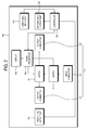
- FIG. 1 is a control block diagram illustrating a configuration of one of a plurality of display devices included in a video wall display system according to an exemplary embodiment.
- a display device 100 includes a plurality of pairs of input and output connectors 110, a signal processor 120, and a display 130.
- FIG. 1 shows only a pair of input and output connectors 110.
- Each display device according to an exemplary embodiment may include a plurality of pairs of input and output connectors 110, which will be described with reference to FIG. 2 .
- the pair of input and output connectors 110 include an input connector 111 connected to a first neighboring display device among the plurality of display devices to receive an image signal from the first neighboring display device and at least one output connector 112 and 113 connected to a second neighboring display device to output the image signal input to the input connector 111.
- the at least one output connector may include a first output connector 112 connected to the second neighboring display device and a second output connector 113 connected to a third neighboring display device in order to output the image signal.
- An image signal is input to the input connector 111 from the first neighboring display device of the plurality of display devices, and then transmitted to the signal processor 120 via a first switch 11 connected to the input connector 111.
- the signal processor 120 processes the image signal to be displayed on the display 130 and transmits the processed image signal to the display 130. Further, the signal processor 120 identifies whether the output connector 112 is actually connected to the second neighboring display device among at least one output connector connected to the second neighboring display device. Moreover, when the at least one output connector includes the first output connector 112 which outputs a signal to the second neighboring display device and the second output connector 113 which outputs a signal to the third neighboring display device, the signal processor 120 may identify which of the first output connector 112 and the second output connector 113 is actually connected to a neighboring display device.
- the signal processor 120 manipulates a second switch 12 so that the image signal is output to the second neighboring display device via the first output connector 112.
- the signal processor 120 manipulates the second switch 12 so that the image signal is output to the third neighboring display device via the second output connector 113.
- the signal processor 120 manipulates the second switch 12 so that the image signal is not output to any output connector 112 and 113.
- the signal processor 120 processes an image signal input to the input connector 111 and controls the pair of input and output connectors 110 so that the image signal is output or is not output to at least one output connector 112 and 113 connected to the second neighboring display device.
- one input connector 111 and at least one output connector 112 and 113 of the pair of input and output connectors 110 may be provided in different positions. That is, in the display device 100 with four sides (i.e., up, down, left, and right sides), if the input connector 111 is disposed on the down side, the output connector is disposed on at least one of the other three sides where the input connector 111 is not disposed.
- the two output connectors 112 and 113 may be disposed on two other sides of the three sides other than the down side.
- the two output connectors 112 and 113 may be disposed on the left and right sides, respectively, on the left and up sides, respectively, or on the up and right sides, respectively.
- the input and output connectors 110 may include a plurality of ports for high-definition multimedia interface (HDMI), a component connection, digital visual interface (DVI), RS232C communication, a broadcast signal receiver, an external device, etc.
- HDMI high-definition multimedia interface
- DVI digital visual interface
- RS232C communication a broadcast signal receiver, an external device, etc.
- the external device is a device which is capable of transmitting an image signal to the display device 100 and may include a personal computer (PC), a digital versatile disc (DVD) player, a Blu-ray disc (BD) player, a personal video recorder (PVR), an external server, a web server, a portable multimedia player, a mobile device, etc.
- PC personal computer
- DVD digital versatile disc
- BD Blu-ray disc
- PVR personal video recorder
- an external server a web server
- portable multimedia player a mobile device, etc.
- At least one of the display devices 100 may receive an image signal from an external device via the input connector 111. Then, the display device 100 transmits the image signal received from the external device to the signal processor 120, and the signal processor 120 outputs the image signal to at least one of the output connectors 112 and 113.
- the signal processor 120 processes the image signal input to the input connector 111 to be displayed on the display 130.
- the signal processor 120 may include a scaler (not shown), a decoder (not shown), etc.
- the signal processor 120 identifies which of the output connectors 112 and 113 is connected to a neighboring display device. Accordingly, the signal processor 120 controls the second switch 12 to determine which of the output connectors 112 and 113 an image signal is output to.
- the display 130 displays an image based on an image signal processed by the signal processor 120.
- the display 130 may include any type of displays to display an image, e.g., cathode ray tube (CRT), liquid crystal display (LCD), light emitting diode (LED) display, organic LED display (OLED), plasma display panel (PDP), etc.
- CTR cathode ray tube
- LCD liquid crystal display
- LED light emitting diode
- OLED organic LED display
- PDP plasma display panel
- each of the display devices may include one or more pairs of input and output connectors 110.
- FIG. 2 is a block diagram illustrating a configuration of one of a plurality of display devices included in a video wall display system according to another exemplary embodiment.
- a display device 100 may further include a user signal input unit 140, a controller 150, and a plurality of audio output units 161 and 162 in addition to at least one pair of input and output connectors 110, a signal processor 120, and a display 130, which are described above with reference to FIG. 1 .
- the pairs of input and output connectors 110, the signal processor 120, and the display 130 are explained above, descriptions thereof are omitted herein.
- the user signal input unit 140 is input with a signal corresponding to a user's input.
- the user signal input unit 140 is included in at least one of the plurality of display devices 100 of the video wall display system.
- a user signal input to the user signal input unit 140 may be input or output through the pairs of the input and output connectors 110.
- each of the display devices 100 may further include a serial communication interface for input and output of the user signal.
- the serial communication interface may be synchronous or asynchronous.
- the serial communication interface may be a universal asynchronous receiver and transmitter (UART).
- the pairs of input and output connectors 110 may include a port which enables serial communication, e.g., RS232C.
- a serial signal output through the serial communication interface may be transmitted to a neighboring display device via the port conducting serial communication.
- the controller 150 identifies a target display device of the plurality of display devices for the input user signal. As a result, if identified as a target display device of the input user signal, the controller 150 conducts a process corresponding to the user signal. If identified not as the target display device of the input user signal, the controller 150 controls the serial communication interface to convert the user signal into a signal for serial communication to be bypassed.
- the controller 150 carries out a process corresponding to the input user signal and controls the serial communication interface to convert the user signal into a signal for serial communication to be output.
- a signal input through the user signal input unit 140 may be a signal to set up an ID for each of the display devices 100.
- the controller 150 identifies whether a target display device of the user signal is a corresponding display device. Then, if identified as the target display device of the user signal, the controller 150 carries out ID setup of the corresponding display device. If identified not as the target display device of the user signal, the controller 150 converts the signal into a signal for serial communication to be bypassed.
- a signal input through the user signal input unit 140 may be a signal for at least one color adjustment to each of the display devices 100.
- the at least one color adjustment may include at least one of adjustment to screen brightness, tone of color, contrast, white balance, definition, and tint.
- the controller 150 identifies a target display device of the input user signal, and if identified as the target display device, the controller 150 conducts color adjustment corresponding to the user signal. If identified not as the target display device, the controller 150 bypasses the signal.
- the controller 150 carries out color adjustment to a corresponding display device 100 in accordance with a signal for overall color adjustment to the video wall display system.
- the audio output units 161 and 162 output a sound based on an audio signal having a plurality of sound sources transmitted through the pairs of input and output connectors 110.
- the controller 150 controls the audio output units 161 and 162 to output a sound on the basis of whether the audio signal is transmitted through the pairs of input and output connectors 110.
- FIG. 3 is a block diagram illustrating a configuration of a plurality of pairs of input and output connectors 110 of a display device 100 according to an exemplary embodiment. That is, FIG. 3 shows three pairs of input and output connectors 110 according to an exemplary embodiment.
- each pair of the three pairs of input and output connectors 110 includes one input connector 111 and two output connectors 112 and 113.
- the input connector 111 is connected to the two output connectors 112 and 113, and the two output connectors 112 and 113 are disposed in different adjacent directions from the input connector. Further, a plurality of input connectors 111 are provided, and disposed in different adjacent directions, respectively.
- an input connector A is connected to output connectors B and C.
- a signal input to input the connector A is output to one of the output connectors B and C.
- an input connector B is connected to output connectors A and C.
- a signal input to the input connector B is output to one of the output connectors A and C.
- an input connector C is connected to the output connectors A and B.
- a signal input to the input connector C is output to one of the output connectors A and B.
- the display device 100 includes a plurality of pairs of input and output connectors 110, and thus a plurality of display devices may be connected in serial in any direction, e.g., up, down, left and right. Accordingly, a configuration of cables may be simplified.
- FIG. 4 illustrates signal flow in a video wall display system having a plurality of display devices connected via a plurality of pairs of input and output connectors 110 according to an exemplary embodiment.
- a first display device receives an image signal from an external device
- the image signal is output through an output connector disposed on the right side of the first display device and input through an input connector disposed in the left side of a second display device.
- the image signal is output through an output connector disposed on the right side of the second display device and input to an input connector disposed on the left side of a third display device. Subsequently, the signal is output through an output connector disposed on the upper side of the third display device and input to an input connector disposed on the lower side of a fourth neighboring display device.
- the display devices are connected in serial through the plurality of the pairs of input and output connectors, so that the image signal input to the first display device may be transmitted to a ninth display device.
- an image signal input to the first display device may be transmitted to the ninth display device via a sixth display device, a seventh display device, an eighth display device, a fifth display device, the second display device, the third display device, and the fourth display device, in order.
- the video wall display system having a plurality of display devices may be formed in different types of video wall systems having various numbers of display devices, e.g., 2x2, 4x4 and 5x5, in addition to the 3x3 video wall.
- At least one of the display devices may further include a user signal input unit corresponding to a user's input, and a user signal input to the user signal input unit may be input and output through the pairs of input and output connectors.
- FIG. 5 is a related art video wall display system which is not capable of receiving a user's signal from an outside user signal input unit.
- a related art display device tends to be slimmer.
- a user signal input unit is often disposed not on the front side of the display device but on a lateral side.
- a display device with a user signal input unit disposed at a lateral side is positioned in a central position of a video wall display system, a display device which can not receive a user signal may occur, as pointed out in FIG. 5 .
- a user signal may be transmitted along the signal flow shown in FIG. 4 .
- At least one of the plurality of display devices further includes a user signal input unit 140, and a user signal received to the user signal input unit 140 is input and output via the pairs of input and output connectors 110 as well as the image signal explained in FIG. 4 . Accordingly, the user signal input to the input unit 140 is transmitted from a first display device to a ninth display device. In this regard, even if the display device in the central position of the video wall cannot directly receive a user signal, the display device can receive a user signal from a display device having the user signal input unit 140.
- the user signal may include an infrared (IR) signal, which is transmitted from the user signal input unit 140 such as an external remote controller.
- IR infrared
- Each of the display devices may further include a serial communication interface for input and output of the user signal.
- the serial communication interface may be synchronous or asynchronous.
- the serial communication interface may be a universal asynchronous receiver and transmitter (UART).
- the pairs of input and output connectors 110 may include a port (not shown) which enables serial communication, e.g., RS232C.
- a serial signal output through the serial communication interface may be transmitted to a neighboring display device via the port conducting serial communication.
- Each of the display devices 100 may further include a controller 150 which identifies a target display device of the input user signal.
- the controller 150 conducts a process corresponding to the user signal if identified as a target display device of the input user signal, and controls the serial communication interface to convert the user signal into a signal for serial communication to be bypassed if identified not as the target display device of the input user signal.
- the pairs of input and output connectors 110 connecting the display devices in serial enable position recognition even if individual IDs for the display devices are not set up.
- the controller 150 identifies a target display device of the user signal. Then, if identified as the target display device of the user signal, the controller 150 carries out a process of the user signal on a corresponding display device. If identified not as the target display device of the user signal, the controller 150 controls the serial communication interface to convert the user signal into a signal for serial communication to be bypassed to a neighboring display device.
- the controller 150 carries out a process corresponding to the input user signal and controls the serial communication interface to convert the user signal into a signal for serial communication to be output to a neighboring display device.
- the controller 150 of the first display device which receives a screen brightness control signal from a remote controller adjusts screen brightness in accordance with the signal and converts the control signal into a signal for serial communication to output to the second neighboring display device.
- the controller 150 of the second display device also adjusts screen brightness in accordance with the signal and outputs the control signal to the third neighboring display device.
- the control signal received by the first display device is transmitted to the ninth display device.
- a control signal for all the display devices of the system is received by a specific display device and transmitted to the rest of display devices.
- a control signal for a specific display device among the display devices is received by another display device and transmitted to the specific display device.
- ID setup and adjustment to screen brightness, tone of color, contrast, white balance, definition, and tint are enabled for the display devices in whole or individually.
- the controller 150 identifies whether a target display device of the user signal is a corresponding display device. Then, if identified as the target display device of the user signal, the controller 150 carries out ID setup of the corresponding display device. If identified not as the target display device of the user signal, the controller 150 converts the signal into a signal for serial communication to be bypassed.
- a signal input through the user signal input unit 140 is a signal for at least one color adjustment to each of the display devices selected from among, for example, adjustment to screen brightness, tone of color, contrast, white balance, definition, and tint
- the controller 150 identifies a target display device of the input user signal. Then, if identified as the target display device, the controller 150 conducts color adjustment corresponding to the user signal. If identified not as the target display device, the controller 150 bypasses the signal.
- the controller 150 carries out color adjustment to a corresponding display device in accordance with the signal for overall color adjustment to the video wall display system.
- the video wall display system has overall screen brightness adjustable from 0 to 100, and the overall screen brightness of the video wall display system is to be adjusted to 70 by the user signal.
- the controllers 150 of the respective display devices enable the display devices to have a screen brightness of 70, respectively, in accordance with the user signal for overall color adjustment.
- the controllers 150 of the display devices upwardly adjust the overall screen brightness of the display devices by 10 levels, respectively.
- the display system includes display devices A, B, C and D, and the display device A has a screen brightness of 40, the display device B has a screen brightness of 50, the display device C has a screen brightness of 60, and the display device D has a screen brightness of 65.
- the controller 150 of the display device A adjusts the screen brightness to 50
- the controller 150 of the display device B adjusts the screen brightness to 60
- the controller 150 of the display device C adjusts the screen brightness to 70
- the controller 150 of the display device D adjusts the screen brightness to 75.
- the controller 150 adjusts the at least one of tone of color, contrast, white balance, definition, and tint of a corresponding display device according to the signal.
- each of the display devices may include a plurality of audio output units 161 and 162 outputting a sound based on an audio signal having a plurality of sound sources transmitted through the pairs of input and output connectors 110 and a controller 150 controlling the audio output units 161 and 162 to output a sound based on whether the audio signal is transmitted.
- Each of the display devices in the video wall display system may include a plurality of audio output units 161 and 162 disposed on the right and left sides of the display device.
- an audio signal is also transmitted through the plurality of a pair of input and output connectors 110 along with an image signal.
- FIG. 6 illustrates an audio signal output from a plurality of audio output units 161 and 162 in a video wall display system according to an exemplary embodiment.
- each display device includes a plurality of audio output units 161 and 162 disposed on the right and left sides.
- a sound with desired quality may not be expressed due to collision/interference in sound.
- the display devices in the video wall display system include a controller 150 controlling the audio output units 161 and 162 which output a sound on the basis of whether the audio signals are transmitted via a plurality of pairs of input and output connectors 110 connecting the display devices.
- each of the display devices according 100 may include a first audio output unit 161 and a second audio output unit 162.
- the audio output units 161 and 162 are not limited to this number, but a number of audio output units 161 and 162 corresponding to a plurality of sound sources may be provided.
- an audio signal is not transmitted in the upward and downward directions in the second, fifth, and eighth display devices.
- the controllers 150 of the second, fifth, and eighth display devices may control all the audio output units 161 and 162 of the second, fifth, and eighty display devices not to output a sound, respectively.
- the controller 150 also controls the audio output units 161 and 162 outputting a sound on the basis of a transmission direction of the audio signal via the pairs of input and output connectors.
- the controller 150 controls the audio output units 161 and 162 not to output a sound.
- an audio signal is transmitted only in the left and right directions through the pairs of input and output connectors 110 in the second, fifth, and eighth display devices.
- the controllers 150 of the second, fifth, and eighth display devices may control all the audio output units 161 and 162 of the second, fifth, and eighty display devices not to output a sound, respectively.
- the controller 150 controls the audio output units 161 and 162 so that only audio output units 162 disposed in the right side of the display devices output a sound.
- an audio signal is input in the left direction through the pairs of input and output connectors 110 but is not output in the right direction in the third display device, an audio signal is input in the downward direction through the pairs of input and output connectors 110 but is not output in the right direction in the fourth display device, or an audio signal is input in the left direction through the pairs of input and output connectors 110 but is not output in any direction in the ninth display device.
- the controller 150 controls audio output units 162 disposed on the right side of the display devices not to output a sound.
- the controller 150 controls the audio output units 161 and 162 so that only audio output units 161 disposed in the left side of the display devices output a sound.
- an audio signal is input in the downward direction through the pairs of input and output connectors 110 but is not output in the left direction in the first display device, an audio signal is input in the right direction through the pairs of input and output connectors 110 but is not output in the left direction in the sixth display device, or an audio signal is input in the downward direction through the pairs of input and output connectors 110 but is not output in the left direction in the seventh display device.
- the controller 150 controls audio output units 161 disposed on the left side of the display devices not to output a sound.
- the exemplary embodiments can also be embodied as computer-readable code on a computer-readable recording medium.
- the computer-readable recording medium is any data storage device that can store data that can be thereafter read by a computer system. Examples of the computer-readable recording medium include read-only memory (ROM), random-access memory (RAM), CD-ROMs, magnetic tapes, floppy disks, and optical data storage devices.
- the computer-readable recording medium can also be distributed over network-coupled computer systems so that the computer-readable code is stored and executed in a distributed fashion.
- the exemplary embodiments may be written as computer programs transmitted over a computer-readable transmission medium, such as a carrier wave, and received and implemented in general-use digital computers that execute the programs.
- one or more units of the display device 100 can include a processor or microprocessor executing a computer program stored in a computer-readable medium, such as a local storage.
Landscapes
- Engineering & Computer Science (AREA)
- Theoretical Computer Science (AREA)
- Physics & Mathematics (AREA)
- General Physics & Mathematics (AREA)
- Computer Hardware Design (AREA)
- Multimedia (AREA)
- Human Computer Interaction (AREA)
- General Engineering & Computer Science (AREA)
- Controls And Circuits For Display Device (AREA)
Priority Applications (1)
| Application Number | Priority Date | Filing Date | Title |
|---|---|---|---|
| EP20170058.0A EP3702903A1 (fr) | 2009-11-25 | 2010-09-01 | Système d'affichage vidéo sur un mur |
Applications Claiming Priority (1)
| Application Number | Priority Date | Filing Date | Title |
|---|---|---|---|
| KR1020090114705A KR101632572B1 (ko) | 2009-11-25 | 2009-11-25 | 비디오 월 디스플레이시스템 |
Related Child Applications (2)
| Application Number | Title | Priority Date | Filing Date |
|---|---|---|---|
| EP20170058.0A Division-Into EP3702903A1 (fr) | 2009-11-25 | 2010-09-01 | Système d'affichage vidéo sur un mur |
| EP20170058.0A Division EP3702903A1 (fr) | 2009-11-25 | 2010-09-01 | Système d'affichage vidéo sur un mur |
Publications (3)
| Publication Number | Publication Date |
|---|---|
| EP2328073A2 true EP2328073A2 (fr) | 2011-06-01 |
| EP2328073A3 EP2328073A3 (fr) | 2011-09-14 |
| EP2328073B1 EP2328073B1 (fr) | 2020-05-27 |
Family
ID=43607663
Family Applications (2)
| Application Number | Title | Priority Date | Filing Date |
|---|---|---|---|
| EP10174911.7A Active EP2328073B1 (fr) | 2009-11-25 | 2010-09-01 | Système d'affichage vidéo sur un mur |
| EP20170058.0A Pending EP3702903A1 (fr) | 2009-11-25 | 2010-09-01 | Système d'affichage vidéo sur un mur |
Family Applications After (1)
| Application Number | Title | Priority Date | Filing Date |
|---|---|---|---|
| EP20170058.0A Pending EP3702903A1 (fr) | 2009-11-25 | 2010-09-01 | Système d'affichage vidéo sur un mur |
Country Status (3)
| Country | Link |
|---|---|
| US (1) | US9134950B2 (fr) |
| EP (2) | EP2328073B1 (fr) |
| KR (1) | KR101632572B1 (fr) |
Cited By (12)
| Publication number | Priority date | Publication date | Assignee | Title |
|---|---|---|---|---|
| CN103035222A (zh) * | 2011-10-10 | 2013-04-10 | 台达电子工业股份有限公司 | 用以调整电视墙的声控系统 |
| EP2660710A1 (fr) * | 2012-05-04 | 2013-11-06 | Samsung Electronics Co., Ltd. | Procédé de détection automatique d'un agencement de mur vidéo et système de mur vidéo l'utilisant |
| EP2725482A1 (fr) * | 2012-10-29 | 2014-04-30 | Samsung Electronics Co., Ltd | Appareil de traitement d'images et son procédé de commande |
| CN104243870A (zh) * | 2013-06-17 | 2014-12-24 | 三星电子株式会社 | 显示系统及其控制方法 |
| KR20150068104A (ko) * | 2013-12-11 | 2015-06-19 | 삼성전자주식회사 | 디스플레이 장치 및 그 제어방법 |
| WO2017054886A1 (fr) | 2015-10-02 | 2017-04-06 | Arcelik Anonim Sirketi | Système et procédé de fonctionnement d'un dispositif d'affichage vidéo-mosaïque par une station de commande |
| WO2017059905A1 (fr) | 2015-10-08 | 2017-04-13 | Arcelik Anonim Sirketi | Système et procédé pour la réorganisation dynamique d'un système d'affichage de type mosaïque vidéo |
| WO2017059906A1 (fr) | 2015-10-08 | 2017-04-13 | Arcelik Anonim Sirketi | Système et procédé de définition d'emplacement d'un dispositif d'affichage d'image dans un système d'affichage à mur vidéo |
| WO2018206329A1 (fr) | 2017-05-09 | 2018-11-15 | Arcelik Anonim Sirketi | Procédé de transfert de données de système de mur vidéo |
| WO2018206088A1 (fr) | 2017-05-09 | 2018-11-15 | Arcelik Anonim Sirketi | Système et procédé d'ajustement des réglages d'un système d'affichage de mur vidéo |
| EP3506076A1 (fr) * | 2017-12-28 | 2019-07-03 | Vestel Elektronik Sanayi ve Ticaret A.S. | Positionnement de mur vidéo actif |
| US12431108B1 (en) | 2024-03-26 | 2025-09-30 | Toshiba Global Commerce Solutions, Inc. | Display mapping methodology |
Families Citing this family (40)
| Publication number | Priority date | Publication date | Assignee | Title |
|---|---|---|---|---|
| CN102682739B (zh) * | 2011-03-07 | 2015-02-25 | 台达电子工业股份有限公司 | 电视墙系统及其控制方法 |
| KR101920264B1 (ko) * | 2012-08-02 | 2019-02-08 | 삼성전자주식회사 | 디스플레이장치 및 그 제어방법과, 디스플레이 시스템 |
| US9400627B2 (en) * | 2012-12-07 | 2016-07-26 | Samsung Electronics Co., Ltd. | Display including signal transmission scheme using optical interconnection and electrical interconnection |
| TWI573109B (zh) * | 2012-12-19 | 2017-03-01 | 鴻海精密工業股份有限公司 | 電視牆及其黑框消除結構 |
| TWI566215B (zh) * | 2012-12-24 | 2017-01-11 | 鴻海精密工業股份有限公司 | 電視牆及其黑框消除透鏡 |
| CN103903519A (zh) * | 2012-12-25 | 2014-07-02 | 鸿富锦精密工业(深圳)有限公司 | 电视墙及其黑框消除结构 |
| US10055866B2 (en) * | 2013-02-21 | 2018-08-21 | Dolby Laboratories Licensing Corporation | Systems and methods for appearance mapping for compositing overlay graphics |
| TWI536362B (zh) | 2014-03-21 | 2016-06-01 | 佳世達科技股份有限公司 | 定位顯示畫面系統 |
| CN103945254B (zh) * | 2014-03-26 | 2017-09-26 | 苏州佳世达电通有限公司 | 显示装置及定位该显示装置的显示画面的方法 |
| US10235120B2 (en) | 2014-08-04 | 2019-03-19 | Samsung Electronics Co., Ltd. | Display apparatus, display system, and controlling method thereof |
| CN104333713B (zh) * | 2014-10-24 | 2017-12-19 | 苏州佳世达电通有限公司 | 显示装置的设定方法 |
| KR102253315B1 (ko) * | 2014-12-04 | 2021-05-17 | 엘지전자 주식회사 | 비디오월 시스템 |
| CN106292845B (zh) * | 2015-05-19 | 2019-04-23 | 鸿富锦精密工业(武汉)有限公司 | 组合式电子设备 |
| KR102362054B1 (ko) * | 2015-10-22 | 2022-02-11 | 삼성전자주식회사 | 다중 디스플레이 시스템을 구성하는 디스플레이 장치 및 그 제어 방법 |
| KR102508148B1 (ko) * | 2016-01-07 | 2023-03-09 | 엘지전자 주식회사 | 디지털 디바이스 및 그를 이용한 컬러 제어 시스템 및 방법 |
| US10838613B2 (en) | 2016-02-17 | 2020-11-17 | Trufan Llc | Consumer electronic entertainment and display system |
| US20170238041A1 (en) * | 2016-02-17 | 2017-08-17 | Christopher Alsante | Consumer electronic entertainment and display system |
| KR20180020830A (ko) * | 2016-08-19 | 2018-02-28 | 삼성전자주식회사 | 비디오월 시스템 및 그 제어방법과, 디스플레이장치 |
| TR201614110A1 (tr) * | 2016-10-07 | 2018-04-24 | Arcelik As | Vi̇deo duvari görüntüleme si̇stemleri̇nde teki̇l görüntüleme ci̇hazlarinin kontrol edi̇lmesi̇ni̇ sağlayan bi̇r si̇stem ve yöntem |
| CN109804644B (zh) * | 2016-10-13 | 2021-06-01 | 连株式会社 | 声音输出方法、计算机装置及计算机可读记录介质 |
| WO2018101514A1 (fr) * | 2016-12-01 | 2018-06-07 | 엘지전자 주식회사 | Dispositif d'affichage d'image et système d'affichage d'image le comprenant |
| US10303259B2 (en) * | 2017-04-03 | 2019-05-28 | Youspace, Inc. | Systems and methods for gesture-based interaction |
| US10437342B2 (en) | 2016-12-05 | 2019-10-08 | Youspace, Inc. | Calibration systems and methods for depth-based interfaces with disparate fields of view |
| US10303417B2 (en) | 2017-04-03 | 2019-05-28 | Youspace, Inc. | Interactive systems for depth-based input |
| US11202028B2 (en) | 2017-04-05 | 2021-12-14 | Samsung Electronics Co., Ltd. | Display device configuring multi display system and control method thereof |
| KR102496339B1 (ko) * | 2017-10-31 | 2023-02-06 | 삼성전자주식회사 | 디스플레이 장치 및 디스플레이 시스템 |
| KR102407475B1 (ko) | 2017-12-08 | 2022-06-13 | 삼성전자주식회사 | 디스플레이 장치 및 그 제어 방법 |
| KR102662666B1 (ko) | 2018-11-09 | 2024-05-03 | 삼성전자주식회사 | 디스플레이 장치, 디스플레이 장치 제어방법 및 디스플레이 시스템 |
| CN209895328U (zh) * | 2019-08-06 | 2020-01-03 | 京东方科技集团股份有限公司 | 一种交互式显示设备及交互式显示系统 |
| CN212364987U (zh) | 2019-08-06 | 2021-01-15 | 京东方科技集团股份有限公司 | 一种框架及多屏互动显示设备 |
| DE112020005127T5 (de) * | 2019-10-25 | 2022-12-01 | H2Vr Holdco, Inc. | Unbegrenzter pixelcanvas für led-videowände |
| US11474571B2 (en) * | 2020-05-19 | 2022-10-18 | Samsung Electronics Co., Ltd. | Display panel module and electronic device including multiple display panel modules |
| KR20220094263A (ko) | 2020-12-28 | 2022-07-06 | 삼성디스플레이 주식회사 | 타일형 표시 장치 및 영상 보정 방법 |
| KR20230008954A (ko) * | 2021-07-07 | 2023-01-17 | 삼성디스플레이 주식회사 | 표시 장치 및 복수의 표시 장치들의 제어 방법 |
| CN117597662A (zh) | 2021-11-02 | 2024-02-23 | 三星电子株式会社 | 显示设备及其控制方法 |
| KR20230063716A (ko) * | 2021-11-02 | 2023-05-09 | 삼성전자주식회사 | 디스플레이 모듈 및 그 제어 방법 |
| KR20230090909A (ko) | 2021-12-15 | 2023-06-22 | 삼성전자주식회사 | 디스플레이 장치 및 그 제어 방법 |
| CN114512093A (zh) * | 2022-02-25 | 2022-05-17 | 杭州海康威视数字技术股份有限公司 | Led驱动电路及led显示装置 |
| CN120476440A (zh) * | 2022-11-09 | 2025-08-12 | 三星电子株式会社 | 包括多个驱动器ic的显示设备、模块化显示设备及其控制方法 |
| US11907462B1 (en) | 2023-02-10 | 2024-02-20 | Toshiba Global Commerce Solutions, Inc. | Screen mapping and spatial arrangement system |
Family Cites Families (15)
| Publication number | Priority date | Publication date | Assignee | Title |
|---|---|---|---|---|
| KR950004458B1 (ko) | 1992-06-26 | 1995-05-01 | 주식회사금성사 | 무선 멀티비젼 조정회로 |
| JPH10333631A (ja) * | 1997-06-02 | 1998-12-18 | Daichiyuu Denshi:Kk | 拡張型表示装置および拡張型表示装置を用いた表示システム |
| JPH1175145A (ja) | 1997-08-29 | 1999-03-16 | Mitsubishi Electric Corp | ビデオプロジェクター制御装置 |
| JPH11252483A (ja) | 1998-02-26 | 1999-09-17 | Toshiba Corp | マルチ画面表示装置 |
| JP3417326B2 (ja) * | 1999-01-29 | 2003-06-16 | 日亜化学工業株式会社 | Led表示装置及びそれを用いたled表示装置の制御方法 |
| TW582015B (en) | 2000-06-30 | 2004-04-01 | Nichia Corp | Display unit communication system, communication method, display unit, communication circuit and terminal adapter |
| EP1548573A1 (fr) | 2003-12-23 | 2005-06-29 | Barco N.V. | Système de contrôle hiérarchique pour un affichage émissif à écran large en mosaique |
| EP1550947A3 (fr) | 2003-12-23 | 2009-06-17 | Barco N.V. | Affichage émissif en mosaique configurable |
| US7450085B2 (en) * | 2004-10-07 | 2008-11-11 | Barco, Naamloze Vennootschap | Intelligent lighting module and method of operation of such an intelligent lighting module |
| GB2424510A (en) * | 2005-03-24 | 2006-09-27 | Nesta | Interactive blocks. |
| KR100759139B1 (ko) * | 2005-09-09 | 2007-09-14 | 엘지전자 주식회사 | 멀티비젼 시스템의 제어장치 및 그 방법 |
| JP4973919B2 (ja) * | 2006-10-23 | 2012-07-11 | ソニー株式会社 | 出力制御システムおよび方法、出力制御装置および方法、並びにプログラム |
| KR20080082301A (ko) * | 2007-03-08 | 2008-09-11 | 삼성전자주식회사 | Usb 커넥터를 이용하여 데이터를 전송하는 외부기기를제어하는 영상 디스플레이 장치 및 그 방법 |
| KR101414898B1 (ko) | 2007-10-02 | 2014-07-03 | 엘지전자 주식회사 | 디스플레이 기기를 이용한 멀티비전의 구성 및 제어 방법 |
| US9128661B2 (en) * | 2008-07-02 | 2015-09-08 | Med Et Al, Inc. | Communication blocks having multiple-planes of detection components and associated method of conveying information based on their arrangement |
-
2009
- 2009-11-25 KR KR1020090114705A patent/KR101632572B1/ko not_active Expired - Fee Related
-
2010
- 2010-07-22 US US12/841,816 patent/US9134950B2/en active Active
- 2010-09-01 EP EP10174911.7A patent/EP2328073B1/fr active Active
- 2010-09-01 EP EP20170058.0A patent/EP3702903A1/fr active Pending
Non-Patent Citations (1)
| Title |
|---|
| None |
Cited By (14)
| Publication number | Priority date | Publication date | Assignee | Title |
|---|---|---|---|---|
| CN103035222A (zh) * | 2011-10-10 | 2013-04-10 | 台达电子工业股份有限公司 | 用以调整电视墙的声控系统 |
| US9354840B2 (en) | 2012-05-04 | 2016-05-31 | Samsung Electronics Co., Ltd. | Automatic detection method of video wall arrangement and video wall system using the same |
| EP2660710A1 (fr) * | 2012-05-04 | 2013-11-06 | Samsung Electronics Co., Ltd. | Procédé de détection automatique d'un agencement de mur vidéo et système de mur vidéo l'utilisant |
| KR20130124101A (ko) * | 2012-05-04 | 2013-11-13 | 삼성전자주식회사 | 비디오 월 배열 자동 검출방법 및 비디오 월 시스템 |
| EP2725482A1 (fr) * | 2012-10-29 | 2014-04-30 | Samsung Electronics Co., Ltd | Appareil de traitement d'images et son procédé de commande |
| CN104243870A (zh) * | 2013-06-17 | 2014-12-24 | 三星电子株式会社 | 显示系统及其控制方法 |
| KR20150068104A (ko) * | 2013-12-11 | 2015-06-19 | 삼성전자주식회사 | 디스플레이 장치 및 그 제어방법 |
| WO2017054886A1 (fr) | 2015-10-02 | 2017-04-06 | Arcelik Anonim Sirketi | Système et procédé de fonctionnement d'un dispositif d'affichage vidéo-mosaïque par une station de commande |
| WO2017059905A1 (fr) | 2015-10-08 | 2017-04-13 | Arcelik Anonim Sirketi | Système et procédé pour la réorganisation dynamique d'un système d'affichage de type mosaïque vidéo |
| WO2017059906A1 (fr) | 2015-10-08 | 2017-04-13 | Arcelik Anonim Sirketi | Système et procédé de définition d'emplacement d'un dispositif d'affichage d'image dans un système d'affichage à mur vidéo |
| WO2018206329A1 (fr) | 2017-05-09 | 2018-11-15 | Arcelik Anonim Sirketi | Procédé de transfert de données de système de mur vidéo |
| WO2018206088A1 (fr) | 2017-05-09 | 2018-11-15 | Arcelik Anonim Sirketi | Système et procédé d'ajustement des réglages d'un système d'affichage de mur vidéo |
| EP3506076A1 (fr) * | 2017-12-28 | 2019-07-03 | Vestel Elektronik Sanayi ve Ticaret A.S. | Positionnement de mur vidéo actif |
| US12431108B1 (en) | 2024-03-26 | 2025-09-30 | Toshiba Global Commerce Solutions, Inc. | Display mapping methodology |
Also Published As
| Publication number | Publication date |
|---|---|
| KR101632572B1 (ko) | 2016-07-01 |
| KR20110058049A (ko) | 2011-06-01 |
| EP2328073B1 (fr) | 2020-05-27 |
| US9134950B2 (en) | 2015-09-15 |
| US20110122048A1 (en) | 2011-05-26 |
| EP3702903A1 (fr) | 2020-09-02 |
| EP2328073A3 (fr) | 2011-09-14 |
Similar Documents
| Publication | Publication Date | Title |
|---|---|---|
| US9134950B2 (en) | Video wall display system | |
| CN100558163C (zh) | 多屏幕系统及其驱动方法 | |
| US8350898B2 (en) | Head-mounted visual display device with stereo vision and its system | |
| US10509614B2 (en) | Video display apparatus-apparatus communication | |
| EP2026574A2 (fr) | Appareil d'affichage et son procédé de commande | |
| US9973725B2 (en) | Modular television system | |
| US20060203004A1 (en) | Display apparatus | |
| US20170098295A1 (en) | Display control apparatus | |
| EP2814242A1 (fr) | Dispositif de communication, système de communication, procédé d'utilisation de dispositif de communication et programme | |
| US20110072380A1 (en) | Display apparatus, display apparatus system and resolution control method thereof | |
| EP3703354A1 (fr) | Dispositif d'affichage et procédé de commande correspondant | |
| US9967540B2 (en) | Ultra high definition 3D conversion device and an ultra high definition 3D display system | |
| US20100118000A1 (en) | Display apparatus and control method thereof | |
| US20150278143A1 (en) | Method And Device For Connecting USB Port And Method For Transmitting Data | |
| WO2014007458A1 (fr) | Dispositif d'affichage et son procédé de commande | |
| IL265789B2 (en) | Secure video streaming device | |
| EP4517731A1 (fr) | Dispositif d'affichage d'image | |
| KR20120064212A (ko) | 멀티비젼 표시장치 및 그의 표시방법 | |
| US20090080538A1 (en) | Method and Apparatus for Decoding a Video Signal | |
| KR102615070B1 (ko) | 디스플레이 장치, 및 그 제어방법 | |
| US10547810B2 (en) | Display apparatus and control method thereof | |
| KR20120061619A (ko) | 디스플레이장치 및 그의 식별자 설정 방법 | |
| JP2008219544A (ja) | 表示装置 | |
| KR101310936B1 (ko) | 표시 장치 및 이의 구동 방법 | |
| KR100751130B1 (ko) | 영상기기의 통합 잭 시스템 |
Legal Events
| Date | Code | Title | Description |
|---|---|---|---|
| PUAI | Public reference made under article 153(3) epc to a published international application that has entered the european phase |
Free format text: ORIGINAL CODE: 0009012 |
|
| AK | Designated contracting states |
Kind code of ref document: A2 Designated state(s): AL AT BE BG CH CY CZ DE DK EE ES FI FR GB GR HR HU IE IS IT LI LT LU LV MC MK MT NL NO PL PT RO SE SI SK SM TR |
|
| AX | Request for extension of the european patent |
Extension state: BA ME RS |
|
| PUAL | Search report despatched |
Free format text: ORIGINAL CODE: 0009013 |
|
| AK | Designated contracting states |
Kind code of ref document: A3 Designated state(s): AL AT BE BG CH CY CZ DE DK EE ES FI FR GB GR HR HU IE IS IT LI LT LU LV MC MK MT NL NO PL PT RO SE SI SK SM TR |
|
| AX | Request for extension of the european patent |
Extension state: BA ME RS |
|
| RIC1 | Information provided on ipc code assigned before grant |
Ipc: G09G 5/00 20060101ALI20110811BHEP Ipc: G06F 3/14 20060101AFI20110811BHEP |
|
| 17P | Request for examination filed |
Effective date: 20120309 |
|
| RAP1 | Party data changed (applicant data changed or rights of an application transferred) |
Owner name: SAMSUNG ELECTRONICS CO., LTD. |
|
| STAA | Information on the status of an ep patent application or granted ep patent |
Free format text: STATUS: EXAMINATION IS IN PROGRESS |
|
| 17Q | First examination report despatched |
Effective date: 20161103 |
|
| GRAP | Despatch of communication of intention to grant a patent |
Free format text: ORIGINAL CODE: EPIDOSNIGR1 |
|
| STAA | Information on the status of an ep patent application or granted ep patent |
Free format text: STATUS: GRANT OF PATENT IS INTENDED |
|
| INTG | Intention to grant announced |
Effective date: 20191210 |
|
| GRAS | Grant fee paid |
Free format text: ORIGINAL CODE: EPIDOSNIGR3 |
|
| GRAA | (expected) grant |
Free format text: ORIGINAL CODE: 0009210 |
|
| STAA | Information on the status of an ep patent application or granted ep patent |
Free format text: STATUS: THE PATENT HAS BEEN GRANTED |
|
| AK | Designated contracting states |
Kind code of ref document: B1 Designated state(s): AL AT BE BG CH CY CZ DE DK EE ES FI FR GB GR HR HU IE IS IT LI LT LU LV MC MK MT NL NO PL PT RO SE SI SK SM TR |
|
| RAP1 | Party data changed (applicant data changed or rights of an application transferred) |
Owner name: SAMSUNG ELECTRONICS CO., LTD. |
|
| REG | Reference to a national code |
Ref country code: GB Ref legal event code: FG4D |
|
| REG | Reference to a national code |
Ref country code: CH Ref legal event code: EP |
|
| REG | Reference to a national code |
Ref country code: DE Ref legal event code: R096 Ref document number: 602010064442 Country of ref document: DE |
|
| REG | Reference to a national code |
Ref country code: AT Ref legal event code: REF Ref document number: 1275245 Country of ref document: AT Kind code of ref document: T Effective date: 20200615 |
|
| REG | Reference to a national code |
Ref country code: LT Ref legal event code: MG4D |
|
| PG25 | Lapsed in a contracting state [announced via postgrant information from national office to epo] |
Ref country code: LT Free format text: LAPSE BECAUSE OF FAILURE TO SUBMIT A TRANSLATION OF THE DESCRIPTION OR TO PAY THE FEE WITHIN THE PRESCRIBED TIME-LIMIT Effective date: 20200527 Ref country code: SE Free format text: LAPSE BECAUSE OF FAILURE TO SUBMIT A TRANSLATION OF THE DESCRIPTION OR TO PAY THE FEE WITHIN THE PRESCRIBED TIME-LIMIT Effective date: 20200527 Ref country code: IS Free format text: LAPSE BECAUSE OF FAILURE TO SUBMIT A TRANSLATION OF THE DESCRIPTION OR TO PAY THE FEE WITHIN THE PRESCRIBED TIME-LIMIT Effective date: 20200927 Ref country code: NO Free format text: LAPSE BECAUSE OF FAILURE TO SUBMIT A TRANSLATION OF THE DESCRIPTION OR TO PAY THE FEE WITHIN THE PRESCRIBED TIME-LIMIT Effective date: 20200827 Ref country code: FI Free format text: LAPSE BECAUSE OF FAILURE TO SUBMIT A TRANSLATION OF THE DESCRIPTION OR TO PAY THE FEE WITHIN THE PRESCRIBED TIME-LIMIT Effective date: 20200527 Ref country code: GR Free format text: LAPSE BECAUSE OF FAILURE TO SUBMIT A TRANSLATION OF THE DESCRIPTION OR TO PAY THE FEE WITHIN THE PRESCRIBED TIME-LIMIT Effective date: 20200828 Ref country code: PT Free format text: LAPSE BECAUSE OF FAILURE TO SUBMIT A TRANSLATION OF THE DESCRIPTION OR TO PAY THE FEE WITHIN THE PRESCRIBED TIME-LIMIT Effective date: 20200928 |
|
| REG | Reference to a national code |
Ref country code: NL Ref legal event code: MP Effective date: 20200527 |
|
| PG25 | Lapsed in a contracting state [announced via postgrant information from national office to epo] |
Ref country code: HR Free format text: LAPSE BECAUSE OF FAILURE TO SUBMIT A TRANSLATION OF THE DESCRIPTION OR TO PAY THE FEE WITHIN THE PRESCRIBED TIME-LIMIT Effective date: 20200527 Ref country code: LV Free format text: LAPSE BECAUSE OF FAILURE TO SUBMIT A TRANSLATION OF THE DESCRIPTION OR TO PAY THE FEE WITHIN THE PRESCRIBED TIME-LIMIT Effective date: 20200527 Ref country code: BG Free format text: LAPSE BECAUSE OF FAILURE TO SUBMIT A TRANSLATION OF THE DESCRIPTION OR TO PAY THE FEE WITHIN THE PRESCRIBED TIME-LIMIT Effective date: 20200827 |
|
| REG | Reference to a national code |
Ref country code: AT Ref legal event code: MK05 Ref document number: 1275245 Country of ref document: AT Kind code of ref document: T Effective date: 20200527 |
|
| PG25 | Lapsed in a contracting state [announced via postgrant information from national office to epo] |
Ref country code: NL Free format text: LAPSE BECAUSE OF FAILURE TO SUBMIT A TRANSLATION OF THE DESCRIPTION OR TO PAY THE FEE WITHIN THE PRESCRIBED TIME-LIMIT Effective date: 20200527 Ref country code: AL Free format text: LAPSE BECAUSE OF FAILURE TO SUBMIT A TRANSLATION OF THE DESCRIPTION OR TO PAY THE FEE WITHIN THE PRESCRIBED TIME-LIMIT Effective date: 20200527 |
|
| PG25 | Lapsed in a contracting state [announced via postgrant information from national office to epo] |
Ref country code: CZ Free format text: LAPSE BECAUSE OF FAILURE TO SUBMIT A TRANSLATION OF THE DESCRIPTION OR TO PAY THE FEE WITHIN THE PRESCRIBED TIME-LIMIT Effective date: 20200527 Ref country code: RO Free format text: LAPSE BECAUSE OF FAILURE TO SUBMIT A TRANSLATION OF THE DESCRIPTION OR TO PAY THE FEE WITHIN THE PRESCRIBED TIME-LIMIT Effective date: 20200527 Ref country code: ES Free format text: LAPSE BECAUSE OF FAILURE TO SUBMIT A TRANSLATION OF THE DESCRIPTION OR TO PAY THE FEE WITHIN THE PRESCRIBED TIME-LIMIT Effective date: 20200527 Ref country code: IT Free format text: LAPSE BECAUSE OF FAILURE TO SUBMIT A TRANSLATION OF THE DESCRIPTION OR TO PAY THE FEE WITHIN THE PRESCRIBED TIME-LIMIT Effective date: 20200527 Ref country code: SM Free format text: LAPSE BECAUSE OF FAILURE TO SUBMIT A TRANSLATION OF THE DESCRIPTION OR TO PAY THE FEE WITHIN THE PRESCRIBED TIME-LIMIT Effective date: 20200527 Ref country code: EE Free format text: LAPSE BECAUSE OF FAILURE TO SUBMIT A TRANSLATION OF THE DESCRIPTION OR TO PAY THE FEE WITHIN THE PRESCRIBED TIME-LIMIT Effective date: 20200527 Ref country code: AT Free format text: LAPSE BECAUSE OF FAILURE TO SUBMIT A TRANSLATION OF THE DESCRIPTION OR TO PAY THE FEE WITHIN THE PRESCRIBED TIME-LIMIT Effective date: 20200527 Ref country code: DK Free format text: LAPSE BECAUSE OF FAILURE TO SUBMIT A TRANSLATION OF THE DESCRIPTION OR TO PAY THE FEE WITHIN THE PRESCRIBED TIME-LIMIT Effective date: 20200527 |
|
| PG25 | Lapsed in a contracting state [announced via postgrant information from national office to epo] |
Ref country code: SK Free format text: LAPSE BECAUSE OF FAILURE TO SUBMIT A TRANSLATION OF THE DESCRIPTION OR TO PAY THE FEE WITHIN THE PRESCRIBED TIME-LIMIT Effective date: 20200527 Ref country code: PL Free format text: LAPSE BECAUSE OF FAILURE TO SUBMIT A TRANSLATION OF THE DESCRIPTION OR TO PAY THE FEE WITHIN THE PRESCRIBED TIME-LIMIT Effective date: 20200527 |
|
| REG | Reference to a national code |
Ref country code: DE Ref legal event code: R097 Ref document number: 602010064442 Country of ref document: DE |
|
| PLBE | No opposition filed within time limit |
Free format text: ORIGINAL CODE: 0009261 |
|
| STAA | Information on the status of an ep patent application or granted ep patent |
Free format text: STATUS: NO OPPOSITION FILED WITHIN TIME LIMIT |
|
| PG25 | Lapsed in a contracting state [announced via postgrant information from national office to epo] |
Ref country code: MC Free format text: LAPSE BECAUSE OF FAILURE TO SUBMIT A TRANSLATION OF THE DESCRIPTION OR TO PAY THE FEE WITHIN THE PRESCRIBED TIME-LIMIT Effective date: 20200527 |
|
| REG | Reference to a national code |
Ref country code: CH Ref legal event code: PL |
|
| 26N | No opposition filed |
Effective date: 20210302 |
|
| PG25 | Lapsed in a contracting state [announced via postgrant information from national office to epo] |
Ref country code: SI Free format text: LAPSE BECAUSE OF FAILURE TO SUBMIT A TRANSLATION OF THE DESCRIPTION OR TO PAY THE FEE WITHIN THE PRESCRIBED TIME-LIMIT Effective date: 20200527 |
|
| REG | Reference to a national code |
Ref country code: BE Ref legal event code: MM Effective date: 20200930 |
|
| PG25 | Lapsed in a contracting state [announced via postgrant information from national office to epo] |
Ref country code: LU Free format text: LAPSE BECAUSE OF NON-PAYMENT OF DUE FEES Effective date: 20200901 |
|
| PG25 | Lapsed in a contracting state [announced via postgrant information from national office to epo] |
Ref country code: FR Free format text: LAPSE BECAUSE OF NON-PAYMENT OF DUE FEES Effective date: 20200930 |
|
| PG25 | Lapsed in a contracting state [announced via postgrant information from national office to epo] |
Ref country code: BE Free format text: LAPSE BECAUSE OF NON-PAYMENT OF DUE FEES Effective date: 20200930 Ref country code: CH Free format text: LAPSE BECAUSE OF NON-PAYMENT OF DUE FEES Effective date: 20200930 Ref country code: LI Free format text: LAPSE BECAUSE OF NON-PAYMENT OF DUE FEES Effective date: 20200930 Ref country code: IE Free format text: LAPSE BECAUSE OF NON-PAYMENT OF DUE FEES Effective date: 20200901 |
|
| PGFP | Annual fee paid to national office [announced via postgrant information from national office to epo] |
Ref country code: GB Payment date: 20210824 Year of fee payment: 12 |
|
| PG25 | Lapsed in a contracting state [announced via postgrant information from national office to epo] |
Ref country code: TR Free format text: LAPSE BECAUSE OF FAILURE TO SUBMIT A TRANSLATION OF THE DESCRIPTION OR TO PAY THE FEE WITHIN THE PRESCRIBED TIME-LIMIT Effective date: 20200527 Ref country code: MT Free format text: LAPSE BECAUSE OF FAILURE TO SUBMIT A TRANSLATION OF THE DESCRIPTION OR TO PAY THE FEE WITHIN THE PRESCRIBED TIME-LIMIT Effective date: 20200527 Ref country code: CY Free format text: LAPSE BECAUSE OF FAILURE TO SUBMIT A TRANSLATION OF THE DESCRIPTION OR TO PAY THE FEE WITHIN THE PRESCRIBED TIME-LIMIT Effective date: 20200527 |
|
| PG25 | Lapsed in a contracting state [announced via postgrant information from national office to epo] |
Ref country code: MK Free format text: LAPSE BECAUSE OF FAILURE TO SUBMIT A TRANSLATION OF THE DESCRIPTION OR TO PAY THE FEE WITHIN THE PRESCRIBED TIME-LIMIT Effective date: 20200527 |
|
| GBPC | Gb: european patent ceased through non-payment of renewal fee |
Effective date: 20220901 |
|
| PG25 | Lapsed in a contracting state [announced via postgrant information from national office to epo] |
Ref country code: GB Free format text: LAPSE BECAUSE OF NON-PAYMENT OF DUE FEES Effective date: 20220901 |
|
| PGFP | Annual fee paid to national office [announced via postgrant information from national office to epo] |
Ref country code: DE Payment date: 20250820 Year of fee payment: 16 |