EP2328132A2 - Fernsteuerungsvorrichtung - Google Patents
Fernsteuerungsvorrichtung Download PDFInfo
- Publication number
- EP2328132A2 EP2328132A2 EP10189364A EP10189364A EP2328132A2 EP 2328132 A2 EP2328132 A2 EP 2328132A2 EP 10189364 A EP10189364 A EP 10189364A EP 10189364 A EP10189364 A EP 10189364A EP 2328132 A2 EP2328132 A2 EP 2328132A2
- Authority
- EP
- European Patent Office
- Prior art keywords
- cover
- generator
- energy
- closed position
- open position
- Prior art date
- Legal status (The legal status is an assumption and is not a legal conclusion. Google has not performed a legal analysis and makes no representation as to the accuracy of the status listed.)
- Granted
Links
- 230000005674 electromagnetic induction Effects 0.000 claims description 6
- 230000007246 mechanism Effects 0.000 claims description 3
- 230000007704 transition Effects 0.000 claims description 3
- 230000005291 magnetic effect Effects 0.000 description 18
- 230000005284 excitation Effects 0.000 description 5
- 230000004913 activation Effects 0.000 description 4
- 230000004907 flux Effects 0.000 description 4
- 230000009471 action Effects 0.000 description 2
- 239000003302 ferromagnetic material Substances 0.000 description 2
- 206010001488 Aggression Diseases 0.000 description 1
- 230000016571 aggressive behavior Effects 0.000 description 1
- 230000005540 biological transmission Effects 0.000 description 1
- 239000003990 capacitor Substances 0.000 description 1
- 238000004146 energy storage Methods 0.000 description 1
- 230000005294 ferromagnetic effect Effects 0.000 description 1
- 230000006698 induction Effects 0.000 description 1
- 239000000696 magnetic material Substances 0.000 description 1
- 239000000463 material Substances 0.000 description 1
- 230000035699 permeability Effects 0.000 description 1
- 230000000717 retained effect Effects 0.000 description 1
- 238000004804 winding Methods 0.000 description 1
Images


Classifications
-
- G—PHYSICS
- G08—SIGNALLING
- G08C—TRANSMISSION SYSTEMS FOR MEASURED VALUES, CONTROL OR SIMILAR SIGNALS
- G08C17/00—Arrangements for transmitting signals characterised by the use of a wireless electrical link
- G08C17/02—Arrangements for transmitting signals characterised by the use of a wireless electrical link using a radio link
-
- G—PHYSICS
- G08—SIGNALLING
- G08C—TRANSMISSION SYSTEMS FOR MEASURED VALUES, CONTROL OR SIMILAR SIGNALS
- G08C23/00—Non-electrical signal transmission systems, e.g. optical systems
- G08C23/04—Non-electrical signal transmission systems, e.g. optical systems using light waves, e.g. infrared
-
- H—ELECTRICITY
- H02—GENERATION; CONVERSION OR DISTRIBUTION OF ELECTRIC POWER
- H02K—DYNAMO-ELECTRIC MACHINES
- H02K35/00—Generators with reciprocating, oscillating or vibrating coil system, magnet, armature or other part of the magnetic circuit
- H02K35/02—Generators with reciprocating, oscillating or vibrating coil system, magnet, armature or other part of the magnetic circuit with moving magnets and stationary coil systems
-
- G—PHYSICS
- G08—SIGNALLING
- G08C—TRANSMISSION SYSTEMS FOR MEASURED VALUES, CONTROL OR SIMILAR SIGNALS
- G08C2201/00—Transmission systems of control signals via wireless link
- G08C2201/10—Power supply of remote control devices
- G08C2201/11—Energy harvesting
- G08C2201/112—Mechanical energy, e.g. vibration, piezoelectric
-
- H—ELECTRICITY
- H01—ELECTRIC ELEMENTS
- H01H—ELECTRIC SWITCHES; RELAYS; SELECTORS; EMERGENCY PROTECTIVE DEVICES
- H01H2239/00—Miscellaneous
- H01H2239/076—Key stroke generating power
-
- H—ELECTRICITY
- H02—GENERATION; CONVERSION OR DISTRIBUTION OF ELECTRIC POWER
- H02K—DYNAMO-ELECTRIC MACHINES
- H02K7/00—Arrangements for handling mechanical energy structurally associated with dynamo-electric machines, e.g. structural association with mechanical driving motors or auxiliary dynamo-electric machines
- H02K7/18—Structural association of electric generators with mechanical driving motors, e.g. with turbines
- H02K7/1869—Linear generators; sectional generators
- H02K7/1876—Linear generators; sectional generators with reciprocating, linearly oscillating or vibrating parts
Definitions
- the present invention relates to a remote control device comprising in particular an energy generator for converting mechanical energy into electrical energy.
- remote control devices employing an energy generator to convert mechanical energy into electrical energy.
- This is for example wireless switches in which pressing the button causes the actuation of the generator and the generation of an electric current.
- the generated electric current is used by a transmitter to send a message to a remote receiver associated with a device to be controlled such as for example a lamp.
- the generator may for example be of the electromagnetic induction type or of the piezoelectric type.
- the effort required to send the message must often be substantial because the button cooperates directly with the energy generator.
- these devices are not adapted to be used in the form of a portable remote control because they are too bulky and not sufficiently protected to resist all the aggressions of their environment.
- the object of the invention is to propose a new remote control device that makes it possible in particular to overcome the disadvantages of the prior art presented above.
- the device comprises means for storing the electrical energy generated by the generator during the transition from the closed position to the open position of the cover and during the transition from the open position to the position of closing the hood.
- the device comprises mechanical drive means arranged between the cover and the generator and having a cam and cam follower mechanism.
- the cover is movable in a sliding movement relative to a base of the housing.
- the operation interface comprises one or more buttons.
- the generator is electromagnetic induction.
- the transmitter is radiofrequency.
- the transmitter is of the infrared type.
- the receiver is associated with a device to be controlled.
- the device to be controlled is a lamp.
- the invention consists of a remote control device which comprises in particular a generator for converting a mechanical energy into electrical energy.
- the principle of the invention consists in particular in separating the energy generation function from the activation function of sending the message. More specifically, the mechanical movement for operating the generator to generate the electrical energy is different from the activation movement of the transmitter to send the message.
- the user of the control device of the invention must therefore perform at least two distinct movements to validate the sending of a message to the receiver.
- the remote control device of the invention comprises a housing 6, for example made of plastic, having a base 60 and a movable cover 61 able to move on the base 60 between a closed position ( figure 1 ) and an open position ( figure 2 ).
- the cover 61 may for example perform a sliding movement, a rotational movement or any other type of movement relative to the base 60 between its two positions.
- the control device In the closed position of the cover 61, the control device has for example a parallelepipedal general shape.
- the movable cover 61 is for example mounted on two longitudinal parallel rails made on the base 60.
- the device further comprises an actuation interface mounted on the surface of the base 60 of the housing 6 situated opposite the cover 61.
- This actuation interface makes it possible to activate the transmitter 8 for the transmission of A message to the receiver 9.
- the sliding cover 61 is intended to mask or unmask this operating interface according to whether it is respectively in the closed position or in the open position.
- the actuation interface comprises for example a mechanical position sensor.
- the actuation interface may for example be in the form of one or more buttons (7, figure 2 ). Each button 7 will be for example a key type electronic such as that found on a mobile phone.
- the device further comprises an energy generator 1 housed inside the base 60 and intended to convert mechanical energy into electrical energy.
- This generator 1 is for example electromagnetic induction type or piezoelectric type.
- the mechanical energy used to drive the generator 1 is provided by the sliding movement of the cover 61 on the base 60 from its closed position to its open position or its open position to its closed position.
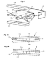
- An electromagnetic induction energy generator 1 is shown in FIG. figures 3 and 4 . It makes it possible to generate an electric current in an excitation coil 2 by varying the magnetic flux passing through the coil 2 by an external mechanical action.
- the generator 1 comprises in particular a magnetic circuit formed of a fixed part and a movable part 5, through which a magnetic field can flow, and an excitation coil 2.
- the magnetic flux in the magnetic circuit is defined by the instantaneous angular position of the moving part 5 with respect to the fixed part so that the movement of the movable part 5 with respect to the fixed part creates a variation of the magnetic flux through the coil 2 which causes the creation of an electric current in the coil 2.
- the voltage created across the coil 2 by the variation of the magnetic flux depends on the time and therefore the speed of movement of the movable part 5 with respect to the fixed part.
- the excitation coil 2 comprises a frame 20 made of a non-magnetic material, on which is wound a winding 21 of N turns of a conductive wire ( figures 3 and 4 ).
- the armature 20 has a central opening formed along a longitudinal axis (A) and whose dimensions are adapted to be traversed several times by the magnetic circuit.
- the fixed part of the magnetic circuit passes through the central opening of the coil 2 twice, forming a loop.
- the magnetic circuit thus crosses the central opening of the coil 2 a first time, then bypasses the coil 2 to form the loop, and passes through the central opening of the coil 2 a second time.
- the moving part 5 of the magnetic circuit has for example a symmetrical H-shaped shape comprising for example a permanent magnet 50 taken between two parallel layers 51a, 51b of ferromagnetic material, an upper layer 51a and a lower layer 51b.
- This moving part 5 is rotatably mounted on a horizontal axis of rotation (R) perpendicular to the longitudinal axis (A) of the central opening of the armature 20.
- the axis of rotation (R) is materialized on the figure 3 by a cylindrical piece 52 secured to a support piece 53 (not shown on the figure 4 mounted on the movable part 5 and integral in rotation with the movable part 5.
- the fixed part of the magnetic circuit is made of a material of high magnetic permeability such as a ferromagnetic material.
- the fixed part comprises a U-shaped base 30 spanning the excitation coil 2.
- the fixed part of the magnetic circuit also comprises a first arm 31 and a second arm 32 distinct, non-contiguous and non-identical, one of the arms being the reflection of the other in a mirror.
- the first arm 31 is connected to the first end of the base 30 while the second arm 32 is connected to the second end of the base 30.
- These two arms 31, 32 are L-shaped and distinctly pass through the opening central of the armature 20 in two planes parallel to the longitudinal axis (A) of the central opening of the coil 2.
- each of the arms 31, 32 are positioned on either side of the magnet permanent 50 of the movable portion 5 and between the two ferromagnetic layers 51 a, 51 b of the movable portion 5.
- Each arm 31, 32 forms a stop for the movable portion 5 and defines two opposite bearing surfaces, a range of upper support and a lower support pad.
- the moving part 5 has a degree of freedom in rotation between the abutments formed by each of the arms 31, 32.
- the magnetic field flowing in the arms 31, 32 always passes through the central opening of the coil 2 in the same direction.
- the magnetic field passes through the central opening of the excitation coil 2 twice in the same direction.
- the movable portion 5 carries a rocking movement about its axis (R) and can take two distinct end positions defined by the stops, in each of which the movable portion 5 is retained by magnetic forces.
- R axis
- the movable portion 5 is detached from one of its extreme positions, beyond a central equilibrium position, it is instantly attracted by magnetic effect to the other extreme position. This phenomenon is described in particular in the application for GB Patent 1,312,927 .
- the energy generator is housed in the base 60 of the housing and is mechanically coupled to the hood via mechanical drive means for converting the movement of the cover 61 between its two positions in a movement of the moving part 5 of the generator 1.
- these mechanical drive means may for example comprise a cam and cam follower mechanism arranged between the cover 61 and the moving part 5 of the generator 1.
- the cam comprises for example a ramp 62 made on a part integral with the cover 61 and cooperating with a pin arranged at a first end of a lever 63 and forming the cam follower.
- the second end of the lever 63 cooperates with the mobile part 5 of the energy generator 1 housed in the housing.
- the cover 61 drives the lever in a pivoting movement, the latter then driving the mobile part of the generator 1 in rotation about its axis.
- the control device of the invention also comprises an emitter 8, for example of radiofrequency type, powered by the current produced by the generator 1 for sending radio signals to a remote receiver 9 and electronic circuits 4 comprising, in particular, storage means for the radio frequency. electrical energy generated by the generator 1, such as capacitors, to smooth the amount of current to be delivered downstream to the transmitter ( figure 2 ).
- the receiver 9 is associated with a device to be controlled such as for example a lamp 91.
- the control device comprises an antenna 80 that can be integrated in the housing 6 and for sending the message to the receiver 9 which includes a corresponding antenna 90 to receive the message.
- the wireless communication protocol used between the transmitter 8 and the receiver 9 will for example be ZIGBEE.
- the transmitter may be of the infrared type.
- the energy generator, the transmitter 8 and the electronic circuits 4 are placed on an activation circuit controlled by the operating interface.
- the transmitter 8 can thus be supplied with current by the energy generator 1 and is able to be actuated by means of the actuation interface to validate the sending of a message.
- the message may comprise several identical successive frames.
- a user opens the cover 61 of the device which generates an electrical energy.
- This electrical energy is stored in the energy storage means waiting to be used by the transmitter 8 for sending a message.
- the user can act on the operation interface for example by pressing one or more buttons 7.
- An action on a button 7 and closes the electrical activation circuit of the transmitter.
- the electrical energy stored in the storage means is then injected into the transmitter 8 which sends a message to the receiver 9 by radio frequency. If after sending a message, all the energy generated and stored has not been consumed, a new button press can be performed.
- the user has finished, he closes the cover 61 on the base 60 to generate a new amount of energy that is stored in the storage means.
Landscapes
- Physics & Mathematics (AREA)
- General Physics & Mathematics (AREA)
- Engineering & Computer Science (AREA)
- Computer Networks & Wireless Communication (AREA)
- Power Engineering (AREA)
- Selective Calling Equipment (AREA)
- Connection Of Motors, Electrical Generators, Mechanical Devices, And The Like (AREA)
Applications Claiming Priority (1)
| Application Number | Priority Date | Filing Date | Title |
|---|---|---|---|
| FR0958367A FR2953059B1 (fr) | 2009-11-25 | 2009-11-25 | Dispositif de commande a distance |
Publications (3)
| Publication Number | Publication Date |
|---|---|
| EP2328132A2 true EP2328132A2 (de) | 2011-06-01 |
| EP2328132A3 EP2328132A3 (de) | 2017-11-01 |
| EP2328132B1 EP2328132B1 (de) | 2018-07-04 |
Family
ID=42229574
Family Applications (1)
| Application Number | Title | Priority Date | Filing Date |
|---|---|---|---|
| EP10189364.2A Active EP2328132B1 (de) | 2009-11-25 | 2010-10-29 | Fernsteuerungsvorrichtung |
Country Status (2)
| Country | Link |
|---|---|
| EP (1) | EP2328132B1 (de) |
| FR (1) | FR2953059B1 (de) |
Cited By (3)
| Publication number | Priority date | Publication date | Assignee | Title |
|---|---|---|---|---|
| CN105161340A (zh) * | 2015-07-31 | 2015-12-16 | 武汉领普科技有限公司 | 电源自给式多按键开关装置 |
| WO2018006223A1 (zh) * | 2016-07-04 | 2018-01-11 | 王楚 | 智能台灯 |
| FR3079654A1 (fr) * | 2018-04-03 | 2019-10-04 | Schneider Electric Industries Sas | Dispositif de commande sans fil et ensemble comprenant un tel dispositif, ainsi qu'un autre dispositif de commande apte a etre branche sur un fil electrique |
Citations (1)
| Publication number | Priority date | Publication date | Assignee | Title |
|---|---|---|---|---|
| GB1312927A (en) | 1970-05-22 | 1973-04-11 | Zentronik Veb K | Non-contacting switching device for producing electrical pulses |
Family Cites Families (4)
| Publication number | Priority date | Publication date | Assignee | Title |
|---|---|---|---|---|
| WO2006009540A1 (en) * | 2004-06-19 | 2006-01-26 | Face Bradbury R | Self-powered switch initiation system |
| FR2893780A1 (fr) * | 2005-11-22 | 2007-05-25 | Schneider Electric Ind Sas | Dispositif autonome de generation d'energie electrique |
| FR2910677B1 (fr) * | 2006-12-26 | 2009-02-27 | Somfy Sas | Capteur-emetteur de securite pour la detection de vent dans une installation domotique |
| WO2009020757A1 (en) * | 2007-08-05 | 2009-02-12 | Masco Corporation | Door notification system |
-
2009
- 2009-11-25 FR FR0958367A patent/FR2953059B1/fr not_active Expired - Fee Related
-
2010
- 2010-10-29 EP EP10189364.2A patent/EP2328132B1/de active Active
Patent Citations (1)
| Publication number | Priority date | Publication date | Assignee | Title |
|---|---|---|---|---|
| GB1312927A (en) | 1970-05-22 | 1973-04-11 | Zentronik Veb K | Non-contacting switching device for producing electrical pulses |
Cited By (4)
| Publication number | Priority date | Publication date | Assignee | Title |
|---|---|---|---|---|
| CN105161340A (zh) * | 2015-07-31 | 2015-12-16 | 武汉领普科技有限公司 | 电源自给式多按键开关装置 |
| WO2018006223A1 (zh) * | 2016-07-04 | 2018-01-11 | 王楚 | 智能台灯 |
| FR3079654A1 (fr) * | 2018-04-03 | 2019-10-04 | Schneider Electric Industries Sas | Dispositif de commande sans fil et ensemble comprenant un tel dispositif, ainsi qu'un autre dispositif de commande apte a etre branche sur un fil electrique |
| EP3550537A1 (de) * | 2018-04-03 | 2019-10-09 | Schneider Electric Industries SAS | Drahtlose steuervorrichtung und anordnung, die eine solche vorrichtung sowie eine andere steuervorrichtung umfasst, die an eine elektrische leitung angeschlossen werden kann |
Also Published As
| Publication number | Publication date |
|---|---|
| EP2328132A3 (de) | 2017-11-01 |
| EP2328132B1 (de) | 2018-07-04 |
| FR2953059B1 (fr) | 2011-11-04 |
| FR2953059A1 (fr) | 2011-05-27 |
Similar Documents
| Publication | Publication Date | Title |
|---|---|---|
| CA2767166C (fr) | Dispositif de commutation sans-fil | |
| CA2630554C (fr) | Dispositif autonome de generation d'energie electrique | |
| EP2250725B1 (de) | Stromerzeugungsvorrichtung mit zwei mobilen teilen | |
| EP2609607B1 (de) | Vorrichtung zur detektion und zur signalisierung einer statusänderung eines druckknopfs | |
| EP3488517B1 (de) | Elektromagnetischer energiewandler | |
| EP2072959B1 (de) | Apparat mit kontaktlosen Regelungsmitteln | |
| FR2953659A1 (fr) | Dispositif generateur d'energie electrique et telecommande pourvue d'un tel dispositif | |
| EP2328132B1 (de) | Fernsteuerungsvorrichtung | |
| EP2395625B1 (de) | Fernsteuerungsvorrichtung, die eine Energieakkumulationsvorrichtung einschließt | |
| WO2011069879A1 (fr) | Dispositif generateur d'energie electrique | |
| WO2020109744A2 (fr) | Dispositif d'effort reglable | |
| EP2085987B1 (de) | Steuerungsvorrichtung mit zwei verschiedenen Betätigungsarten | |
| EP3550537B1 (de) | Drahtlose steuervorrichtung und anordnung, die eine solche vorrichtung sowie eine andere steuervorrichtung umfasst, die an eine elektrische leitung angeschlossen werden kann | |
| EP2311056B1 (de) | Fernsteuerungsvorrichtung für einen schalter mit einem verstärkungsmechanismus und einem drehgenerator und mit einer derartigen vorrichtung ausgestatteter schalter | |
| FR2520156A1 (fr) | Interrupteur electrique actionne par flotteur | |
| FR2486304A1 (fr) | Interrupteur magneto-thermique differentiel | |
| FR2988218A1 (fr) | Bloc declencheur pour appareil de protection electrique et appareil de protection electrique comportant un tel bloc | |
| FR2737820A1 (fr) | Moteur electrique synchrone, plus particulierement destine a des dispositifs programmateurs d'appareils electromenagers | |
| FR3066640A1 (fr) | Demarreur de moteur thermique muni d'un contacteur electromagnetique a trois bornes realisant une fonction de limiteur de courant |
Legal Events
| Date | Code | Title | Description |
|---|---|---|---|
| PUAI | Public reference made under article 153(3) epc to a published international application that has entered the european phase |
Free format text: ORIGINAL CODE: 0009012 |
|
| AK | Designated contracting states |
Kind code of ref document: A2 Designated state(s): AL AT BE BG CH CY CZ DE DK EE ES FI FR GB GR HR HU IE IS IT LI LT LU LV MC MK MT NL NO PL PT RO RS SE SI SK SM TR |
|
| AX | Request for extension of the european patent |
Extension state: BA ME |
|
| PUAL | Search report despatched |
Free format text: ORIGINAL CODE: 0009013 |
|
| AK | Designated contracting states |
Kind code of ref document: A3 Designated state(s): AL AT BE BG CH CY CZ DE DK EE ES FI FR GB GR HR HU IE IS IT LI LT LU LV MC MK MT NL NO PL PT RO RS SE SI SK SM TR |
|
| AX | Request for extension of the european patent |
Extension state: BA ME |
|
| RIC1 | Information provided on ipc code assigned before grant |
Ipc: G08C 23/04 20060101ALI20170925BHEP Ipc: H02K 7/18 20060101ALI20170925BHEP Ipc: H02K 35/02 20060101ALI20170925BHEP Ipc: G08C 17/02 20060101AFI20170925BHEP |
|
| 17P | Request for examination filed |
Effective date: 20171108 |
|
| RBV | Designated contracting states (corrected) |
Designated state(s): AL AT BE BG CH CY CZ DE DK EE ES FI FR GB GR HR HU IE IS IT LI LT LU LV MC MK MT NL NO PL PT RO RS SE SI SK SM TR |
|
| GRAP | Despatch of communication of intention to grant a patent |
Free format text: ORIGINAL CODE: EPIDOSNIGR1 |
|
| INTG | Intention to grant announced |
Effective date: 20180405 |
|
| RIN1 | Information on inventor provided before grant (corrected) |
Inventor name: ATTIER, PIERRE |
|
| GRAS | Grant fee paid |
Free format text: ORIGINAL CODE: EPIDOSNIGR3 |
|
| GRAA | (expected) grant |
Free format text: ORIGINAL CODE: 0009210 |
|
| AK | Designated contracting states |
Kind code of ref document: B1 Designated state(s): AL AT BE BG CH CY CZ DE DK EE ES FI FR GB GR HR HU IE IS IT LI LT LU LV MC MK MT NL NO PL PT RO RS SE SI SK SM TR |
|
| REG | Reference to a national code |
Ref country code: GB Ref legal event code: FG4D Free format text: NOT ENGLISH |
|
| REG | Reference to a national code |
Ref country code: CH Ref legal event code: EP |
|
| REG | Reference to a national code |
Ref country code: AT Ref legal event code: REF Ref document number: 1015331 Country of ref document: AT Kind code of ref document: T Effective date: 20180715 |
|
| REG | Reference to a national code |
Ref country code: IE Ref legal event code: FG4D Free format text: LANGUAGE OF EP DOCUMENT: FRENCH |
|
| REG | Reference to a national code |
Ref country code: DE Ref legal event code: R096 Ref document number: 602010051615 Country of ref document: DE |
|
| REG | Reference to a national code |
Ref country code: FR Ref legal event code: PLFP Year of fee payment: 9 |
|
| REG | Reference to a national code |
Ref country code: NL Ref legal event code: MP Effective date: 20180704 |
|
| REG | Reference to a national code |
Ref country code: LT Ref legal event code: MG4D |
|
| REG | Reference to a national code |
Ref country code: AT Ref legal event code: MK05 Ref document number: 1015331 Country of ref document: AT Kind code of ref document: T Effective date: 20180704 |
|
| PG25 | Lapsed in a contracting state [announced via postgrant information from national office to epo] |
Ref country code: NL Free format text: LAPSE BECAUSE OF FAILURE TO SUBMIT A TRANSLATION OF THE DESCRIPTION OR TO PAY THE FEE WITHIN THE PRESCRIBED TIME-LIMIT Effective date: 20180704 |
|
| PG25 | Lapsed in a contracting state [announced via postgrant information from national office to epo] |
Ref country code: GR Free format text: LAPSE BECAUSE OF FAILURE TO SUBMIT A TRANSLATION OF THE DESCRIPTION OR TO PAY THE FEE WITHIN THE PRESCRIBED TIME-LIMIT Effective date: 20181005 Ref country code: FI Free format text: LAPSE BECAUSE OF FAILURE TO SUBMIT A TRANSLATION OF THE DESCRIPTION OR TO PAY THE FEE WITHIN THE PRESCRIBED TIME-LIMIT Effective date: 20180704 Ref country code: SE Free format text: LAPSE BECAUSE OF FAILURE TO SUBMIT A TRANSLATION OF THE DESCRIPTION OR TO PAY THE FEE WITHIN THE PRESCRIBED TIME-LIMIT Effective date: 20180704 Ref country code: LT Free format text: LAPSE BECAUSE OF FAILURE TO SUBMIT A TRANSLATION OF THE DESCRIPTION OR TO PAY THE FEE WITHIN THE PRESCRIBED TIME-LIMIT Effective date: 20180704 Ref country code: PL Free format text: LAPSE BECAUSE OF FAILURE TO SUBMIT A TRANSLATION OF THE DESCRIPTION OR TO PAY THE FEE WITHIN THE PRESCRIBED TIME-LIMIT Effective date: 20180704 Ref country code: IS Free format text: LAPSE BECAUSE OF FAILURE TO SUBMIT A TRANSLATION OF THE DESCRIPTION OR TO PAY THE FEE WITHIN THE PRESCRIBED TIME-LIMIT Effective date: 20181104 Ref country code: AT Free format text: LAPSE BECAUSE OF FAILURE TO SUBMIT A TRANSLATION OF THE DESCRIPTION OR TO PAY THE FEE WITHIN THE PRESCRIBED TIME-LIMIT Effective date: 20180704 Ref country code: RS Free format text: LAPSE BECAUSE OF FAILURE TO SUBMIT A TRANSLATION OF THE DESCRIPTION OR TO PAY THE FEE WITHIN THE PRESCRIBED TIME-LIMIT Effective date: 20180704 Ref country code: NO Free format text: LAPSE BECAUSE OF FAILURE TO SUBMIT A TRANSLATION OF THE DESCRIPTION OR TO PAY THE FEE WITHIN THE PRESCRIBED TIME-LIMIT Effective date: 20181004 Ref country code: CZ Free format text: LAPSE BECAUSE OF FAILURE TO SUBMIT A TRANSLATION OF THE DESCRIPTION OR TO PAY THE FEE WITHIN THE PRESCRIBED TIME-LIMIT Effective date: 20180704 Ref country code: BG Free format text: LAPSE BECAUSE OF FAILURE TO SUBMIT A TRANSLATION OF THE DESCRIPTION OR TO PAY THE FEE WITHIN THE PRESCRIBED TIME-LIMIT Effective date: 20181004 |
|
| PG25 | Lapsed in a contracting state [announced via postgrant information from national office to epo] |
Ref country code: AL Free format text: LAPSE BECAUSE OF FAILURE TO SUBMIT A TRANSLATION OF THE DESCRIPTION OR TO PAY THE FEE WITHIN THE PRESCRIBED TIME-LIMIT Effective date: 20180704 Ref country code: ES Free format text: LAPSE BECAUSE OF FAILURE TO SUBMIT A TRANSLATION OF THE DESCRIPTION OR TO PAY THE FEE WITHIN THE PRESCRIBED TIME-LIMIT Effective date: 20180704 Ref country code: HR Free format text: LAPSE BECAUSE OF FAILURE TO SUBMIT A TRANSLATION OF THE DESCRIPTION OR TO PAY THE FEE WITHIN THE PRESCRIBED TIME-LIMIT Effective date: 20180704 Ref country code: LV Free format text: LAPSE BECAUSE OF FAILURE TO SUBMIT A TRANSLATION OF THE DESCRIPTION OR TO PAY THE FEE WITHIN THE PRESCRIBED TIME-LIMIT Effective date: 20180704 |
|
| REG | Reference to a national code |
Ref country code: DE Ref legal event code: R097 Ref document number: 602010051615 Country of ref document: DE |
|
| PG25 | Lapsed in a contracting state [announced via postgrant information from national office to epo] |
Ref country code: EE Free format text: LAPSE BECAUSE OF FAILURE TO SUBMIT A TRANSLATION OF THE DESCRIPTION OR TO PAY THE FEE WITHIN THE PRESCRIBED TIME-LIMIT Effective date: 20180704 Ref country code: RO Free format text: LAPSE BECAUSE OF FAILURE TO SUBMIT A TRANSLATION OF THE DESCRIPTION OR TO PAY THE FEE WITHIN THE PRESCRIBED TIME-LIMIT Effective date: 20180704 Ref country code: IT Free format text: LAPSE BECAUSE OF FAILURE TO SUBMIT A TRANSLATION OF THE DESCRIPTION OR TO PAY THE FEE WITHIN THE PRESCRIBED TIME-LIMIT Effective date: 20180704 |
|
| PLBE | No opposition filed within time limit |
Free format text: ORIGINAL CODE: 0009261 |
|
| STAA | Information on the status of an ep patent application or granted ep patent |
Free format text: STATUS: NO OPPOSITION FILED WITHIN TIME LIMIT |
|
| PG25 | Lapsed in a contracting state [announced via postgrant information from national office to epo] |
Ref country code: SM Free format text: LAPSE BECAUSE OF FAILURE TO SUBMIT A TRANSLATION OF THE DESCRIPTION OR TO PAY THE FEE WITHIN THE PRESCRIBED TIME-LIMIT Effective date: 20180704 Ref country code: DK Free format text: LAPSE BECAUSE OF FAILURE TO SUBMIT A TRANSLATION OF THE DESCRIPTION OR TO PAY THE FEE WITHIN THE PRESCRIBED TIME-LIMIT Effective date: 20180704 Ref country code: SK Free format text: LAPSE BECAUSE OF FAILURE TO SUBMIT A TRANSLATION OF THE DESCRIPTION OR TO PAY THE FEE WITHIN THE PRESCRIBED TIME-LIMIT Effective date: 20180704 |
|
| REG | Reference to a national code |
Ref country code: CH Ref legal event code: PL |
|
| 26N | No opposition filed |
Effective date: 20190405 |
|
| REG | Reference to a national code |
Ref country code: BE Ref legal event code: MM Effective date: 20181031 |
|
| PG25 | Lapsed in a contracting state [announced via postgrant information from national office to epo] |
Ref country code: LU Free format text: LAPSE BECAUSE OF NON-PAYMENT OF DUE FEES Effective date: 20181029 Ref country code: MC Free format text: LAPSE BECAUSE OF FAILURE TO SUBMIT A TRANSLATION OF THE DESCRIPTION OR TO PAY THE FEE WITHIN THE PRESCRIBED TIME-LIMIT Effective date: 20180704 |
|
| REG | Reference to a national code |
Ref country code: IE Ref legal event code: MM4A |
|
| PG25 | Lapsed in a contracting state [announced via postgrant information from national office to epo] |
Ref country code: SI Free format text: LAPSE BECAUSE OF FAILURE TO SUBMIT A TRANSLATION OF THE DESCRIPTION OR TO PAY THE FEE WITHIN THE PRESCRIBED TIME-LIMIT Effective date: 20180704 Ref country code: LI Free format text: LAPSE BECAUSE OF NON-PAYMENT OF DUE FEES Effective date: 20181031 Ref country code: CH Free format text: LAPSE BECAUSE OF NON-PAYMENT OF DUE FEES Effective date: 20181031 Ref country code: BE Free format text: LAPSE BECAUSE OF NON-PAYMENT OF DUE FEES Effective date: 20181031 |
|
| PG25 | Lapsed in a contracting state [announced via postgrant information from national office to epo] |
Ref country code: IE Free format text: LAPSE BECAUSE OF NON-PAYMENT OF DUE FEES Effective date: 20181029 |
|
| PG25 | Lapsed in a contracting state [announced via postgrant information from national office to epo] |
Ref country code: MT Free format text: LAPSE BECAUSE OF FAILURE TO SUBMIT A TRANSLATION OF THE DESCRIPTION OR TO PAY THE FEE WITHIN THE PRESCRIBED TIME-LIMIT Effective date: 20180704 |
|
| PG25 | Lapsed in a contracting state [announced via postgrant information from national office to epo] |
Ref country code: TR Free format text: LAPSE BECAUSE OF FAILURE TO SUBMIT A TRANSLATION OF THE DESCRIPTION OR TO PAY THE FEE WITHIN THE PRESCRIBED TIME-LIMIT Effective date: 20180704 |
|
| PG25 | Lapsed in a contracting state [announced via postgrant information from national office to epo] |
Ref country code: PT Free format text: LAPSE BECAUSE OF FAILURE TO SUBMIT A TRANSLATION OF THE DESCRIPTION OR TO PAY THE FEE WITHIN THE PRESCRIBED TIME-LIMIT Effective date: 20180704 |
|
| PG25 | Lapsed in a contracting state [announced via postgrant information from national office to epo] |
Ref country code: CY Free format text: LAPSE BECAUSE OF FAILURE TO SUBMIT A TRANSLATION OF THE DESCRIPTION OR TO PAY THE FEE WITHIN THE PRESCRIBED TIME-LIMIT Effective date: 20180704 Ref country code: HU Free format text: LAPSE BECAUSE OF FAILURE TO SUBMIT A TRANSLATION OF THE DESCRIPTION OR TO PAY THE FEE WITHIN THE PRESCRIBED TIME-LIMIT; INVALID AB INITIO Effective date: 20101029 Ref country code: MK Free format text: LAPSE BECAUSE OF NON-PAYMENT OF DUE FEES Effective date: 20180704 |
|
| PGFP | Annual fee paid to national office [announced via postgrant information from national office to epo] |
Ref country code: DE Payment date: 20241029 Year of fee payment: 15 |
|
| PGFP | Annual fee paid to national office [announced via postgrant information from national office to epo] |
Ref country code: GB Payment date: 20241023 Year of fee payment: 15 |
|
| PGFP | Annual fee paid to national office [announced via postgrant information from national office to epo] |
Ref country code: FR Payment date: 20241025 Year of fee payment: 15 |