EP2328261A2 - Actionneur électrique - Google Patents
Actionneur électrique Download PDFInfo
- Publication number
- EP2328261A2 EP2328261A2 EP10014735A EP10014735A EP2328261A2 EP 2328261 A2 EP2328261 A2 EP 2328261A2 EP 10014735 A EP10014735 A EP 10014735A EP 10014735 A EP10014735 A EP 10014735A EP 2328261 A2 EP2328261 A2 EP 2328261A2
- Authority
- EP
- European Patent Office
- Prior art keywords
- rotor
- actuator
- electric machine
- electric
- rotating
- Prior art date
- Legal status (The legal status is an assumption and is not a legal conclusion. Google has not performed a legal analysis and makes no representation as to the accuracy of the status listed.)
- Granted
Links
Images


Classifications
-
- H—ELECTRICITY
- H02—GENERATION; CONVERSION OR DISTRIBUTION OF ELECTRIC POWER
- H02K—DYNAMO-ELECTRIC MACHINES
- H02K7/00—Arrangements for handling mechanical energy structurally associated with dynamo-electric machines, e.g. structural association with mechanical driving motors or auxiliary dynamo-electric machines
- H02K7/10—Structural association with clutches, brakes, gears, pulleys or mechanical starters
- H02K7/102—Structural association with clutches, brakes, gears, pulleys or mechanical starters with friction brakes
- H02K7/1021—Magnetically influenced friction brakes
- H02K7/1023—Magnetically influenced friction brakes using electromagnets
- H02K7/1025—Magnetically influenced friction brakes using electromagnets using axial electromagnets with generally annular air gap
-
- H—ELECTRICITY
- H02—GENERATION; CONVERSION OR DISTRIBUTION OF ELECTRIC POWER
- H02K—DYNAMO-ELECTRIC MACHINES
- H02K7/00—Arrangements for handling mechanical energy structurally associated with dynamo-electric machines, e.g. structural association with mechanical driving motors or auxiliary dynamo-electric machines
- H02K7/06—Means for converting reciprocating motion into rotary motion or vice versa
-
- F—MECHANICAL ENGINEERING; LIGHTING; HEATING; WEAPONS; BLASTING
- F03—MACHINES OR ENGINES FOR LIQUIDS; WIND, SPRING, OR WEIGHT MOTORS; PRODUCING MECHANICAL POWER OR A REACTIVE PROPULSIVE THRUST, NOT OTHERWISE PROVIDED FOR
- F03D—WIND MOTORS
- F03D7/00—Controlling wind motors
- F03D7/02—Controlling wind motors the wind motors having rotation axis substantially parallel to the air flow entering the rotor
- F03D7/022—Adjusting aerodynamic properties of the blades
- F03D7/0224—Adjusting blade pitch
-
- F—MECHANICAL ENGINEERING; LIGHTING; HEATING; WEAPONS; BLASTING
- F05—INDEXING SCHEMES RELATING TO ENGINES OR PUMPS IN VARIOUS SUBCLASSES OF CLASSES F01-F04
- F05B—INDEXING SCHEME RELATING TO WIND, SPRING, WEIGHT, INERTIA OR LIKE MOTORS, TO MACHINES OR ENGINES FOR LIQUIDS COVERED BY SUBCLASSES F03B, F03D AND F03G
- F05B2260/00—Function
- F05B2260/70—Adjusting of angle of incidence or attack of rotating blades
- F05B2260/76—Adjusting of angle of incidence or attack of rotating blades the adjusting mechanism using auxiliary power sources
-
- F—MECHANICAL ENGINEERING; LIGHTING; HEATING; WEAPONS; BLASTING
- F05—INDEXING SCHEMES RELATING TO ENGINES OR PUMPS IN VARIOUS SUBCLASSES OF CLASSES F01-F04
- F05B—INDEXING SCHEME RELATING TO WIND, SPRING, WEIGHT, INERTIA OR LIKE MOTORS, TO MACHINES OR ENGINES FOR LIQUIDS COVERED BY SUBCLASSES F03B, F03D AND F03G
- F05B2270/00—Control
- F05B2270/60—Control system actuates through
- F05B2270/602—Control system actuates through electrical actuators
-
- H—ELECTRICITY
- H02—GENERATION; CONVERSION OR DISTRIBUTION OF ELECTRIC POWER
- H02K—DYNAMO-ELECTRIC MACHINES
- H02K7/00—Arrangements for handling mechanical energy structurally associated with dynamo-electric machines, e.g. structural association with mechanical driving motors or auxiliary dynamo-electric machines
- H02K7/10—Structural association with clutches, brakes, gears, pulleys or mechanical starters
- H02K7/102—Structural association with clutches, brakes, gears, pulleys or mechanical starters with friction brakes
-
- Y—GENERAL TAGGING OF NEW TECHNOLOGICAL DEVELOPMENTS; GENERAL TAGGING OF CROSS-SECTIONAL TECHNOLOGIES SPANNING OVER SEVERAL SECTIONS OF THE IPC; TECHNICAL SUBJECTS COVERED BY FORMER USPC CROSS-REFERENCE ART COLLECTIONS [XRACs] AND DIGESTS
- Y02—TECHNOLOGIES OR APPLICATIONS FOR MITIGATION OR ADAPTATION AGAINST CLIMATE CHANGE
- Y02E—REDUCTION OF GREENHOUSE GAS [GHG] EMISSIONS, RELATED TO ENERGY GENERATION, TRANSMISSION OR DISTRIBUTION
- Y02E10/00—Energy generation through renewable energy sources
- Y02E10/70—Wind energy
- Y02E10/72—Wind turbines with rotation axis in wind direction
Definitions
- the invention relates to a, electric actuator of a rotating system.
- a rotating system it may be necessary to adjust a first assembly or multiple first assemblies of the rotating system to one or more second assemblies of the rotating system.
- a rotating system here is a wind turbine called, in which, for example, the rotor-side wings relative to a rotor base body on which they are mounted, must be relocated in order to align the wings optimally for operation.
- the rotor-side wing of a wind turbine relative to the rotor-side rotor main body of the same then typically serves an electric actuator.
- a stator or stator of an electrical machine of an electric actuator which serves to position at least one first assembly of the rotating system relative to at least one second assembly thereof, is associated with the rotating system, the transmission of the point energy into the rotating system Difficulties.
- slip rings or rotating transformers or rotary unions are used for the transfer of energy into the rotating system.
- the present invention is based on the problem to create a novel electric actuator of a rotating system.
- the electric actuator comprises a stator and a stator and a rotor or rotor having electrical machine and an actuator, wherein the rotor or rotor of the electric machine and the actuator are coupled together such that in a first energized state of the electric machine of Rotor or rotor thereof and the actuator rotate at an identical speed, and that rotate in a second BestromungsSh the electric motor, the rotor and the actuator at a different speed, wherein when the rotor or rotor of the electric machine and the actuator rotate at a different speed, the actuator performs a linear and / or rotational positioning of the or each first rotating assembly relative to the or each second rotating assembly of the rotating system, and wherein the electrical machine, the job energy to increase or reduce tion of the rotational speed of the rotor or rotor of the electric machine with respect to the rotational speed of the actuator by an air gap formed between the stator or stator of the electric machine and the rotor or rotor
- the same provided by the electrical machine of the same job force is transmitted by the same between the stator or stator of the electric machine and the rotor or rotor air gap of the rotating system, with which a positioning task is performed.
- the electric actuator is simple, reliable and less subject to wear than known from practice solutions.
- at least one first assembly of the rotating system can be linearly and / or rotationally positioned relative to at least one second assembly thereof.
- the present invention relates to an electric actuator of a rotating system for positioning at least one first assembly of the rotating system relative to at least one second assembly thereof.
- the rotating system can be, for example, a wind turbine which has stator-side assemblies and rotor-side assemblies, in which case an electric actuator according to the invention, for example the positioning of rotating blades designed as first assemblies with respect to a rotor body of the wind turbine constructed as a second assembly serves.
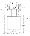
- Fig. 1 shows a first embodiment of an electric actuator 10 according to the invention, which serves to position at least one first, rotor-side assembly against at least one second, rotor-side assembly, wherein the electric actuator 10 of Fig. 1 an electric machine 11 and an actuator 12 has.
- the electric machine 11 has a stator or stator 13 with stator windings or stator windings 14 and a rotor or rotor 15, wherein the rotor or rotor 15 of the electric machine 11 with the actuator 12 in the embodiment of Fig. 1 is coupled via a rotor shaft 16.
- Fig. 1 is a system boundary 17 between rotating or rotor-side assemblies and standing or stator-side assemblies of the electric actuator 10 schematically shown by a dashed line, wherein according to Fig. 1 this system boundary 17 extends through an air gap 18 formed between the stator or stator 13 and the rotor or rotor 15 of the electric machine 11.
- the actuator 12 and the rotor or rotor 15 of the electric actuator 10 according to the invention are coupled together, namely such that in a first BestromungsPark the electric machine 11, namely the stator windings or stator windings 14 thereof, the rotor or rotor 15 of the electric Machine 11 and the actuator 12 rotate at an identical speed and in a second BestromungsTalk same at different speeds.
- the rotor or rotor 15 of the electric machine 11 and the actuator 12 rotate at an identical speed when the stator windings or stator windings 14 of the electric machine 11 are not energized.
- Such a positioning is carried out according to the invention only when the rotor or rotor 15 of the electric machine 11 and the actuator 12 rotate at a different speed, which is preferably the case when the stator windings or stator windings 14 of the stator 13 of the stator electric machine 11 are energized.
- a positioning of the or each first rotating assembly of the rotating system with respect to the or each second rotating assembly of the rotating system can be made, namely in the embodiment of Fig. 1 a rotating or rotational positioning of the respective modules to each other.
- Fig. 1 can be seen that the placement energy of the electric actuator 10, which is required to increase or reduce the rotational speed of the rotor 15 of the electric machine 11 relative to the rotational speed of the actuator 12 to provide a rotational speed difference between them to perform a positioning task by the air gap 18 of the electric machine 11 is transmitted, which is formed between the rotor or rotor 15 and the stator 13 of the electric machine 11.
- the point energy is therefore transmitted through the air gap 18 of the electric machine 11, so that no slip rings or rotary transformers or rotary feedthroughs for point energy transfer are required.
- the rotor or rotor 15 of the electric machine 11 and the actuator 12 have different rotational speeds ⁇ 1 and ⁇ 2, rotational positioning or displacement of the or each first rotating assembly of the rotating system relative to the or each second rotating assembly thereof.
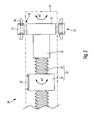
- FIG. 2 shows Fig. 2 an embodiment of an electric actuator 19, in which, when the rotor or rotor 15 of the electric machine 11 and the actuator 12 rotate at different speeds ⁇ 1 and ⁇ 2, a linear positioning at least a first rotor-side assembly of the rotating system against at least a second , the rotor-side assembly of the same can take place, namely the fact that the actuator 12 is formed by a threaded spindle 20 and a screw on the threaded spindle 20 at the rotational speed ⁇ 1 spindle nut 21, wherein the threaded spindle 20 via the rotor shaft 16 with the rotor 15 of the rotor electric machine 11 is coupled.
- Fig. 3 shows an embodiment of an actuator 10 according to the invention based on the embodiment of Fig. 1 , wherein in the embodiment of the Fig. 3 the electric machine 11 is designed as a permanent-magnetically excited synchronous machine, whose stator windings or stator windings 14 are assigned a contactor 23.
- the contactor 23 is energized and opened in the energized state, wherein when the contactor 23 closes in the short-circuited or de-energized state, the stator windings or stator windings 14 of the electric machine are short-circuited, thereby forming a short-circuit torque of the electric machine 11 can be used to build a speed difference between the rotor or rotor 15 of the electric machine 11 and the actuator 12 so as conditioned by the short-circuit torque of the electric machine 11, the respective first rotating assembly of the rotating system relative to the respective second, rotating Assemble the same assembly in a safety position.
- This safety positioning via a contactor can also be realized when the electric machine 11 is designed as an asynchronous machine.
- the contactor is then assigned a capacitor and optionally an electrical resistance, in which case the capacitor-excited asynchronous machine executes the safety positioning via a regenerative torque of the electric machine 11 in the event of a fault.
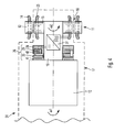
- FIG. 4 Another embodiment of an electric actuator 24 according to the invention based on the embodiment of Fig. 1 shows Fig. 4 , wherein in the embodiment of the Fig. 4 the electric machine 11 is designed as an asynchronous machine whose stator or stator 13 carries the stator windings or stator windings 14 and their rotor or rotor 15 rotor windings or rotor windings 25.
- An asynchronous machine has, as already mentioned, the stator windings or stator windings 14 in the stator or stator 13 and the rotor windings or rotor windings 25 in the rotor or rotor 15 of the electric machine 11. Distinguish the angular velocities of a flow of the stator or stator 13 and of the rotor or rotor 15 of the asynchronous machine, a voltage is induced in the rotor windings or rotor windings 25.
- the torque formation in the electric machine 11 designed as an asynchronous machine is linked to an actuation, preferably an opening, of the electromagnetically actuated, preferably electromagnetically opened, braking device 26.
- an AC voltage can be induced in the rotor windings or rotor windings 25, which can be used to energize a cooperating with the actuator 12 braking device 26 and consequently to open in particular.
- the rotor windings or rotor windings 25 of the rotor 15 of the electric machine 11 are coupled to a rectifier 27, which converts the alternating voltage induced in the rotor windings or rotor windings 25 into a DC voltage for energizing the braking device 26.
- the brake device 26 when the brake device 26 has a first BestromungsPark and is then open, it allows at a speed difference between the speeds ⁇ 1 and ⁇ 2 of rotor 15 of the electric machine 11 and actuator 12 to perform a linear and / or rotary positioning task .
- the braking device 26 when the braking device 26 has a second energizing state, in particular is not energized, and then closed in particular, it prevents this linear and / or rotational positioning, in that the braking device 26 in the closed state, the setting of an angular velocity difference ⁇ 1 and ⁇ 2 prevented.
- the rectifier 27 is integrated in the rotor shaft 16 and therefore designed as a rotating component.
- the brake device 26 has a brake magnet 28, a brake magnet coil 29, a brake disk 30 and a friction surface 41 cooperating with the brake disk 30 and associated with the actuator 12, and a spring element 42.
- the spring-loaded brake disc 30 is pressed by the spring element 42 against the actuator 12, namely the friction surface 41 assigned to it, so when the brake device 26 is closed no difference between the rotational speeds ⁇ 1 and ⁇ 2 build up and so positioning can not take place ,
- the brake device 26 can also be operated or energized with another actuator.
- electromagnetically actuated braking device 26 is an exemplary embodiment of the same. Instead of this electromagnetically actuated braking device 26, any positive or frictional holding device can be used, which prevents the positioning in a first state and in a second state permits the positioning.
- a non-electrically operated braking device which provides a permanent braking torque and blocks the actuator 12 due to the braking torque and only when the electric machine 11 applies a torque which can overcome this braking torque, the actuator 12 to perform a positioning task releases. In this case, then the electric machine 11 must be made larger.
- FIG. 5 Another embodiment of an actuator 31 according to the invention shows Fig. 5 , wherein the actuator 31 of the Fig. 5 as well as the actuator 19 of the Fig. 2 the execution of a linear positioning between rotor-side assemblies of a rotating system is used.
- Fig. 5 are the threaded spindle 20 associated with two sensors 32, by means of which the linear displacement of the threaded spindle 20 in the sense of the double arrow 22 can be detected or monitored, so on the basis of provided by the sensors 32 measuring signals to perform a positioning task the energization of the electric machine eleventh to control or regulate.
- a lock nut 33 which is coupled to the spindle nut 21 and with the rotor or rotor 15 of the electric machine 11, a stop in case of failure.
- An access to the actuator 31 is possible via an actuator 34 assigned to the rotor or rotor 15 in order to carry out manual auxiliary positioning of the rotating assemblies of the rotating system relative to one another, independently of the energization of the electric machine 11.
- FIG. 5 a stator-side housing 35 for the stator or stator 13 of the electric machine 11, which is supported by bearings 37 on a rotor-side intermediate flange 36 and a hollow shaft 38.
- the stator-side housing 35 is mounted directly on the rotating subsystem, so that can be dispensed with a complex attachment and their orientation.
- the actuating torque which acts on the stator-side housing 35, be derived or absorbed by a torque arm, wherein the torque arm is supported in the non-rotating system or anchored in the non-rotating system.
- the threaded spindle 20 is further associated with a rotary feedthrough 39, via which, for example, a fluid 40, in particular a hydraulic fluid, can be introduced or carried out in the rotating system.
- a fluid 40 in particular a hydraulic fluid
- a braking device 43 by means of which in the event of an error, a safety positioning analogous to the embodiment of Fig. 3 , but without the use of a contactor, can be realized.
- the braking device 43 is arranged between the housing 35 of the stator and the rotor 15 or rotor of the electric machine 11.
- the braking device 43 is electromagnetically actuated and has a brake magnet 44, a brake magnet coil 45, a brake disk 46 and a friction surface 47 cooperating with the brake disk 46 and a spring element 48.
- the braking device 43 In normal operation, preferably current actuated, the braking device 43 is opened. Upon the occurrence of a fault or failure of the opening performance, the spring element 38 presses the brake disk 46 against the friction surface 47 and thus generates a control torque analogous to the short-circuit torque in Fig. 3 which causes the angular velocity difference between the rotational speeds ⁇ 1 and ⁇ 2 required to reach a safe position until the angular velocity of the rotating system is equal to zero.
- the achievement of a z. B. for a wind turbine or a hydropower plant safe position of Rotorbeerielung or blading would thus be secured without power via the servo motor.
- All embodiments of the electric actuators according to the invention shown have in common that a placement energy for the actuator, which is required to slow down or acceleration of the rotor or rotor 15 of the electric machine 11 relative to an actuator 12 and thus to provide a speed difference between them, over the Air gap 18 of the electric machine 11 is transmitted. Then, if there is such a speed difference, the execution of a linear and / or rotating positioning task is possible. Then, if such a speed difference is not present, the execution of a linear and / or rotating positioning task is not possible.
- energy namely the product of the rotational speed ⁇ 2
- an actuating torque and a positioning time either supplied to the rotating system or discharged from the same. The removal of energy from the rotating system takes place in particular in the safety positioning on the contactor 23 of Fig. 3 or the braking device 43 of Fig. 5 ,
- the electric machines 11 may, as shown, be designed as internal rotor motors with cylindrical air gaps or as external rotor motors and as so-called pancake motors.
Landscapes
- Engineering & Computer Science (AREA)
- Power Engineering (AREA)
- Physics & Mathematics (AREA)
- Electromagnetism (AREA)
- Connection Of Motors, Electrical Generators, Mechanical Devices, And The Like (AREA)
Applications Claiming Priority (1)
| Application Number | Priority Date | Filing Date | Title |
|---|---|---|---|
| DE102009055708.3A DE102009055708B4 (de) | 2009-11-26 | 2009-11-26 | Elektrischer Stellantrieb |
Publications (3)
| Publication Number | Publication Date |
|---|---|
| EP2328261A2 true EP2328261A2 (fr) | 2011-06-01 |
| EP2328261A3 EP2328261A3 (fr) | 2017-01-18 |
| EP2328261B1 EP2328261B1 (fr) | 2020-01-08 |
Family
ID=43517789
Family Applications (1)
| Application Number | Title | Priority Date | Filing Date |
|---|---|---|---|
| EP10014735.4A Active EP2328261B1 (fr) | 2009-11-26 | 2010-11-18 | Actionneur électrique |
Country Status (2)
| Country | Link |
|---|---|
| EP (1) | EP2328261B1 (fr) |
| DE (1) | DE102009055708B4 (fr) |
Cited By (4)
| Publication number | Priority date | Publication date | Assignee | Title |
|---|---|---|---|---|
| WO2012175455A3 (fr) * | 2011-06-21 | 2014-05-30 | Ssb Duradrive Gmbh | Moteur électrique |
| CN108059065A (zh) * | 2017-12-28 | 2018-05-22 | 山西东辉新能源动力研究院有限公司 | 电梯及电梯组件 |
| JP2020010586A (ja) * | 2018-07-11 | 2020-01-16 | 株式会社ソシオリカ | 可変磁束界磁型同期発電機を有する風力発電システム |
| CN113785134A (zh) * | 2019-04-30 | 2021-12-10 | 采埃孚股份公司 | 离合器致动单元 |
Families Citing this family (2)
| Publication number | Priority date | Publication date | Assignee | Title |
|---|---|---|---|---|
| DE102015013290A1 (de) * | 2015-10-15 | 2017-04-20 | Sew-Eurodrive Gmbh & Co Kg | Antrieb, aufweisend einen von einem Umrichter über erste elektrische Leitungen gespeisten Elektromotor und eine Bremse und Verfahren zum Betreiben eines Antriebs |
| AT523262B1 (de) * | 2020-01-29 | 2021-07-15 | Manuel Schleiffelder Mag | Vorrichtung zur Verstellung der Neigung von Rotorblättern eines Rotors |
Family Cites Families (14)
| Publication number | Priority date | Publication date | Assignee | Title |
|---|---|---|---|---|
| US2370135A (en) * | 1941-09-25 | 1945-02-27 | Engineering & Res Corp | Variable pitch propeller |
| GB2022534B (en) * | 1978-04-20 | 1982-06-30 | Dowty Rotol Ltd | Bladed rotors |
| US4490093A (en) * | 1981-07-13 | 1984-12-25 | U.S. Windpower, Inc. | Windpower system |
| DE3232459A1 (de) * | 1982-09-01 | 1984-04-05 | Heinrich 4520 Melle Ruwe | Regelmechanismus fuer windkraftanlagen |
| DE3406634A1 (de) * | 1984-02-24 | 1985-08-29 | Grob-Werke GmbH & Co KG, 8948 Mindelheim | Vorrichtung zum verstellen des anstellwinkels einer luftschraube |
| DE4221783C2 (de) * | 1992-07-03 | 1994-06-16 | Klinger Friedrich Prof Dr Ing | Vorrichtung zur Verstellung von Rotorblättern |
| DE4320205A1 (de) * | 1993-06-18 | 1994-12-22 | Fichtel & Sachs Ag | Stellantrieb für eine Kraftfahrzeug-Reibungskupplung |
| DE29621247U1 (de) * | 1996-12-06 | 1997-01-23 | Moog GmbH, 71034 Böblingen | Elektromotorische Antriebseinrichtung für Schienenfahrzeuge |
| DE60027380T2 (de) * | 1999-10-07 | 2007-05-10 | ITT Mfg. Enterprises, Inc., Wilmington | Automatische Abschaltvorrichtung |
| FR2831225B1 (fr) * | 2001-10-24 | 2004-01-02 | Snecma Moteurs | Dispositif electrohydraulique de changement de pas d'helice |
| DE10335575B4 (de) * | 2003-07-31 | 2005-10-06 | Siemens Ag | Notbetriebseinrichtung zur Verstellung von Rotorblättern für eine Windkraftanlage |
| DE102006015511A1 (de) * | 2006-03-31 | 2007-10-04 | Robert Bosch Gmbh | Windkraftanlage |
| DE102006049490A1 (de) * | 2006-10-17 | 2008-04-24 | Lti Reenergy Gmbh | Ansteuerschaltung für Gleichstrommotoren mit Bremse und Notbetriebsversorgungseinrichtung |
| DE102006057213A1 (de) * | 2006-12-01 | 2008-06-05 | Robert Bosch Gmbh | Elektrische Antriebsvorrichtung |
-
2009
- 2009-11-26 DE DE102009055708.3A patent/DE102009055708B4/de active Active
-
2010
- 2010-11-18 EP EP10014735.4A patent/EP2328261B1/fr active Active
Non-Patent Citations (1)
| Title |
|---|
| None |
Cited By (5)
| Publication number | Priority date | Publication date | Assignee | Title |
|---|---|---|---|---|
| WO2012175455A3 (fr) * | 2011-06-21 | 2014-05-30 | Ssb Duradrive Gmbh | Moteur électrique |
| CN108059065A (zh) * | 2017-12-28 | 2018-05-22 | 山西东辉新能源动力研究院有限公司 | 电梯及电梯组件 |
| CN108059065B (zh) * | 2017-12-28 | 2024-02-13 | 山西东辉新能源汽车研究院有限公司 | 电梯及电梯组件 |
| JP2020010586A (ja) * | 2018-07-11 | 2020-01-16 | 株式会社ソシオリカ | 可変磁束界磁型同期発電機を有する風力発電システム |
| CN113785134A (zh) * | 2019-04-30 | 2021-12-10 | 采埃孚股份公司 | 离合器致动单元 |
Also Published As
| Publication number | Publication date |
|---|---|
| DE102009055708B4 (de) | 2025-11-13 |
| EP2328261A3 (fr) | 2017-01-18 |
| EP2328261B1 (fr) | 2020-01-08 |
| DE102009055708A1 (de) | 2011-06-01 |
Similar Documents
| Publication | Publication Date | Title |
|---|---|---|
| EP2328261B1 (fr) | Actionneur électrique | |
| EP2006557B1 (fr) | Procédé et dispositif de démarrage d'une machine électrique avoir un rotor avec un palier magnétique | |
| DE102016113117B4 (de) | Elektrischer Stellantrieb und Stellgerät mit einem elektrischen Stellantrieb | |
| DE102007000404B4 (de) | Steuervorrichtung für Bereichschaltmechanismus | |
| EP1509684B1 (fr) | Dispositif de reglage angulaire relatif de deux elements rotatifs | |
| EP2646636B1 (fr) | Dispositif de détermination de position | |
| EP2061141B1 (fr) | Machine électrique dotée de freins magnétiques directement sur le rotor | |
| EP1564868B1 (fr) | Machine électrique | |
| DE102017220941A1 (de) | Elektrische Maschine mit erhöhter Betriebssicherheit | |
| WO2005119898A2 (fr) | Moteur a courant continu sans balais | |
| EP3152831B1 (fr) | Procédé et dispositif de déplacement d'un organe de réglage d'un système d'actionneur équipé d'un servomoteur à commutation électronique | |
| EP3499694B1 (fr) | Frein à aimant permanent et procédé de génération d'un couple de freinage ou de maintien au moyen d'un frein à aimant permanent | |
| EP3655685B1 (fr) | Dispositif de réglage à fonction de réglage de sécurité | |
| EP3900159B1 (fr) | Moteur électrique à différents points neutres | |
| WO1987001526A1 (fr) | Unite de regulation electrique | |
| EP1501185B1 (fr) | Méthode et dispositif pour positionner un dispositif rotatif | |
| EP0761925A1 (fr) | Dispositif de frein pour un rideau coupe-fumée, rideau coupe-feu ou rideau similaire | |
| EP1960852B1 (fr) | Dispositif de contrôle pour un dispositif d'entraînement | |
| EP3449564B1 (fr) | Procédé et dispositif de commande d'une machine électrique | |
| DE202008010748U1 (de) | Verstelleinrichtung für eine Windenergieanlage | |
| EP3959486B1 (fr) | Procédé de réglage de la position d'un actionneur après une interruption de l'alimentation électrique | |
| DE102017218571B4 (de) | Verfahren zum Betreiben einer Kraftfahrzeuggetriebepumpe | |
| DE102007046242A1 (de) | Verfahren zur Ansteuerung eines EC-Motors | |
| EP4568860B1 (fr) | Étrier de frein compact avec actionneur électromécanique, entraînement d'arbre excentrique et réglage mécanique, et procédé de fonctionnement d'un tel étrier de frein compact | |
| DE102022130919A1 (de) | Antriebseinheit für einen Lüfter mit einer Drehzahlcodierung basierend auf einer selektiven Energieübertragung über zwei getrennte elektrische Anschlussleitungssysteme |
Legal Events
| Date | Code | Title | Description |
|---|---|---|---|
| PUAI | Public reference made under article 153(3) epc to a published international application that has entered the european phase |
Free format text: ORIGINAL CODE: 0009012 |
|
| AK | Designated contracting states |
Kind code of ref document: A2 Designated state(s): AL AT BE BG CH CY CZ DE DK EE ES FI FR GB GR HR HU IE IS IT LI LT LU LV MC MK MT NL NO PL PT RO RS SE SI SK SM TR |
|
| AX | Request for extension of the european patent |
Extension state: BA ME |
|
| PUAL | Search report despatched |
Free format text: ORIGINAL CODE: 0009013 |
|
| AK | Designated contracting states |
Kind code of ref document: A3 Designated state(s): AL AT BE BG CH CY CZ DE DK EE ES FI FR GB GR HR HU IE IS IT LI LT LU LV MC MK MT NL NO PL PT RO RS SE SI SK SM TR |
|
| AX | Request for extension of the european patent |
Extension state: BA ME |
|
| RIC1 | Information provided on ipc code assigned before grant |
Ipc: F03D 7/02 20060101ALI20161209BHEP Ipc: H02K 7/06 20060101AFI20161209BHEP Ipc: H02K 7/102 20060101ALI20161209BHEP |
|
| RAP1 | Party data changed (applicant data changed or rights of an application transferred) |
Owner name: KREBS & AULICH GMBH |
|
| STAA | Information on the status of an ep patent application or granted ep patent |
Free format text: STATUS: REQUEST FOR EXAMINATION WAS MADE |
|
| 17P | Request for examination filed |
Effective date: 20170714 |
|
| RBV | Designated contracting states (corrected) |
Designated state(s): AL AT BE BG CH CY CZ DE DK EE ES FI FR GB GR HR HU IE IS IT LI LT LU LV MC MK MT NL NO PL PT RO RS SE SI SK SM TR |
|
| GRAP | Despatch of communication of intention to grant a patent |
Free format text: ORIGINAL CODE: EPIDOSNIGR1 |
|
| STAA | Information on the status of an ep patent application or granted ep patent |
Free format text: STATUS: GRANT OF PATENT IS INTENDED |
|
| INTG | Intention to grant announced |
Effective date: 20190628 |
|
| GRAS | Grant fee paid |
Free format text: ORIGINAL CODE: EPIDOSNIGR3 |
|
| GRAA | (expected) grant |
Free format text: ORIGINAL CODE: 0009210 |
|
| STAA | Information on the status of an ep patent application or granted ep patent |
Free format text: STATUS: THE PATENT HAS BEEN GRANTED |
|
| AK | Designated contracting states |
Kind code of ref document: B1 Designated state(s): AL AT BE BG CH CY CZ DE DK EE ES FI FR GB GR HR HU IE IS IT LI LT LU LV MC MK MT NL NO PL PT RO RS SE SI SK SM TR |
|
| REG | Reference to a national code |
Ref country code: GB Ref legal event code: FG4D Free format text: NOT ENGLISH |
|
| REG | Reference to a national code |
Ref country code: CH Ref legal event code: EP |
|
| REG | Reference to a national code |
Ref country code: IE Ref legal event code: FG4D Free format text: LANGUAGE OF EP DOCUMENT: GERMAN |
|
| REG | Reference to a national code |
Ref country code: DE Ref legal event code: R096 Ref document number: 502010016441 Country of ref document: DE |
|
| REG | Reference to a national code |
Ref country code: AT Ref legal event code: REF Ref document number: 1223890 Country of ref document: AT Kind code of ref document: T Effective date: 20200215 |
|
| REG | Reference to a national code |
Ref country code: NL Ref legal event code: MP Effective date: 20200108 |
|
| REG | Reference to a national code |
Ref country code: LT Ref legal event code: MG4D |
|
| PG25 | Lapsed in a contracting state [announced via postgrant information from national office to epo] |
Ref country code: NO Free format text: LAPSE BECAUSE OF FAILURE TO SUBMIT A TRANSLATION OF THE DESCRIPTION OR TO PAY THE FEE WITHIN THE PRESCRIBED TIME-LIMIT Effective date: 20200408 Ref country code: FI Free format text: LAPSE BECAUSE OF FAILURE TO SUBMIT A TRANSLATION OF THE DESCRIPTION OR TO PAY THE FEE WITHIN THE PRESCRIBED TIME-LIMIT Effective date: 20200108 Ref country code: LT Free format text: LAPSE BECAUSE OF FAILURE TO SUBMIT A TRANSLATION OF THE DESCRIPTION OR TO PAY THE FEE WITHIN THE PRESCRIBED TIME-LIMIT Effective date: 20200108 Ref country code: RS Free format text: LAPSE BECAUSE OF FAILURE TO SUBMIT A TRANSLATION OF THE DESCRIPTION OR TO PAY THE FEE WITHIN THE PRESCRIBED TIME-LIMIT Effective date: 20200108 Ref country code: PT Free format text: LAPSE BECAUSE OF FAILURE TO SUBMIT A TRANSLATION OF THE DESCRIPTION OR TO PAY THE FEE WITHIN THE PRESCRIBED TIME-LIMIT Effective date: 20200531 Ref country code: NL Free format text: LAPSE BECAUSE OF FAILURE TO SUBMIT A TRANSLATION OF THE DESCRIPTION OR TO PAY THE FEE WITHIN THE PRESCRIBED TIME-LIMIT Effective date: 20200108 |
|
| PG25 | Lapsed in a contracting state [announced via postgrant information from national office to epo] |
Ref country code: BG Free format text: LAPSE BECAUSE OF FAILURE TO SUBMIT A TRANSLATION OF THE DESCRIPTION OR TO PAY THE FEE WITHIN THE PRESCRIBED TIME-LIMIT Effective date: 20200408 Ref country code: LV Free format text: LAPSE BECAUSE OF FAILURE TO SUBMIT A TRANSLATION OF THE DESCRIPTION OR TO PAY THE FEE WITHIN THE PRESCRIBED TIME-LIMIT Effective date: 20200108 Ref country code: SE Free format text: LAPSE BECAUSE OF FAILURE TO SUBMIT A TRANSLATION OF THE DESCRIPTION OR TO PAY THE FEE WITHIN THE PRESCRIBED TIME-LIMIT Effective date: 20200108 Ref country code: IS Free format text: LAPSE BECAUSE OF FAILURE TO SUBMIT A TRANSLATION OF THE DESCRIPTION OR TO PAY THE FEE WITHIN THE PRESCRIBED TIME-LIMIT Effective date: 20200508 Ref country code: GR Free format text: LAPSE BECAUSE OF FAILURE TO SUBMIT A TRANSLATION OF THE DESCRIPTION OR TO PAY THE FEE WITHIN THE PRESCRIBED TIME-LIMIT Effective date: 20200409 Ref country code: HR Free format text: LAPSE BECAUSE OF FAILURE TO SUBMIT A TRANSLATION OF THE DESCRIPTION OR TO PAY THE FEE WITHIN THE PRESCRIBED TIME-LIMIT Effective date: 20200108 |
|
| REG | Reference to a national code |
Ref country code: DE Ref legal event code: R097 Ref document number: 502010016441 Country of ref document: DE |
|
| PG25 | Lapsed in a contracting state [announced via postgrant information from national office to epo] |
Ref country code: SK Free format text: LAPSE BECAUSE OF FAILURE TO SUBMIT A TRANSLATION OF THE DESCRIPTION OR TO PAY THE FEE WITHIN THE PRESCRIBED TIME-LIMIT Effective date: 20200108 Ref country code: DK Free format text: LAPSE BECAUSE OF FAILURE TO SUBMIT A TRANSLATION OF THE DESCRIPTION OR TO PAY THE FEE WITHIN THE PRESCRIBED TIME-LIMIT Effective date: 20200108 Ref country code: EE Free format text: LAPSE BECAUSE OF FAILURE TO SUBMIT A TRANSLATION OF THE DESCRIPTION OR TO PAY THE FEE WITHIN THE PRESCRIBED TIME-LIMIT Effective date: 20200108 Ref country code: SM Free format text: LAPSE BECAUSE OF FAILURE TO SUBMIT A TRANSLATION OF THE DESCRIPTION OR TO PAY THE FEE WITHIN THE PRESCRIBED TIME-LIMIT Effective date: 20200108 Ref country code: RO Free format text: LAPSE BECAUSE OF FAILURE TO SUBMIT A TRANSLATION OF THE DESCRIPTION OR TO PAY THE FEE WITHIN THE PRESCRIBED TIME-LIMIT Effective date: 20200108 Ref country code: CZ Free format text: LAPSE BECAUSE OF FAILURE TO SUBMIT A TRANSLATION OF THE DESCRIPTION OR TO PAY THE FEE WITHIN THE PRESCRIBED TIME-LIMIT Effective date: 20200108 Ref country code: ES Free format text: LAPSE BECAUSE OF FAILURE TO SUBMIT A TRANSLATION OF THE DESCRIPTION OR TO PAY THE FEE WITHIN THE PRESCRIBED TIME-LIMIT Effective date: 20200108 |
|
| PLBE | No opposition filed within time limit |
Free format text: ORIGINAL CODE: 0009261 |
|
| STAA | Information on the status of an ep patent application or granted ep patent |
Free format text: STATUS: NO OPPOSITION FILED WITHIN TIME LIMIT |
|
| 26N | No opposition filed |
Effective date: 20201009 |
|
| PG25 | Lapsed in a contracting state [announced via postgrant information from national office to epo] |
Ref country code: IT Free format text: LAPSE BECAUSE OF FAILURE TO SUBMIT A TRANSLATION OF THE DESCRIPTION OR TO PAY THE FEE WITHIN THE PRESCRIBED TIME-LIMIT Effective date: 20200108 |
|
| PG25 | Lapsed in a contracting state [announced via postgrant information from national office to epo] |
Ref country code: PL Free format text: LAPSE BECAUSE OF FAILURE TO SUBMIT A TRANSLATION OF THE DESCRIPTION OR TO PAY THE FEE WITHIN THE PRESCRIBED TIME-LIMIT Effective date: 20200108 Ref country code: SI Free format text: LAPSE BECAUSE OF FAILURE TO SUBMIT A TRANSLATION OF THE DESCRIPTION OR TO PAY THE FEE WITHIN THE PRESCRIBED TIME-LIMIT Effective date: 20200108 |
|
| PG25 | Lapsed in a contracting state [announced via postgrant information from national office to epo] |
Ref country code: MC Free format text: LAPSE BECAUSE OF FAILURE TO SUBMIT A TRANSLATION OF THE DESCRIPTION OR TO PAY THE FEE WITHIN THE PRESCRIBED TIME-LIMIT Effective date: 20200108 |
|
| REG | Reference to a national code |
Ref country code: CH Ref legal event code: PL |
|
| GBPC | Gb: european patent ceased through non-payment of renewal fee |
Effective date: 20201118 |
|
| PG25 | Lapsed in a contracting state [announced via postgrant information from national office to epo] |
Ref country code: LU Free format text: LAPSE BECAUSE OF NON-PAYMENT OF DUE FEES Effective date: 20201118 |
|
| REG | Reference to a national code |
Ref country code: BE Ref legal event code: MM Effective date: 20201130 |
|
| PG25 | Lapsed in a contracting state [announced via postgrant information from national office to epo] |
Ref country code: CH Free format text: LAPSE BECAUSE OF NON-PAYMENT OF DUE FEES Effective date: 20201130 Ref country code: LI Free format text: LAPSE BECAUSE OF NON-PAYMENT OF DUE FEES Effective date: 20201130 |
|
| PG25 | Lapsed in a contracting state [announced via postgrant information from national office to epo] |
Ref country code: IE Free format text: LAPSE BECAUSE OF NON-PAYMENT OF DUE FEES Effective date: 20201118 Ref country code: FR Free format text: LAPSE BECAUSE OF NON-PAYMENT OF DUE FEES Effective date: 20201130 |
|
| PG25 | Lapsed in a contracting state [announced via postgrant information from national office to epo] |
Ref country code: GB Free format text: LAPSE BECAUSE OF NON-PAYMENT OF DUE FEES Effective date: 20201118 |
|
| REG | Reference to a national code |
Ref country code: AT Ref legal event code: MM01 Ref document number: 1223890 Country of ref document: AT Kind code of ref document: T Effective date: 20201118 |
|
| PG25 | Lapsed in a contracting state [announced via postgrant information from national office to epo] |
Ref country code: AT Free format text: LAPSE BECAUSE OF NON-PAYMENT OF DUE FEES Effective date: 20201118 |
|
| PG25 | Lapsed in a contracting state [announced via postgrant information from national office to epo] |
Ref country code: TR Free format text: LAPSE BECAUSE OF FAILURE TO SUBMIT A TRANSLATION OF THE DESCRIPTION OR TO PAY THE FEE WITHIN THE PRESCRIBED TIME-LIMIT Effective date: 20200108 Ref country code: MT Free format text: LAPSE BECAUSE OF FAILURE TO SUBMIT A TRANSLATION OF THE DESCRIPTION OR TO PAY THE FEE WITHIN THE PRESCRIBED TIME-LIMIT Effective date: 20200108 Ref country code: CY Free format text: LAPSE BECAUSE OF FAILURE TO SUBMIT A TRANSLATION OF THE DESCRIPTION OR TO PAY THE FEE WITHIN THE PRESCRIBED TIME-LIMIT Effective date: 20200108 |
|
| PG25 | Lapsed in a contracting state [announced via postgrant information from national office to epo] |
Ref country code: MK Free format text: LAPSE BECAUSE OF FAILURE TO SUBMIT A TRANSLATION OF THE DESCRIPTION OR TO PAY THE FEE WITHIN THE PRESCRIBED TIME-LIMIT Effective date: 20200108 Ref country code: AL Free format text: LAPSE BECAUSE OF FAILURE TO SUBMIT A TRANSLATION OF THE DESCRIPTION OR TO PAY THE FEE WITHIN THE PRESCRIBED TIME-LIMIT Effective date: 20200108 |
|
| PG25 | Lapsed in a contracting state [announced via postgrant information from national office to epo] |
Ref country code: BE Free format text: LAPSE BECAUSE OF NON-PAYMENT OF DUE FEES Effective date: 20201130 |
|
| REG | Reference to a national code |
Ref country code: DE Ref legal event code: R081 Ref document number: 502010016441 Country of ref document: DE Owner name: MOTION MAKERS GMBH, DE Free format text: FORMER OWNER: KREBS & AULICH GMBH, 38855 WERNIGERODE, DE |
|
| PGFP | Annual fee paid to national office [announced via postgrant information from national office to epo] |
Ref country code: DE Payment date: 20251127 Year of fee payment: 16 |