EP2329584B1 - Handwerkzeugmaschine mit bürstenmotor - Google Patents
Handwerkzeugmaschine mit bürstenmotor Download PDFInfo
- Publication number
- EP2329584B1 EP2329584B1 EP09780209A EP09780209A EP2329584B1 EP 2329584 B1 EP2329584 B1 EP 2329584B1 EP 09780209 A EP09780209 A EP 09780209A EP 09780209 A EP09780209 A EP 09780209A EP 2329584 B1 EP2329584 B1 EP 2329584B1
- Authority
- EP
- European Patent Office
- Prior art keywords
- brush holder
- brush
- power tool
- hand power
- motor housing
- Prior art date
- Legal status (The legal status is an assumption and is not a legal conclusion. Google has not performed a legal analysis and makes no representation as to the accuracy of the status listed.)
- Not-in-force
Links
- 239000002184 metal Substances 0.000 claims description 6
- 210000002105 tongue Anatomy 0.000 claims 4
- 238000010276 construction Methods 0.000 description 5
- 230000008859 change Effects 0.000 description 4
- 238000004519 manufacturing process Methods 0.000 description 3
- 230000008901 benefit Effects 0.000 description 2
- 238000007789 sealing Methods 0.000 description 2
- 240000006829 Ficus sundaica Species 0.000 description 1
- 238000009825 accumulation Methods 0.000 description 1
- 230000009471 action Effects 0.000 description 1
- 230000032683 aging Effects 0.000 description 1
- 239000003245 coal Substances 0.000 description 1
- 230000006835 compression Effects 0.000 description 1
- 238000007906 compression Methods 0.000 description 1
- 239000000428 dust Substances 0.000 description 1
- 238000005516 engineering process Methods 0.000 description 1
- 238000000034 method Methods 0.000 description 1
- 230000037361 pathway Effects 0.000 description 1
- 230000008569 process Effects 0.000 description 1
- 230000001681 protective effect Effects 0.000 description 1
- 230000008439 repair process Effects 0.000 description 1
- 238000004804 winding Methods 0.000 description 1
Images


Classifications
-
- H—ELECTRICITY
- H02—GENERATION; CONVERSION OR DISTRIBUTION OF ELECTRIC POWER
- H02K—DYNAMO-ELECTRIC MACHINES
- H02K5/00—Casings; Enclosures; Supports
- H02K5/04—Casings or enclosures characterised by the shape, form or construction thereof
- H02K5/14—Means for supporting or protecting brushes or brush holders
- H02K5/143—Means for supporting or protecting brushes or brush holders for cooperation with commutators
- H02K5/148—Slidably supported brushes
-
- H—ELECTRICITY
- H02—GENERATION; CONVERSION OR DISTRIBUTION OF ELECTRIC POWER
- H02K—DYNAMO-ELECTRIC MACHINES
- H02K13/00—Structural associations of current collectors with motors or generators, e.g. brush mounting plates or connections to windings; Disposition of current collectors in motors or generators; Arrangements for improving commutation
- H02K13/10—Arrangements of brushes or commutators specially adapted for improving commutation
-
- H—ELECTRICITY
- H02—GENERATION; CONVERSION OR DISTRIBUTION OF ELECTRIC POWER
- H02K—DYNAMO-ELECTRIC MACHINES
- H02K7/00—Arrangements for handling mechanical energy structurally associated with dynamo-electric machines, e.g. structural association with mechanical driving motors or auxiliary dynamo-electric machines
- H02K7/14—Structural association with mechanical loads, e.g. with hand-held machine tools or fans
- H02K7/145—Hand-held machine tool
Definitions
- the present invention is based on a hand tool according to the preamble of claim 1.
- a hand tool is in
- Electric hand tools are today commonly used by universal electric motors, i. driven by collector or brush motors.
- current is transferred from the power cable via brushes to the rotor of the rotor which rotates during operation for commutation.
- the brushes are spatially fixed in the housing by means of a brush holder. This consists of a rectangular shaft, which leads the rectangular brush axially. It is provided with a spring which pushes the brush towards the collector.
- the brush wears at its contact point due to sliding friction on the collector and moves under the action of the spring according to the loss of length due to wear axially towards the collector. As a result, the current flow between the collector and brush can be maintained.
- Known electric hand tool motors are provided with two brushes and therefore have two brush holder, which may be arranged individually in the housing or sitting opposite each other on a support plate which is fixable in the housing.
- brush holders with tabs are known, with which, for example, the brush cable, an electronics unit, the field coils, etc. are electrically contacted.
- the spring is arranged with respect to the motor axis behind or next to the brush. This spiral spring / clockspring are mostly used. In other constructions, a compression spring is placed axially over the brush. This increases the length of the brush and the radial projection of the cover of the brush holder system, the circumference of the motor housing. The associated comfort and safety loss must be taken into account when the motor housing serves as a handle.
- the space of the motor housing can be used effectively and thus the hand tool can be made smaller, e.g. with reduced handle diameter and shorter length.
- a service opening of the motor housing on the seat of the new brush holder and also its lid be sized relatively small and also a directionaldom be arranged for the screw fastening of the lid.
- the brush holder according to the invention is a single brush holder that is individually mounted independently of other brush holders in the device and which, for example, not sitting with other brush holders on a common support plate, the assembly or a brush change is simplified.
- the shaft of the brush holder was rotated from its - according to the prior art centered position - by an angle ⁇ about the longitudinal axis or offset, so that an optimal application of force Spring can be reached on the brush over the entire brush life. Due to the described angular offset of the shaft about the longitudinal axis, the spring can be positioned next to the screw dome.
- the plug contacts of the brush holder move up, near the housing periphery to the center and axially further forward in the motor housing.
- the space of the device is used more effectively and the housing is shorter and lighter.
- the electrical leads and are easier to install are provided laterally next to the brush holder through which the field lines are guided in the rear region of the motor housing during assembly of the field winding.
- the motor housing in the area of the brush holder for the arrangement of a service opening or a cover would have a considerable additional design and manufacturing technology Effort must be changed in order to obtain stability, strength and vibration behavior of the motor housing and thus the entire device.
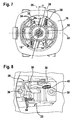
- the spring in addition to the inclined position of the shaft, the spring, in particular its spiral roller, can be arranged inclined to the shaft, see Fig. 7 , Due to the inclination of the spring this can be passed even more convenient at the mounting of the brush holder on the screw dome.
- the improved space utilization is given both with and without service opening. Due to the inclination of the shaft, the plug contacts are arranged more centrally, the width of the brush holder is reduced overall. In this case, the plug contact of the brush cable such an ample distance to the shaft, preferably 8 mm, that the brush cable is not a security risk even with aging and accumulation of electrically conductive dust, s. Fig. 8 ,
- the oblique arrangement of the brush or the shaft of the brush holder remains without influence on production and assembly of the power tool, since only the brush holder has been changed.
- the change consists solely in the fact that the shaft obliquely instead of previously rectangular joined to the support plate of the brush holder, in particular with a crimp connection.
- the spring seat of the brush holder is to be aligned so that the spring arm rests centrally in the shaft and centrally acting axially on the brush and provides for their mechanical and electrical optimal support on the collector. This ensures a secure electrical contact with low friction between brush and collector.
- the brush holder can be easily inserted from above through the service opening in the device and screwed or otherwise fixed, for. by means of locking lugs. He is thus automatically arranged at an angle ⁇ , without adjustment would be necessary.
- the new motor housing can be made without cost increase.
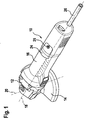
- FIG. 1 An in FIG. 1 Spatially illustrated hand tool machine is designed as an angle grinder 10 and has the front, in viewing direction left, a gear housing 12, which consists of metal. For this occurs down, parallel to the vertical axis 20 of the angle grinder 10, an unillustrated output shaft for receiving an unillustrated grinding wheel, which is encompassed by a protective hood 14. Rear is flanged to the gear housing 12, a longitudinal axis 18 of the angle grinder 10 defining motor housing 16 in pot construction. This takes a customary for hand tools universal motor, ie an electric motor 50 ( Fig. 7 ) with collector 52 on. From the motor housing 16, a cable 26 comes to the rear for powering the motor 50.
- a gear housing 12 which consists of metal. For this occurs down, parallel to the vertical axis 20 of the angle grinder 10, an unillustrated output shaft for receiving an unillustrated grinding wheel, which is encompassed by a protective hood 14.
- Rear is flanged to the gear housing 12, a longitudinal axis
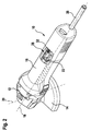
- the motor housing 16 carries on its top center a cover 24 a service opening 23 ( Fig. 2 ), which is bolted to the motor housing 16 with a cover screw 25 konturbmony. Diametrically opposite to the cover 24 is on the bottom of the motor housing 16 - not visible- a same cover 24 for sealing the lower service opening 23 for the second brush holder arranged so that the power supply of the motor 50 is secured as usual via two offset by 180 ° brushes ,
- FIG. 2 the angle grinder 10 is shown with or without open lid 24 from above with view of the service opening 23, the details according to FIG. 1 and furthermore, a brush holder 28 and a screw dome 32 can be seen. These are present on the underside of the motor housing 16 in the same configuration and shown even more clearly in the following figures.
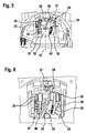
- FIG. 3 shown enlarged side view of the motor housing 16 with the open service opening 23 after FIG. 2 shows the brush holder 28 with an adjoining spring 30, which sits on a spring axis 42, which is characterized by a form of a support plate 40, Fig. 9 , is formed.
- the spring 30 engages with a parallel to the longitudinal axis 18 forward facing spring arm 31 centrally from above into a shaft 38, which serves as a longitudinal guide of a brush or coal 39.
- a bent out of the support plate 40 eyelet 36 of the brush holder 28 is fixed by means of a screw, not shown, or by means of Matterrastnocken on the motor housing 16.
- a perpendicular or parallel to the vertical axis 20 of a rib 33 of the motor housing 16 projecting screw dome 32 is used to engage the cover screw 25 for konturbillionen, sealing attachment of the lid 24 ( Fig. 1 ) on the motor housing 16.
- the spring 30 is arranged laterally at a distance from the screw dome 32. Further, tabs 34 are seated with cable clamps 35 for a brush cable 46 ( Fig. 6 ) recognizable.
- FIG. 4 shown enlarged plan view of the open motor housing 16 with a variant of the brush holder 28 according to the invention shows its central attachment means eyelet 36 in the motor housing 16 and offset from the middle shaft 38 of the brush holder 28 with the seated on the spring axis 42, obliquely arranged spring 30 and the spring arm 31 without a brush with the collector 52 underneath and the screw dome 32. Further, a tongue 34 with a cable clamp 35 of a not shown brush cable as part of the brush holder 28 can be seen.
- FIG. 5 An in FIG. 5 shown, enlarged rear view after FIG. 3 shows the view of the open motor housing 16 with the transversely disposed rib 33, the screw dome 32 for fixing the lid 24 (FIG. Fig. 1 ) wearing.
- the arrangement of the brush holder 28 is shown, ie its central attachment by means of eyelet 36 in the motor housing 16 and offset from the center, erected in a vertical projection to the longitudinal axis 18 shaft 38 of the brush holder 28 with the seated on the spring axis 42 spring 30 and the spring arm 31 without a brush with the undetectable collector 52.
- two tabs 34, each with a cable clamp 35 of a not shown brush cable as part of the brush holder 28 can be seen.
- FIG. 6 enlarged rear view similar FIG. 3 shows in contrast to FIG. 5 the service opening 23 with a connected to the brush holder 28, multiply bent brush cable 46 and a straight brush cable 47 with cable clamps 35, further in the chess 38 stuck brush 39 and a screw 37 for fixing the brush holder 28 on the motor housing 16th
- FIG. 7 shown cross section of the motor housing 16 with collector 52 and brush holder 28 after FIG. 2 clearly shows the angular axis offset from the 20, radially aligned to the longitudinal axis 18 arrangement of the shaft 38 of the brush holder 28, the transverse axis 22 and the tabs 34 and the screw 37th
- FIG. 8 illustrated a variant of a side view of the open service opening according to Fig. 2 from another viewing angle illustrates again the Brush holder 28 as a sheet metal construction and the details mentioned above, without listing them again individually.
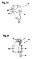
- FIGS. 9a to 9g in its six 90 ° side projections and in a perspective view.
- a detail brush holder 28 with spring 30 is designed as a sheet metal construction, with a support plate 40 is angled or punched several times and I crimped the U-shaped bent sheet metal of the shaft 38 absorbs.
- the brush holder 28 may also be made of plastic with inserted electrical pathways.
- hand-held power tool described as angle grinder and a hand drill, scraper, orbital sander, jigsaw, etc. with a designed as a handle motor housing with the brush holder according to the invention, with or without service opening and lid, be equipped.
Landscapes
- Engineering & Computer Science (AREA)
- Power Engineering (AREA)
- Motor Or Generator Current Collectors (AREA)
- Motor Or Generator Frames (AREA)
Description
- Die vorliegende Erfindung geht aus von einer Handwerkzeugmaschine nach dem Oberbegriff des Anspruchs 1. Eine solche Handwerkzeugmaschine ist in
-
EP 1911 547 A2 beschrieben. - Elektro-Handwerkzeugmaschinen werden heute üblicherweise von elektrischen Universalmotoren, d.h. von Kollektor- bzw. Bürsten-Motoren angetrieben. Dabei wird für die Kommutierung Strom vom Stromkabel über Bürsten auf den im Betrieb drehenden Kollektor des Rotors übertragen. Die Bürsten sind im Gehäuse mittels Bürstenhalters räumlich fixiert. Dieser besteht aus einem rechteckigen Schacht, der die rechteckige Bürste axial führt. Er ist mit einer Feder versehen, die die Bürste zum Kollektor hin drückt. Die Bürste nutzt sich an ihrer Kontaktstelle infolge Gleitreibung am Kollektor ab und bewegt sich unter der Wirkung der Feder entsprechend dem Längenverlust durch Abnutzung axial zum Kollektor hin. Dadurch kann der Stromfluss zwischen Kollektor und Bürste aufrechterhalten werden.
- Bekannte Elektrohandwerkzeugmotoren sind mit zwei Bürsten versehen und haben daher auch zwei Bürstenhalter, die einzeln im Gehäuse angeordnet sein können oder einander gegenüberliegend auf einer Trägerplatte sitzen, die im Gehäuse fixierbar ist.
- Dabei sind Bürstenhalter mit Steckzungen bekannt, mit denen beispielsweise das Bürstenkabel, eine Elektronikeinheit, die Feldspulen usw. elektrisch kontaktierbar sind.
- Die Feder ist in Bezug auf die Motorachse hinter oder neben der Bürste angeordnet. Dabei kommen meistens Spiralfeder/Uhrwerksfeder zur Anwendung. Bei anderen Konstruktionen wird eine Druckfeder axial über der Bürste angeordnet. Dies vergrößert die Baulänge der Bürste und durch den radialen Überstand des Deckels des Bürstenhaltersystems den Umfang des Motorgehäuses. Die damit verbundene Komfort- und Sicherheitseinbuße muss in Kauf genommen werden, wenn das Motorgehäuse als Handgriff dient.
- Vorteil der Erfindung mit den Merkmalen des Anspruchs 1 ist, dass bei Verwendung des neuen Bürstenhalters der Bauraum des Motorgehäuses effektiver nutzbar ist und damit die Handwerkzeugmaschine kleiner gebaut werden kann, z.B. mit verringertem Griffdurchmesser und geringerer Länge.
- Außerdem kann eine Serviceöffnung des Motorgehäuses am Sitz des neuen Bürstenhalters und auch ihr Deckel relativ klein bemessen sein und zudem ein Schraubdom für die Schraubbefestigung des Deckels angeordnet werden. Je kleiner die Serviceöffnung ist, umso stabiler/steifer ist das damit versehene Motorgehäuse bzw. der Deckel.
- Dadurch, dass der erfindungsgemäße Bürstenhalter ein Einzel-Bürstenhalter ist, der individuell, unabhängig von anderen Bürstenhaltern im Gerät montierbar ist und der beispielsweise nicht mit weiteren Bürstenhaltern auf einer gemeinsamen Trägerplatte sitzt, ist die Montage bzw. ein Bürstenwechsel vereinfacht.
- Bei geöffnetem Deckel ist der Bürstenhalter frei zugänglich, so dass ohne Demontage weiterer Gerätekomponenten der Federarm abgehoben, die abgenutzte Bürste entnommen und eine neue Bürste eingesetzt werden kann. Damit ist ein Bürstenwechsel und auch ein Bürstenhalterwechsel einfach und bequem zu erledigen.
- Der bei Verwendung einer Serviceöffnung für den Deckel nötige mittige Schraubdom begrenzt den Bauraum des Bürstenhalters. Bei konventioneller Bauweise des Bürstenhalters wäre dieser Schraubdom einer sich axial nach hinten erstreckenden Feder im Wege gewesen und hätte so nicht realisiert werden können. Daher wurde erfindungsgemäß die Feder so am Bürstenhalter positioniert dass sie neben dem Schraubdom angeordnet ist. Die mittige Position des Schraubdoms am Gehäuse dient dabei der optimalen Krafteinleitung der Deckelschraube in den Deckel und verhilft der Handwerkzeugmaschine damit zu einer symmetrischen Gestalt und damit intuitiv sicherer Handhabung.
- Um die Feder neben dem Schraubendom positionieren zu können, wurde der Schacht des Bürstenhalters aus seiner - gemäß dem Stand der Technik mittigen Position - um einen Winkel α um die Längsachse gedreht bzw. versetzt, damit eine optimale Krafteinleitung der Feder auf die Bürste über die gesamte Bürstenlebensdauer erreicht werden kann. Durch den beschriebenen Winkelversatz des Schachts um die Längsachse kann die Feder neben dem Schraubendom positioniert werden.
- Durch die außermittige Positionierung des Schachts verlagern sich auch die Steckkontakte des Bürstenhalters oben, nahe des Gehäuseumfangs zur Mitte und axial weiter nach vorn im Motorgehäuse. Dadurch wird der Bauraum des Gerätes effektiver genutzt und das Gehäuse kürzer und leichter. Weiter können dadurch die elektrischen Anschlußleitungen gekürzt werden und sind leichter montierbar. Bei der erfindungsgemäßen Geräteausführung sind seitlich neben dem Bürstenhalter zwei Öffnungen im Motorgehäuse vorhanden, durch die hindurch bei der Montage der Feldwicklung die Feldleitungen in den hinteren Bereich des Motorgehäuses geführt werden.
- Wäre der Schacht des Bürstenhalters nicht seitlich aus der Mittenanordnung und winklig versetzt um dadurch die Steckkontakte näher zur Mittellinie oben auf dem Motorgehäuse hin zu bekommen, hätte das Motorgehäuse im Bereich des Bürstenhalters für die Anordnung einer Serviceöffnung bzw. eines Deckels konstruktiv und herstellungstechnisch mit erheblichem zusätzlichem Aufwand geändert werden müssen, um Stabilität, Festigkeit und Schwingungsverhalten des Motorgehäuses und damit des gesamten Gerätes zu erhalten.
- Bei einer weiteren Variante des Bürstenhalters kann neben der Schrägstellung des Schachts die Feder, insbesondere ihre Spiralrolle, geneigt zum Schacht angeordnet werden, siehe
Fig. 7 . Durch die Schrägstellung der Feder kann diese bei der Montage des Bürstenhalters noch bequemer am Schraubdom vorbeigeführt werden. - Die verbesserte Bauraumausnutzung ist sowohl mit als auch ohne Serviceöffnung gegeben. Durch die Schrägstellung des Schachts sind die Steckkontakte weiter mittig angeordnet sind, wird die Breite des Bürstenhalters insgesamt verringert. Dabei hat der Steckkontakt des Bürstenkabels einen derart reichlichen Abstand zum Schacht, vorzugsweise 8 mm, dass das Bürstenkabel auch bei Alterung und Häufung elektrisch leitenden Staubs nicht zum Sicherheitsrisiko wird, s.
Fig. 8 . - Die schiefe Anordnung der Bürste bzw. des Schachts des Bürstenhalters bleibt ohne Einfluß auf Herstellung und Montage der Handwerkzeugmaschine, da allein der Bürstenhalter geändert wurde. Die Änderung besteht allein darin, dass der Schacht schiefwinklig statt bisher rechtwinklig an das Trägerblech des Bürstenhalters gefügt ist, insbesondere mit einer Crimp-Verbindung. Dabei ist die Federaufnahme des Bürstenhalters so auszurichten, dass der Federarm mittig im Schacht einliegt und mittig axial beaufschlagend auf die Bürste trifft und für deren mechanisch und elektrisch optimale Abstützung am Kollektor sorgt. Damit ist ein sicherer elektrischer Kontakt bei geringer Reibung zwischen Bürste und Kollektor gewährleistet.
- Bei der Montage der Handwerkzeugmaschine bzw. bei Reparaturen kann der Bürstenhalter ohne weiteres von oben durch die Serviceöffnung in das Gerät gesteckt und verschraubt oder anderweitig fixiert werden, z.B. mittels Rastnasen. Er ist damit automatisch unter einem Winkel α angeordnet, ohne dass ein Justieren nötig wäre.
- Dadurch dass das Motorgehäuse durch die Erfindung nur so geändert wird, dass die Entformung bei der Herstellung des Motorgehäuses unverändert unter einem 90°-Winkel erfolgt, kann das neue Motorgehäuse ohne Kostenerhöhung hergestelt werden.
- Nachstehend ist die Erfindung anhand eines Ausführungsbeispiels mit zugehöriger Zeichnung näher erläutert. Es zeigen
- Figur 1
- einen erfindungsgemäßen Winkelschleifer mit Serviceöffnung und Deckel
- Figur 2
- den Winkelschleifer nach
Figur 1 mit offener Serviceöffnung - Figur 3
- eine vergrößerte Seitenansicht der offenen Serviceöffnung nach
Fig. 2 - Figur 4
- eine Draufsicht auf eine Variante des Bürstenhalters bei geöffnetem Gehäuses
- Figur 5
- eine Hinteransicht nach
Figur 4 - Figur 6
- eine Hinteransicht ähnlich
Figur 3 mit mehrfach gebogenem Bürstenkabel - Figur 7
- einen Querschnitt des Motorgehäuses mit Kollektor und Bürstenhalter nach
Fig. 2 - Figur 8
- eine Variante einer Seitenansicht der offenen Serviceöffnung gemäß
Fig. 2 und - Figur 9a bis f
- den Bürstenhalter als Einzelheit in seinen sechs 90°-Seitenprojektionen und in einer perspektivischen Ansicht.
- Eine in
Figur 1 räumlich dargestellte Handwerkzeugmaschine ist als Winkelschleifer 10 ausgestaltet und hat vorn, in Betrachtungsrichtung links, ein Getriebegehäuse 12, das aus Metall besteht. Aus diesem tritt nach unten, parallel zur Hochachse 20 des Winkelschleifers 10 eine nichtdargestellte Abtriebswelle zur Aufnahme einer nichtdargestellten Schleifscheibe, die von einer Schutzhaube 14 umgriffen wird. Hinten ist an das Getriebegehäuse 12 ein eine Längsachse 18 des Winkelschleifers 10 definierendes Motorgehäuse 16 in Topfbauweise angeflanscht. Dieses nimmt einen für Handwerkzeugmaschinen üblichen Universalmotor, d.h. einen elektrischen Motor 50 (Fig. 7 ) mit Kollektor 52 auf. Aus dem Motorgehäuse 16 tritt hinten ein Kabel 26 zur Stromversorgung des Motors 50 aus. - Das Motorgehäuse 16 trägt auf seiner Oberseite mittig einen Deckel 24 einer Serviceöffnung 23 (
Fig. 2 ), der mit einer Deckelschraube 25 konturbündig an das Motorgehäuse 16 geschraubt ist. Diametral entgegengesetzt zum Deckel 24 ist auf der Unterseite des Motorgehäuses 16 - nicht sichtbar- ein gleicher Deckel 24 zur Abdichtung der unteren Serviceöffnung 23 für den zweiten Bürstenhalter angeordnet, so dass die Stromversorgung des Motors 50 wie üblich über zwei um 180 ° versetzte Bürsten gesichert ist. - In
Figur 2 ist der Winkelschleifer 10 ohne bzw. mit geöffnetem Deckel 24 von oben mit Ansicht der Serviceöffnung 23 gezeigt, wobei die Einzelheiten gemäßFigur 1 und darüber hinaus ein Bürstenhalter 28 und ein Schraubdom 32 erkennbar sind. Diese sind auf der Unterseite des Motorgehäuses 16 in gleicher Ausgestaltung vorhanden und in den nachfolgenden Figuren noch deutlicher dargestellt. - Eine in
Figur 3 dargestellte vergrößerte Seitenansicht des Motorgehäuses 16 mit der offenen Serviceöffnung 23 nachFigur 2 zeigt den Bürstenhalter 28 mit einer dahinter aneordneten Feder 30, die auf einer Federachse 42 sitzt, die durch eine Ausprägung eines Trägerblechs 40,Fig. 9 , gebildet wird. Die Feder 30 greift mit einem parallel zur Längsachse 18 nach vorn weisenden Federarm 31 mittig von oben in einen Schacht 38, der als Längsführung einer Bürste bzw. Kohle 39 dient. Eine aus dem Trägerblech 40 herausgebogene Öse 36 des Bürstenhalters 28 ist mittels einer nicht dargestellten Schraube oder mittels Überrastnocken am Motorgehäuse 16 fixiert. Ein senkrecht bzw. parallel zur Hochachse 20 aus einer Rippe 33 des Motorgehäuses 16 ragender Schraubdom 32 dient zum Eingriff der Deckelschraube 25 zur konturbündigen, abdichtenden Befestigung des Deckels 24 (Fig. 1 ) am Motorgehäuse 16. Dabei ist die Feder 30 seitlich in einem Abstand zum Schraubdom 32 angeordnet. Weiter sind Steckzungen 34 mit daran sitzenden Kabelklemmen 35 für ein Bürstenkabel 46 (Fig. 6 ) erkennbar. - Eine in
Figur 4 dargestellte vergrößerte Draufsicht des geöffneten Motorgehäuses 16 mit einer Variante des erfindungsgemäßen Bürstenhalters 28 zeigt dessen mittige Befestigung mittels Öse 36 im Motorgehäuse 16 und den aus der Mitte versetzten Schacht 38 des Bürstenhalters 28 mit der auf der Federachse 42 sitzenden, schief angeordneten Feder 30 und dem Federarm 31 ohne Bürste mit dem darunter erkennbaren Kollektor 52 sowie den Schraubdom 32. Weiter ist eine Steckzunge 34 mit einer Kabelklemme 35 eines nichtdargestellten Bürstenkabels als Bestandteil des Bürstenhalters 28 erkennbar. - Eine in
Figur 5 dargestellte, vergrößerte Hinteransicht nachFigur 3 zeigt den Blick auf das geöffnete Motorgehäuse 16 mit der quer angeordneten Rippe 33, die den Schraubdom 32 zum Fixieren des Deckels 24 (Fig. 1 ) trägt. Weiter ist die Anordnung des Bürstenhalters 28 gezeigt, d.h. dessen mittige Befestigung mittels Öse 36 im Motorgehäuse 16 und den aus der Mitte versetzten, in senkrechter Projektion zu Längsachse 18 aufgerichteten Schacht 38 des Bürstenhalters 28 mit der auf der Federachse 42 sitzenden Feder 30 und dem Federarm 31 ohne Bürste mit dem darunter erkennbaren Kollektor 52. Weiter sind zwei Steckzungen 34 mit je einer Kabelklemme 35 eines nichtdargestellten Bürstenkabels als Bestandteil des Bürstenhalters 28 erkennbar. - Die in
Figur 6 dargestellte, vergrößerte Hinteransicht ähnlichFigur 3 zeigt im Unterschied zuFigur 5 die Serviceöffnung 23 mit einem an den Bürstenhalter 28 angeschlossenen, mehrfach gebogenen Bürstenkabel 46 und einem geraden Bürstenkabel 47 mit Kabelklemmen 35, weiter eine im Schach 38 steckende Bürste 39 und eine Schraube 37 zum Fixieren des Bürstenhalters 28 am Motorgehäuse 16. - Der in
Figur 7 dargestellte Querschnitt des Motorgehäuses 16 mit Kollektor 52 und Bürstenhalter 28 nachFigur 2 zeigt deutlich die von der Hochachse 20 um winkelversetzte, radial zur Längsachse 18 ausgerichtete Anordnung des Schachts 38 des Bürstenhalters 28, dessen Querachse 22 und die Steckzungen 34 sowie die Schraube 37. - Die in
Figur 8 dargestellte eine Variante einer Seitenansicht der offenen Serviceöffnung gemäßFig. 2 aus einem weiteren Betrachtungswinkel verdeutlicht nochmals den Bürstenhalter 28 als Blechkonstruktion sowie die zuvor genannten Einzelheiten, ohne diese nochmals einzeln aufzuführen. - Der in den
Figuren 9a bis 9g in seinen sechs 90°-Seitenprojektionen und in einer perspektivischen Ansicht.als Einzelheit dargestellte Bürstenhalter 28 mit Feder 30 ist als Blechkonstruktion ausgeführt, wobei ein Trägerblech 40 mehrfach abgewinkelt bzw. gestanzt ist und ich einer Krimpverbindung das u-förmig gebogene Blech des Schachts 38 aufnimmt. - Abgewinkelte Endbereiche des Trägerblechs 40 bilden dabei einstückig die Federachse 42, die Steckzungen 34 und die Öse 36.
- Der Bürstenhalter 28 kann auch aus Kunststoff mit eingelegten elektrischen Leitungsbahnen ausgeführt sein.
- Statt der als Winkelschleifer beschriebenen Handwerkzeugmaschine kann auch eine Handbohrmaschine, Schaber, Exzenterschleifer, Stichsäge usw. mit einem als Handgriff gestalteten Motorgehäuse mit dem erfindungsgemäßen Bürstenhalter, mit oder ohne Serviceöffnung und Deckel, ausgestattet sein.
Claims (10)
- Handwerkzeugmaschine (10) mit einem länglichen, insbesondere als Handgriff dienenden, Motorgehäuse (16), das einen elektrischen Kollektormotor (50) aufnimmt, wobei die Bürsten (39) federbeaufschlagt in einem Bürstenhalter (28) mit Bürstenschacht (38) gelagert sind, der allein/einzeln im Motorgehäuse (16) fixiert ist, dem ein Achskreuz zuordenbar ist, insbesondere eine Längs-(18) eine Hoch- (20) und eine Querachse (22), dadurch gekennzeichnet, dass der Schacht (38) des Bürstenhalters (28) gegenüber der Hochachse (20) des Motorgehäuses (16) um einen Winkel von ca. 20° seitlich versetzt angeordnet ist, insbesondere radial zur Längsachse (18) ausgerichtet.
- Handwerkzeugmaschine nach Anspruch 1, dadurch gekennzeichnet, dass zwei singuläre Bürstenhalter (28) einander diametral gegenüberliegend am Motorgehäuse (16) angeordnet sind.
- Handwerkzeugmaschine nach Anspruch 1 oder 2, dadurch gekennzeichnet, dass beide Schächte (38) der Bürstenhalter (28) um gleiche Winkel in gleicher Richtung zur Hochachse (20) versetzt angeordnet sind.
- Handwerkzeugmaschine nach Anspruch 1, dadurch gekennzeichnet, dass eine am Bürstenhalter (28) sitzende Spiralfeder (30) mit einem Federarm (31) zur Federbeaufschlagung der Bürste (39) dient und dass eine von der Spiralfeder (30) gebildete Mittenebene im wesentlichen parallel zur Längsachse (18) verläuft.
- Handwerkzeugmaschine nach Anspruch 4, dadurch gekennzeichnet, dass die von der Spiralfeder (30) gebildete Mittenebene gegenüber dem Schacht (38) seitlich geneigt angeordnet ist und dass die Spiralfeder (30) neben dem Schraubdom (32) sitzt.
- Handwerkzeugmaschine nach Anspruch 5, dadurch gekennzeichnet, dass der Bürstenhalter (28) mit mindestens einer Steckzunge (34) zum Anschluss eines Bürstenkabels (46) versehen ist, wobei jede der Steckzungen (34) einen elektrischen Sicherheits-Mindestabstand, vorzugsweise von 8 mm zur Serviceöffnung (23), zur Öse (36) sowie zum Schraubdom (32) hat.
- Handwerkzeugmaschine nach Anspruch 5, dadurch gekennzeichnet, dass der Bürstenhalter (28) aus dem gemeinsamen, ebenen Trägerblech (40) herausgebogene Steckzungen (34) hat, wobei zwei in vertikaler und eine in horizontaler Ebene verlaufen.
- Handwerkzeugmaschine nach Anspruch 5, dadurch gekennzeichnet, dass der Bürstenhalter (28) eine aus dem Trägerblech (40) abgewinkelte Öse (36) zum Fixieren des Bürstenhalters (28), insbesondere zum Anschrauben, am Motorgehäuse (16) hat.
- Handwerkzeugmaschine nach Anspruch 5, dadurch gekennzeichnet, dass der Schraubdom (32) für die Fixierung eines die Serviceöffnung (23) schließenden Deckels (24) auf der Oberseite des Motorgehäuses (16), insbesondere auf einer Rippe (33) zentrisch und in einem elektrischen Sicherheits-Mindestabstand, vorzugsweise von 8 mm, zu stromführenden Teilen des Bürstenhalters (28) angeordnet ist.
- Handwerkzeugmaschine nach einem der vorhergehenden Ansprüche, dadurch gekennzeichnet, dass der Bürstenhalter (28) Metallblech besteht, insbesondere aus einem mehrfach abgewinkelten Trägerblech (40), an den der Schacht (28) als u-förmig gebogenes Blechstück befestigbar ist, insbesondere über eine Krimpverbindung.
Applications Claiming Priority (2)
| Application Number | Priority Date | Filing Date | Title |
|---|---|---|---|
| DE102008041716A DE102008041716A1 (de) | 2008-08-29 | 2008-08-29 | Handwerkzeugmaschine mit Bürstenmotor |
| PCT/EP2009/058543 WO2010023008A1 (de) | 2008-08-29 | 2009-07-07 | Handwerkzeugmaschine mit bürstenmotor |
Publications (2)
| Publication Number | Publication Date |
|---|---|
| EP2329584A1 EP2329584A1 (de) | 2011-06-08 |
| EP2329584B1 true EP2329584B1 (de) | 2012-11-21 |
Family
ID=41134658
Family Applications (1)
| Application Number | Title | Priority Date | Filing Date |
|---|---|---|---|
| EP09780209A Not-in-force EP2329584B1 (de) | 2008-08-29 | 2009-07-07 | Handwerkzeugmaschine mit bürstenmotor |
Country Status (6)
| Country | Link |
|---|---|
| US (1) | US8487503B2 (de) |
| EP (1) | EP2329584B1 (de) |
| CN (1) | CN102138274B (de) |
| DE (1) | DE102008041716A1 (de) |
| RU (1) | RU2506683C2 (de) |
| WO (1) | WO2010023008A1 (de) |
Families Citing this family (6)
| Publication number | Priority date | Publication date | Assignee | Title |
|---|---|---|---|---|
| DE102007057033A1 (de) * | 2007-11-27 | 2009-05-28 | Robert Bosch Gmbh | Elektrisch antreibbare Handwerkzeugmaschine |
| DE102009026516A1 (de) * | 2009-05-27 | 2010-12-02 | Robert Bosch Gmbh | Werkzeugmaschine, insbesondere Handwerkzeugmaschine |
| US9143015B2 (en) * | 2012-05-23 | 2015-09-22 | Black & Decker Inc. | Brush holder for a brush assembly for a power tool motor |
| DE102016013907A1 (de) * | 2016-11-22 | 2018-05-24 | Andreas Stihl Ag & Co. Kg | Handgeführtes Arbeitsgerät |
| DE102016225984A1 (de) * | 2016-12-22 | 2018-06-28 | Robert Bosch Gmbh | Bürstenhalter für eine elektrische Maschine |
| US11296471B2 (en) | 2019-08-22 | 2022-04-05 | Ati Industrial Automation, Inc. | Motor brush quick change assembly |
Family Cites Families (13)
| Publication number | Priority date | Publication date | Assignee | Title |
|---|---|---|---|---|
| SU1171907A1 (ru) * | 1983-08-29 | 1985-08-07 | Всесоюзный Научно-Исследовательский И Проектно-Конструкторский Институт Механизированного И Ручного Строительно-Монтажного Инструмента,Вибраторов И Строительно-Отделочных Машин | Электрическа машина |
| DE4003029A1 (de) * | 1990-02-02 | 1991-08-08 | Bosch Gmbh Robert | Handgefuehrte werkzeugmaschine mit radialgeblaese |
| US5047679A (en) * | 1990-08-30 | 1991-09-10 | Baader Edward J | Casing for a small motor assembly |
| DE9401357U1 (de) * | 1994-01-27 | 1994-04-14 | BT Magnet-Technologie GmbH, 44629 Herne | Elektrische Kommutatormaschine |
| GB2323717B (en) * | 1997-02-27 | 1999-06-02 | Bosch Gmbh Robert | A hand tool machine |
| DE29716245U1 (de) * | 1997-09-10 | 1999-01-21 | Robert Bosch Gmbh, 70469 Stuttgart | Elektrohandwerkzeugmaschine |
| JP3676956B2 (ja) * | 1999-11-19 | 2005-07-27 | 株式会社マキタ | 電動工具及びその組み付け方法 |
| RU2203441C2 (ru) * | 2001-04-10 | 2003-04-27 | Колган Юрий Никитович | Электроинструмент с предохранительной муфтой |
| US6664701B1 (en) * | 2002-06-13 | 2003-12-16 | Black & Decker Inc. | Brush assembly |
| CH695974A5 (de) * | 2002-10-15 | 2006-10-31 | Team Orion Europe Sa | Gleichstrommotor mit Kollektor und Kohlebüsten. |
| DE10248921A1 (de) * | 2002-10-17 | 2004-05-13 | C. & E. Fein Gmbh & Co Kg | Elektrowerkzeug |
| US8087977B2 (en) * | 2005-05-13 | 2012-01-03 | Black & Decker Inc. | Angle grinder |
| US7988538B2 (en) * | 2006-10-13 | 2011-08-02 | Black & Decker Inc. | Large angle grinder |
-
2008
- 2008-08-29 DE DE102008041716A patent/DE102008041716A1/de not_active Withdrawn
-
2009
- 2009-07-07 US US12/737,909 patent/US8487503B2/en not_active Expired - Fee Related
- 2009-07-07 EP EP09780209A patent/EP2329584B1/de not_active Not-in-force
- 2009-07-07 WO PCT/EP2009/058543 patent/WO2010023008A1/de not_active Ceased
- 2009-07-07 RU RU2011111582/07A patent/RU2506683C2/ru not_active IP Right Cessation
- 2009-07-07 CN CN200980134007.XA patent/CN102138274B/zh not_active Expired - Fee Related
Also Published As
| Publication number | Publication date |
|---|---|
| US8487503B2 (en) | 2013-07-16 |
| US20110175466A1 (en) | 2011-07-21 |
| WO2010023008A1 (de) | 2010-03-04 |
| CN102138274A (zh) | 2011-07-27 |
| DE102008041716A1 (de) | 2010-03-04 |
| EP2329584A1 (de) | 2011-06-08 |
| RU2506683C2 (ru) | 2014-02-10 |
| RU2011111582A (ru) | 2012-10-10 |
| CN102138274B (zh) | 2014-12-10 |
Similar Documents
| Publication | Publication Date | Title |
|---|---|---|
| EP2329584B1 (de) | Handwerkzeugmaschine mit bürstenmotor | |
| EP1057239B1 (de) | Elektrischer getriebemotor für fahrzeugaggregate | |
| EP0778655B1 (de) | Verstellvorrichtung für die Kohlebürsten an einem Elektromotor | |
| DE102016106556A1 (de) | Hand-Werkzeugmaschine mit einem Absaugschlauch | |
| DE3629634C2 (de) | ||
| DE102008041717A1 (de) | Handwerkzeugmaschine mit Bürstenmotor | |
| DE102010062727A1 (de) | Elektromotorantrieb | |
| DE102007026106B4 (de) | Elektrohandwerkzeugmaschine mit einer drehbaren Bürstenplatte | |
| DE4027176C2 (de) | ||
| EP0489866A1 (de) | Schleifring- bzw. kommutatormotor. | |
| EP3246127A1 (de) | Hand-werkzeugmaschine mit einer positionierfederanordnung | |
| DE69818791T3 (de) | Elektrische Lüftereinheit für Kraftfahrzeugklimaanlage | |
| DE102004041490A1 (de) | Schleifkörperhalter | |
| EP1742332B1 (de) | Verstellvorrichtung zur Drehrichtungsumkehr | |
| DE102009001714A1 (de) | Elektrischer Antriebsmotor, insbesondere für ein Aggregat in einem Kraftfahrzeug | |
| EP0101546B1 (de) | Elektromotor, insbesondere zum Antreiben von Hilfsaggregaten in Kraftfahrzeugen | |
| EP1717931A2 (de) | Motor-Schalter-Anordnung einer Handwerkzeugmaschine | |
| EP2269270B1 (de) | Handwerkzeugmachine mit einer Steckeranordnung. | |
| EP2472679B1 (de) | Bürstenanordnung in einer Kommutatoreinrichtung in einer elektrischen Maschine | |
| EP2005556B1 (de) | Kunststoffelement | |
| EP2443726B1 (de) | Elektrische maschine sowie verstellantrieb | |
| EP0195929A2 (de) | Handwerkzeugmaschine mit einem Elektromotor | |
| DE29821736U1 (de) | Handwerkzeugmaschine | |
| DE10035254B4 (de) | Verschlußelement für das Gehäuse des Motors eines Kraftfahrzeuganlassers und Anlasser mit einem solchen Verschlußelement | |
| DE69602143T2 (de) | Gehäuse für ein elektrisches Bauteil |
Legal Events
| Date | Code | Title | Description |
|---|---|---|---|
| PUAI | Public reference made under article 153(3) epc to a published international application that has entered the european phase |
Free format text: ORIGINAL CODE: 0009012 |
|
| 17P | Request for examination filed |
Effective date: 20110329 |
|
| AK | Designated contracting states |
Kind code of ref document: A1 Designated state(s): AT BE BG CH CY CZ DE DK EE ES FI FR GB GR HR HU IE IS IT LI LT LU LV MC MK MT NL NO PL PT RO SE SI SK SM TR |
|
| AX | Request for extension of the european patent |
Extension state: AL BA RS |
|
| DAX | Request for extension of the european patent (deleted) | ||
| GRAP | Despatch of communication of intention to grant a patent |
Free format text: ORIGINAL CODE: EPIDOSNIGR1 |
|
| GRAS | Grant fee paid |
Free format text: ORIGINAL CODE: EPIDOSNIGR3 |
|
| GRAA | (expected) grant |
Free format text: ORIGINAL CODE: 0009210 |
|
| AK | Designated contracting states |
Kind code of ref document: B1 Designated state(s): AT BE BG CH CY CZ DE DK EE ES FI FR GB GR HR HU IE IS IT LI LT LU LV MC MK MT NL NO PL PT RO SE SI SK SM TR |
|
| REG | Reference to a national code |
Ref country code: GB Ref legal event code: FG4D Free format text: NOT ENGLISH |
|
| REG | Reference to a national code |
Ref country code: CH Ref legal event code: EP |
|
| REG | Reference to a national code |
Ref country code: AT Ref legal event code: REF Ref document number: 585503 Country of ref document: AT Kind code of ref document: T Effective date: 20121215 |
|
| REG | Reference to a national code |
Ref country code: IE Ref legal event code: FG4D Free format text: LANGUAGE OF EP DOCUMENT: GERMAN |
|
| REG | Reference to a national code |
Ref country code: DE Ref legal event code: R096 Ref document number: 502009005463 Country of ref document: DE Effective date: 20130117 |
|
| REG | Reference to a national code |
Ref country code: RO Ref legal event code: EPE |
|
| REG | Reference to a national code |
Ref country code: NL Ref legal event code: VDEP Effective date: 20121121 |
|
| REG | Reference to a national code |
Ref country code: LT Ref legal event code: MG4D |
|
| PG25 | Lapsed in a contracting state [announced via postgrant information from national office to epo] |
Ref country code: NO Free format text: LAPSE BECAUSE OF FAILURE TO SUBMIT A TRANSLATION OF THE DESCRIPTION OR TO PAY THE FEE WITHIN THE PRESCRIBED TIME-LIMIT Effective date: 20130221 Ref country code: LT Free format text: LAPSE BECAUSE OF FAILURE TO SUBMIT A TRANSLATION OF THE DESCRIPTION OR TO PAY THE FEE WITHIN THE PRESCRIBED TIME-LIMIT Effective date: 20121121 Ref country code: FI Free format text: LAPSE BECAUSE OF FAILURE TO SUBMIT A TRANSLATION OF THE DESCRIPTION OR TO PAY THE FEE WITHIN THE PRESCRIBED TIME-LIMIT Effective date: 20121121 Ref country code: ES Free format text: LAPSE BECAUSE OF FAILURE TO SUBMIT A TRANSLATION OF THE DESCRIPTION OR TO PAY THE FEE WITHIN THE PRESCRIBED TIME-LIMIT Effective date: 20130304 Ref country code: SE Free format text: LAPSE BECAUSE OF FAILURE TO SUBMIT A TRANSLATION OF THE DESCRIPTION OR TO PAY THE FEE WITHIN THE PRESCRIBED TIME-LIMIT Effective date: 20121121 |
|
| PG25 | Lapsed in a contracting state [announced via postgrant information from national office to epo] |
Ref country code: SI Free format text: LAPSE BECAUSE OF FAILURE TO SUBMIT A TRANSLATION OF THE DESCRIPTION OR TO PAY THE FEE WITHIN THE PRESCRIBED TIME-LIMIT Effective date: 20121121 Ref country code: GR Free format text: LAPSE BECAUSE OF FAILURE TO SUBMIT A TRANSLATION OF THE DESCRIPTION OR TO PAY THE FEE WITHIN THE PRESCRIBED TIME-LIMIT Effective date: 20130222 Ref country code: PT Free format text: LAPSE BECAUSE OF FAILURE TO SUBMIT A TRANSLATION OF THE DESCRIPTION OR TO PAY THE FEE WITHIN THE PRESCRIBED TIME-LIMIT Effective date: 20130321 Ref country code: LV Free format text: LAPSE BECAUSE OF FAILURE TO SUBMIT A TRANSLATION OF THE DESCRIPTION OR TO PAY THE FEE WITHIN THE PRESCRIBED TIME-LIMIT Effective date: 20121121 Ref country code: PL Free format text: LAPSE BECAUSE OF FAILURE TO SUBMIT A TRANSLATION OF THE DESCRIPTION OR TO PAY THE FEE WITHIN THE PRESCRIBED TIME-LIMIT Effective date: 20121121 |
|
| PG25 | Lapsed in a contracting state [announced via postgrant information from national office to epo] |
Ref country code: DK Free format text: LAPSE BECAUSE OF FAILURE TO SUBMIT A TRANSLATION OF THE DESCRIPTION OR TO PAY THE FEE WITHIN THE PRESCRIBED TIME-LIMIT Effective date: 20121121 Ref country code: SK Free format text: LAPSE BECAUSE OF FAILURE TO SUBMIT A TRANSLATION OF THE DESCRIPTION OR TO PAY THE FEE WITHIN THE PRESCRIBED TIME-LIMIT Effective date: 20121121 Ref country code: BG Free format text: LAPSE BECAUSE OF FAILURE TO SUBMIT A TRANSLATION OF THE DESCRIPTION OR TO PAY THE FEE WITHIN THE PRESCRIBED TIME-LIMIT Effective date: 20130221 Ref country code: CZ Free format text: LAPSE BECAUSE OF FAILURE TO SUBMIT A TRANSLATION OF THE DESCRIPTION OR TO PAY THE FEE WITHIN THE PRESCRIBED TIME-LIMIT Effective date: 20121121 Ref country code: EE Free format text: LAPSE BECAUSE OF FAILURE TO SUBMIT A TRANSLATION OF THE DESCRIPTION OR TO PAY THE FEE WITHIN THE PRESCRIBED TIME-LIMIT Effective date: 20121121 |
|
| PG25 | Lapsed in a contracting state [announced via postgrant information from national office to epo] |
Ref country code: IT Free format text: LAPSE BECAUSE OF FAILURE TO SUBMIT A TRANSLATION OF THE DESCRIPTION OR TO PAY THE FEE WITHIN THE PRESCRIBED TIME-LIMIT Effective date: 20121121 Ref country code: NL Free format text: LAPSE BECAUSE OF FAILURE TO SUBMIT A TRANSLATION OF THE DESCRIPTION OR TO PAY THE FEE WITHIN THE PRESCRIBED TIME-LIMIT Effective date: 20121121 |
|
| PLBE | No opposition filed within time limit |
Free format text: ORIGINAL CODE: 0009261 |
|
| STAA | Information on the status of an ep patent application or granted ep patent |
Free format text: STATUS: NO OPPOSITION FILED WITHIN TIME LIMIT |
|
| 26N | No opposition filed |
Effective date: 20130822 |
|
| PG25 | Lapsed in a contracting state [announced via postgrant information from national office to epo] |
Ref country code: HR Free format text: LAPSE BECAUSE OF FAILURE TO SUBMIT A TRANSLATION OF THE DESCRIPTION OR TO PAY THE FEE WITHIN THE PRESCRIBED TIME-LIMIT Effective date: 20121121 |
|
| REG | Reference to a national code |
Ref country code: DE Ref legal event code: R097 Ref document number: 502009005463 Country of ref document: DE Effective date: 20130822 |
|
| BERE | Be: lapsed |
Owner name: ROBERT BOSCH G.M.B.H. Effective date: 20130731 |
|
| PG25 | Lapsed in a contracting state [announced via postgrant information from national office to epo] |
Ref country code: MC Free format text: LAPSE BECAUSE OF FAILURE TO SUBMIT A TRANSLATION OF THE DESCRIPTION OR TO PAY THE FEE WITHIN THE PRESCRIBED TIME-LIMIT Effective date: 20121121 |
|
| REG | Reference to a national code |
Ref country code: CH Ref legal event code: PL |
|
| REG | Reference to a national code |
Ref country code: IE Ref legal event code: MM4A |
|
| PG25 | Lapsed in a contracting state [announced via postgrant information from national office to epo] |
Ref country code: CH Free format text: LAPSE BECAUSE OF NON-PAYMENT OF DUE FEES Effective date: 20130731 Ref country code: LI Free format text: LAPSE BECAUSE OF NON-PAYMENT OF DUE FEES Effective date: 20130731 Ref country code: BE Free format text: LAPSE BECAUSE OF NON-PAYMENT OF DUE FEES Effective date: 20130731 |
|
| PG25 | Lapsed in a contracting state [announced via postgrant information from national office to epo] |
Ref country code: IE Free format text: LAPSE BECAUSE OF NON-PAYMENT OF DUE FEES Effective date: 20130707 |
|
| PG25 | Lapsed in a contracting state [announced via postgrant information from national office to epo] |
Ref country code: SM Free format text: LAPSE BECAUSE OF FAILURE TO SUBMIT A TRANSLATION OF THE DESCRIPTION OR TO PAY THE FEE WITHIN THE PRESCRIBED TIME-LIMIT Effective date: 20121121 |
|
| PG25 | Lapsed in a contracting state [announced via postgrant information from national office to epo] |
Ref country code: MT Free format text: LAPSE BECAUSE OF FAILURE TO SUBMIT A TRANSLATION OF THE DESCRIPTION OR TO PAY THE FEE WITHIN THE PRESCRIBED TIME-LIMIT Effective date: 20121121 Ref country code: CY Free format text: LAPSE BECAUSE OF FAILURE TO SUBMIT A TRANSLATION OF THE DESCRIPTION OR TO PAY THE FEE WITHIN THE PRESCRIBED TIME-LIMIT Effective date: 20121121 Ref country code: TR Free format text: LAPSE BECAUSE OF FAILURE TO SUBMIT A TRANSLATION OF THE DESCRIPTION OR TO PAY THE FEE WITHIN THE PRESCRIBED TIME-LIMIT Effective date: 20121121 |
|
| PG25 | Lapsed in a contracting state [announced via postgrant information from national office to epo] |
Ref country code: MK Free format text: LAPSE BECAUSE OF FAILURE TO SUBMIT A TRANSLATION OF THE DESCRIPTION OR TO PAY THE FEE WITHIN THE PRESCRIBED TIME-LIMIT Effective date: 20121121 Ref country code: HU Free format text: LAPSE BECAUSE OF FAILURE TO SUBMIT A TRANSLATION OF THE DESCRIPTION OR TO PAY THE FEE WITHIN THE PRESCRIBED TIME-LIMIT; INVALID AB INITIO Effective date: 20090707 Ref country code: LU Free format text: LAPSE BECAUSE OF NON-PAYMENT OF DUE FEES Effective date: 20130707 |
|
| REG | Reference to a national code |
Ref country code: AT Ref legal event code: MM01 Ref document number: 585503 Country of ref document: AT Kind code of ref document: T Effective date: 20140707 |
|
| PG25 | Lapsed in a contracting state [announced via postgrant information from national office to epo] |
Ref country code: AT Free format text: LAPSE BECAUSE OF NON-PAYMENT OF DUE FEES Effective date: 20140707 |
|
| PG25 | Lapsed in a contracting state [announced via postgrant information from national office to epo] |
Ref country code: IS Free format text: LAPSE BECAUSE OF FAILURE TO SUBMIT A TRANSLATION OF THE DESCRIPTION OR TO PAY THE FEE WITHIN THE PRESCRIBED TIME-LIMIT Effective date: 20121121 |
|
| REG | Reference to a national code |
Ref country code: FR Ref legal event code: PLFP Year of fee payment: 8 |
|
| REG | Reference to a national code |
Ref country code: FR Ref legal event code: PLFP Year of fee payment: 9 |
|
| REG | Reference to a national code |
Ref country code: FR Ref legal event code: PLFP Year of fee payment: 10 |
|
| PGFP | Annual fee paid to national office [announced via postgrant information from national office to epo] |
Ref country code: RO Payment date: 20190626 Year of fee payment: 11 |
|
| PGFP | Annual fee paid to national office [announced via postgrant information from national office to epo] |
Ref country code: GB Payment date: 20190725 Year of fee payment: 11 |
|
| GBPC | Gb: european patent ceased through non-payment of renewal fee |
Effective date: 20200707 |
|
| PG25 | Lapsed in a contracting state [announced via postgrant information from national office to epo] |
Ref country code: GB Free format text: LAPSE BECAUSE OF NON-PAYMENT OF DUE FEES Effective date: 20200707 Ref country code: RO Free format text: LAPSE BECAUSE OF NON-PAYMENT OF DUE FEES Effective date: 20200707 |
|
| PGFP | Annual fee paid to national office [announced via postgrant information from national office to epo] |
Ref country code: DE Payment date: 20220927 Year of fee payment: 14 |
|
| PGFP | Annual fee paid to national office [announced via postgrant information from national office to epo] |
Ref country code: FR Payment date: 20220725 Year of fee payment: 14 |
|
| REG | Reference to a national code |
Ref country code: DE Ref legal event code: R119 Ref document number: 502009005463 Country of ref document: DE |
|
| PG25 | Lapsed in a contracting state [announced via postgrant information from national office to epo] |
Ref country code: DE Free format text: LAPSE BECAUSE OF NON-PAYMENT OF DUE FEES Effective date: 20240201 |
|
| PG25 | Lapsed in a contracting state [announced via postgrant information from national office to epo] |
Ref country code: FR Free format text: LAPSE BECAUSE OF NON-PAYMENT OF DUE FEES Effective date: 20230731 |