EP2329802A1 - Eingebettetes audiophon - Google Patents
Eingebettetes audiophon Download PDFInfo
- Publication number
- EP2329802A1 EP2329802A1 EP09816226A EP09816226A EP2329802A1 EP 2329802 A1 EP2329802 A1 EP 2329802A1 EP 09816226 A EP09816226 A EP 09816226A EP 09816226 A EP09816226 A EP 09816226A EP 2329802 A1 EP2329802 A1 EP 2329802A1
- Authority
- EP
- European Patent Office
- Prior art keywords
- unit
- transducer
- intracorporeal
- signal
- embedded
- Prior art date
- Legal status (The legal status is an assumption and is not a legal conclusion. Google has not performed a legal analysis and makes no representation as to the accuracy of the status listed.)
- Granted
Links
Images



Classifications
-
- H—ELECTRICITY
- H04—ELECTRIC COMMUNICATION TECHNIQUE
- H04R—LOUDSPEAKERS, MICROPHONES, GRAMOPHONE PICK-UPS OR LIKE ACOUSTIC ELECTROMECHANICAL TRANSDUCERS; ELECTRIC HEARING AIDS; PUBLIC ADDRESS SYSTEMS
- H04R25/00—Electric hearing aids
- H04R25/60—Mounting or interconnection of hearing aid parts, e.g. inside tips, housings or to ossicles
- H04R25/604—Mounting or interconnection of hearing aid parts, e.g. inside tips, housings or to ossicles of acoustic or vibrational transducers
- H04R25/606—Mounting or interconnection of hearing aid parts, e.g. inside tips, housings or to ossicles of acoustic or vibrational transducers acting directly on the eardrum, the ossicles or the skull, e.g. mastoid, tooth, maxillary or mandibular bone, or mechanically stimulating the cochlea, e.g. at the oval window
-
- H—ELECTRICITY
- H04—ELECTRIC COMMUNICATION TECHNIQUE
- H04B—TRANSMISSION
- H04B5/00—Near-field transmission systems, e.g. inductive or capacitive transmission systems
- H04B5/20—Near-field transmission systems, e.g. inductive or capacitive transmission systems characterised by the transmission technique; characterised by the transmission medium
- H04B5/24—Inductive coupling
- H04B5/26—Inductive coupling using coils
-
- H—ELECTRICITY
- H04—ELECTRIC COMMUNICATION TECHNIQUE
- H04R—LOUDSPEAKERS, MICROPHONES, GRAMOPHONE PICK-UPS OR LIKE ACOUSTIC ELECTROMECHANICAL TRANSDUCERS; ELECTRIC HEARING AIDS; PUBLIC ADDRESS SYSTEMS
- H04R25/00—Electric hearing aids
- H04R25/55—Electric hearing aids using an external connection, either wireless or wired
- H04R25/554—Electric hearing aids using an external connection, either wireless or wired using a wireless connection, e.g. between microphone and amplifier or using Tcoils
Definitions
- the present invention relates to an embedded audiphone and particularly to an embedded audiphone designed to conduct audible sound vibrations through bone with great sensitivity.
- audiphone having a structure in which a titanium bone-conduction terminal is embedded in a postauricular region with an external transducer attached to the titanium bone-conduction terminal.
- the audiphone is inconvenient for use because the titanium bone-conduction terminal is exposed on the skin in the postauricular region.
- the output power of the external transducer is not sufficient; a large value of bone-conduction hearing ability, at least about 45 dB, is required. Therefore, the problem is that the audiphone has limited uses.
- the present invention has been made in view of the above points and is aimed at providing an embedded audiphone that enables wide-band audible sound vibrations to be bone-conducted with sufficient output power with the help of an embedded intracorporeal unit.
- an extracorporeal unit 2 that generates a transmission magnetic flux 33 using an extracorporeal transmitter coil 31 on the basis of an audible sound modulation transmission signal S1 that is obtained by amplitude-modulating a carrier wave signal S3 with the use of a sound collection signal S2 obtained from a microphone 11; and an intracorporeal unit 3 that is embedded in a skull 5 under scalp 4, generates an induced electromotive force S11 with the use of the transmission magnetic flux 33 coming from the extracorporeal unit 2 and an interlinked intracorporeal receiver coil 32, expands and contracts a transducer 34 made of a giant magnetostrictive element with the use of the induced electromotive force S11, and therefore supplies vibrations corresponding to the sound collection signal S2 to the skull 5 as bone-conduction vibrations.
- a transducer made of a giant magnetostrictive element is provided in an intracorporeal unit that is embedded in a skull.
- An audible sound modulation transmission signal which is amplitude-modulated by a sound collection signal generated in an extracorporeal unit, is transmitted from an extracorporeal transmitter coil to an intracorporeal receiver coil provided in the intracorporeal unit with the help of a transmission magnetic flux.
- the transducer expands and contracts. Therefore, it is possible to highly accurately conduct an audible sound signal through bone with no power source or demodulation circuit provided in the intracorporeal unit.
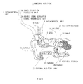
- the reference numeral 1 denotes an embedded audiphone that includes an extracorporeal unit 2 and an intracorporeal unit 3.
- the extracorporeal unit 2 is embedded in a skull 5 that is covered with scalp 4.
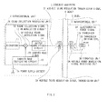
- the extracorporeal unit 2 includes an audible sound modulation signal transmission unit 2A, which is placed on the scalp 4 so as to face the intracorporeal unit 3; and a sound collection processing unit 2B, which supplies an audible sound modulation transmission signal S1 to the audible sound modulation signal transmission unit 2A.
- the sound collection processing unit 2B inputs a sound collection signal S2 obtained by a microphone 11 into an AM modulation circuit 12 where a carrier wave signal S3 supplied from a carrier wave oscillating circuit 13 is amplitude-modulated (AM-modulated) with the use of the sound collection signal S2. In this manner, an audible sound modulation signal S4 is generated.
- the audible sound modulation signal S4 is amplified by an output amplifying circuit 14 and then fed to the audible sound modulation signal transmission unit 2A as the audible sound modulation transmission signal S1.
- the sound collection processing unit 2B is driven by a power supply battery 15 and operates.
- the intracorporeal unit 3 ( FIG. 1 ) is embedded in a portion (the temporal bone under the skin of the mastoid portion, for example) adjacent to the auricle 21 of a user wearing the audiphone. Therefore, the microphone 11 of the sound collection processing unit 2B, which makes up the extracorporeal unit 2 that is so positioned as to face the intracorporeal unit 3, is able to collect audible sound, which the user wearing the embedded audiphone 1 can hear under normal circumstances as the sound reaches an eardrum 23 through an external auditory canal 22.
- the vibrations of the eardrum 23 are passed on to vestibule/cochlea 28 through auditory ossicles 27 including a malleus 24, an incus 25 and a stapes 26. Therefore, sound information is transmitted from the cochlea to a brain stem.
- the embedded audiphone 1 supplies the audible sound modulation transmission signal S1 to an audible sound modulation signal receiving unit 3A of the intracorporeal unit 3 embedded in the skull 5 from the extracorporeal unit 2, thereby creating audible sound vibrations in the intracorporeal unit 3 and conveying the audible sound vibrations to the auditory ossicles 27 through the skull 5.
- the audible sound modulation signal transmission unit 2A of the extracorporeal unit 2 includes an extracorporeal transmitter coil 31 as shown in FIG. 3 , which serves as a means for transmitting the audible sound modulation transmission signal S1 through the scalp 4 to the audible sound modulation signal receiving unit 3A of the intracorporeal unit 3.
- an intracorporeal receiver coil 32 which makes up the audible sound modulation signal receiving unit 3A, is so provided as to face the extracorporeal transmitter coil 31 across the scalp 4. Therefore, a transmission magnetic flux 33, which emerges as the audible sound modulation transmission signal S1 flows through the extracorporeal transmitter coil 31, is interlinked with the intracorporeal receiver coil 32 through the scalp 4. Thus, an electromotive force signal S11 is generated across both end terminals 32A and 32B of the intracorporeal receiver coil 32.
- the electromotive force signal S11 which emerges on the intracorporeal receiver coil 32, is in the same modulation signal format as the audible sound modulation signal S4 ( FIG. 2 ) that the AM modulation circuit 12 obtains. Therefore, a signal containing audible sound information is conveyed from the extracorporeal unit 2 to the intracorporeal unit 3; the electromotive force signal S11 that is obtained across the both end terminals 32A and 32B of intracorporeal receiver coil 32 is fed to a vibration unit 3B, which makes up the intracorporeal unit 3.
- the vibration unit 3B includes a rod-shaped transducer 34 and a transducer driving coil 35, which is wound around the transducer 34.
- the supply of the electromotive force signal S11 to the transducer driving coil 35 generates a magnetic flux, which passes through in a length direction of the rod-shaped transducer 34.
- the transducer 34 is made of a giant magnetostrictive material: the length of the transducer varies according to the amount of the magnetic flux as the magnetic flux passes through in the length direction. Therefore, the length of the rod-shaped transducer 34 varies according to the electromotive force signal S11.
- the electromotive force signal S11 changes in the same signal format as the audible sound modulation signal S4 obtained from the AM modulation circuit 12. Therefore, in response to the sound collection signal S2, which is a result of sound collection by the microphone 11, the length of the transducer 34 vibrates in a direction indicated by arrow a. The vibrations are then fed to the skull 5 as an output of the embedded audiphone 1.
- the intracorporeal unit 3 supplies the vibrations associated with the collected audible sound to the skull 5.
- the vibrations are conveyed to the auditory ossicles 27 via the skull 5 and transmitted as sound information from the vestibule/cochlea 28 to the brain stem.
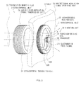
- FIG. 4 shows an example of the above embodiment; the corresponding portions are represented by the same reference symbols.
- the audible sound modulation signal transmission unit 2A of the extracorporeal unit 2 includes a magnetic yoke 41, whose longitudinal cross-sectional surface is in the shape of "E" and which externally looks like a circular cylinder as a whole.
- the extracorporeal transmitter coil 31 is wound around a cylindrical center yoke unit 41A of the magnetic yoke 41.
- a magnetic path is formed from the center yoke unit 41A through a disc-shaped end plate yoke unit 41B so as to pass through a cylindrical yoke unit 41C, which is in the shape of a cylinder.
- the top surfaces of the center yoke unit 41A and cylindrical yoke unit 41C of the magnetic yoke 41 are disposed on the scalp 4.
- the intracorporeal unit 3 includes a magnetic yoke 42, whose longitudinal cross-sectional surface is in the shape of "E" and which externally looks like a circular cylinder: the magnetic yoke 42 faces the magnetic yoke 41.
- the intracorporeal receiver coil 32 is wound around a cylindrical center yoke unit 42A of the magnetic yoke 42.
- the magnetic path allows the transmission magnetic flux 33 to flow to the magnetic yoke 41 of the extracorporeal unit 2 through a disc-shaped end plate yoke unit 42B and a cylindrical yoke unit 42C.
- the transmission magnetic flux 33 which is generated on the cylindrical center yoke unit 41A of the magnetic yoke 41 by the extracorporeal transmitter coil 31 of the extracorporeal unit 2, passes through the scalp 4 as well as the magnetic path from the center yoke unit 42A of the magnetic yoke 42 of the intracorporeal unit 3 through the end plate yoke unit 42B to the cylindrical yoke unit 42C; the transmission magnetic flux 33 further passes through the scalp 4 and then flows through the magnetic path from the cylindrical yoke unit 41C of the magnetic yoke 41 of the extracorporeal unit 2 through the end plate yoke unit 41B to the center yoke unit 41A.
- the transmission magnetic flux 33 generated on the magnetic yoke 41 of the extracorporeal unit 2 passes through the scalp 4 and is interlinked with the intracorporeal receiver coil 32, thereby generating an induced electromotive force.
- a disc-shaped vibration unit mount 47 is so formed as to project outward.
- the vibration unit 3B is bonded to the vibration unit mount 47 so as to project outward.
- the vibration unit 3B includes the transducer 34, whose cross-sectional surface is in the shape of a circle and which is made of a rod-shaped giant magnetostrictive element.
- the transducer driving coil 35 is wound around the transducer 34; both end terminals T1 and T2 of the intracorporeal receiver coil 32 are connected directly to both end terminals T11 and T12 of the transducer driving coil 35.
- an excitation current which corresponds to the audible sound modulation transmission signal S1 that is obtained after the intracorporeal receiver coil 32 is interlinked with the transmission magnetic flux 33, flows through the transducer driving coil 35.
- the transducer 34 expands and contracts because of the elastic properties of the giant magnetostrictive element as illustrated in FIG. 8 , thereby making a tip (where a free end is formed as the other end is fixed to the magnetic yoke 42) of the transducer 34 vibrate.
- the giant magnetostrictive element of which the transducer 34 is made, has the following characteristic: As shown in FIG. 8 , where changes in the amount of expansion and contraction are represented by an elastic characteristic curve K1, as an excitation magnetic field H expands, the giant magnetostrictive element expands much more in response to the excitation magnetic field H.
- a pair of the operating point setup units 48A and 48B which are made of a permanent magnet, is used at both ends of the transducer 34 made of the giant magnetostrictive element. Accordingly, a bias magnetic field H0 is fed to the giant magnetostrictive element. Therefore, when the electromotive force signal S11 is supplied with an excitation operating point HX, which is determined by the bias magnetic field H0, serving as the center, the expansion-and-contraction amount D1 of the transducer 34 changes around an expansion-and-contraction operating point DX, which corresponds to the excitation operating point HX.
- the tip position of the transducer 34 varies according to a change in the expansion-and-contraction amount D1. Therefore, the tip portion of the transducer 34 vibrates.
- the magnetic yoke 42 of the intracorporeal receiver coil 32 is fixed to the skull 5 with fixing screws 45.
- a dome-shaped contact 50 made of a titanium material is provided at the tip of the transducer 34; an outer surface of the contact 50 is in contact with the skull 5. Therefore, a change at the tip of the transducer 34 is conveyed as vibration to the skull 5 via the contact 50.
- a titanium material is used for the contact 50. Therefore, because of the properties of the titanium material, the contact 50 is well adhered to the skull. Moreover, it is possible to make effective use of the advantage that the titanium material is excellent in conveying vibration and easy to process.
- the contact 50 is connected to the end plate yoke unit 42B of the magnetic yoke 42 with a connection ring 51, which is made of a flexible material in the shape of a ring. Therefore, the contact 50 is supported in such a way that the contact 50 is able to vibrate.
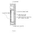
- the sound collection processing unit 2B includes, as shown in FIG. 9 , a sound collection processing board 52, on which the AM modulation circuit 12, the carrier wave oscillating circuit 13 and the output amplifying circuit 14 are mounted as circuitry elements of the sound collection processing unit 2B, inside a sound collection processing unit storage enclosure 60 bonded to the end plate yoke unit 41B of the magnetic yoke 41 that makes up the audible sound modulation signal transmission unit 2A.
- the microphone 11 and the power supply battery 15, which is stored in a battery storage room 53 are placed on the sound collection processing board 52.
- the power supply battery 15 stored in the battery storage room 53 can be replaced with another directly by a user (without the need for a surgical operation) when necessary since a battery cover 54 can be freely opened and closed.
- the intracorporeal unit 3 in a surgical operation for embedding the intracorporeal unit 3, is embedded in the temporal bone under the skin of the mastoid portion in the vicinity of the auricle of the skull 5; and fixed to the skull 5 with fixing screws 45.
- the user Before the intracorporeal unit 3 is used as the embedded audiphone 1, the user sets the extracorporeal unit 2 at the position that faces the intracorporeal unit 3 on the scalp 4.
- the transmission magnetic flux 33 generated by the extracorporeal transmitter coil 31 of the magnetic yoke 41 which makes up the audible sound modulation signal transmission unit 2A of the extracorporeal unit 2, passes through the scalp 4 to form a magnetic path between the magnetic yoke 41 and the magnetic yoke 42 of the intracorporeal unit 3 for transmitting audible sound information.
- a magnetic flux of the permanent magnet which is used to set an operating point of the transducer 34, flows in such a way that the magnetic flux is superimposed.
- the magnetic flux causes an attracting magnetic force that attracts the extracorporeal unit 2 to the intracorporeal unit 3. Therefore, the extracorporeal unit 2 is mounted on the scalp 4 in a stable manner.
- the carrier wave oscillating circuit 13 supplies a pulse signal with a frequency of 40 kHz to the AM modulation circuit 12 as a carrier wave signal S3.
- the audible sound modulation signal S4 a signal that has been amplitude-modulated by the sound collection signal S2 collected by the microphone 11.
- the audible sound modulation signal S4 as an energy source to make the transducer 34 of the intracorporeal unit 3 vibrate, is converted to the transmission magnetic flux 33 by the extracorporeal transmitter coil 31; the transmission magnetic flux 33 is interlinked with the intracorporeal receiver coil 32 of the intracorporeal unit 3, thereby generating an induced electromotive force on the intracorporeal receiver coil 32.
- the induced electromotive force signal S11 is fed to both ends of the transducer driving coil 35 that makes up the vibration unit 3B. As a result, the transducer 34 vibrates.
- the transducer 34 is made of a giant magnetostrictive element having the elastic properties as shown in FIG. 8 . Therefore, thanks to a self-demodulation function obtained from the vibration characteristics of the giant magnetostrictive element, based on the electromotive force signal S11 that is in an AM demodulation format of the pulse carrier wave, a vibration operation takes place in such a way that the expansion-and-contraction amount D1 changes according to the sound collection signal S2, which is an amplitude-modulated component thereof.
- the transducer 34 vibrates in response to the sound collection signal 2, which is an amplitude-modulated component for the carrier-wave pulse signal, the audible sound vibrations are supplied to the skull 5 via the contact 50 and conveyed to the auditory ossicles 27 through the skull 54.
- the giant magnetostrictive element which has the elastic properties as shown in FIG. 8 , is used as the transducer 34 of the intracorporeal unit 3. Therefore, with the use of the self-demodulation function of the giant magnetostrictive element, it is possible to conduct audible sound vibrations clearly through bone to the vestibule/cochlea 28 with no specific AM demodulation circuit provided.
- a displacement measurement device detects the following signals: an fixed end-side displacement detection signal S21, which represents a change of a bonded surface between the operating point setup unit 48A of the transducer 34 and the vibration unit mount 47; and a free end-side displacement detection signal S22, which represents a change of an apical surface of the transducer 34.
- both signals were detected as being in phase. Therefore, it was confirmed that vibrations occurred in the length direction of the transducer 34 made of a rod-shaped giant magnetostrictive element.
- a transducer unit 61 which was made up of the transducer 34 and a pair of the operating point setup units 48A and 48B provided at both ends of the transducer 34, carried out self-demodulation on the audible sound modulation transmission signal, which was in the format of the signal amplitude-modulated by the pulse carrier wave, and output the expansion-and-contraction amount corresponding to the sound collection signal as the expansion-and-contraction amount D1 of the transducer 34 after the electromotive force signal S11, which was in the format of the signal that was generated after the pulse carrier wave was amplitude-modulated by the audible sound signal, was fed to the transducer driving coil 35 as a vibration driving source.
- the present invention can be used for an audiphone.
Landscapes
- Health & Medical Sciences (AREA)
- General Health & Medical Sciences (AREA)
- Otolaryngology (AREA)
- Neurosurgery (AREA)
- Physics & Mathematics (AREA)
- Engineering & Computer Science (AREA)
- Acoustics & Sound (AREA)
- Signal Processing (AREA)
- Circuit For Audible Band Transducer (AREA)
- Prostheses (AREA)
- Magnetic Resonance Imaging Apparatus (AREA)
Applications Claiming Priority (2)
| Application Number | Priority Date | Filing Date | Title |
|---|---|---|---|
| JP2008246342A JP5219037B2 (ja) | 2008-09-25 | 2008-09-25 | 埋込み型骨導補聴器 |
| PCT/JP2009/066709 WO2010035812A1 (ja) | 2008-09-25 | 2009-09-16 | 埋込み型骨導補聴器 |
Publications (3)
| Publication Number | Publication Date |
|---|---|
| EP2329802A1 true EP2329802A1 (de) | 2011-06-08 |
| EP2329802A4 EP2329802A4 (de) | 2014-07-23 |
| EP2329802B1 EP2329802B1 (de) | 2016-06-29 |
Family
ID=42059807
Family Applications (1)
| Application Number | Title | Priority Date | Filing Date |
|---|---|---|---|
| EP09816226.6A Active EP2329802B1 (de) | 2008-09-25 | 2009-09-16 | Eingebettetes audiophon |
Country Status (4)
| Country | Link |
|---|---|
| US (1) | US8520867B2 (de) |
| EP (1) | EP2329802B1 (de) |
| JP (1) | JP5219037B2 (de) |
| WO (1) | WO2010035812A1 (de) |
Families Citing this family (25)
| Publication number | Priority date | Publication date | Assignee | Title |
|---|---|---|---|---|
| JP4593677B2 (ja) | 2007-12-21 | 2010-12-08 | 富士通株式会社 | クロック乗せ換え装置及びクロック乗せ換え方法 |
| US11399234B2 (en) | 2011-12-23 | 2022-07-26 | Shenzhen Shokz Co., Ltd. | Bone conduction speaker and compound vibration device thereof |
| US11611834B2 (en) | 2011-12-23 | 2023-03-21 | Shenzhen Shokz Co., Ltd. | Bone conduction speaker and compound vibration device thereof |
| US8903309B2 (en) * | 2012-06-05 | 2014-12-02 | J.A. Wells and Associates, L.L.C. | True stereo wireless headset and method |
| US20140179985A1 (en) | 2012-12-21 | 2014-06-26 | Marcus ANDERSSON | Prosthesis adapter |
| JP6151570B2 (ja) | 2013-05-29 | 2017-06-21 | 株式会社大野興業 | 手術冶具及び確認冶具並びにこれらの冶具を製造する方法 |
| US10757516B2 (en) | 2013-10-29 | 2020-08-25 | Cochlear Limited | Electromagnetic transducer with specific interface geometries |
| US12483842B2 (en) | 2014-01-06 | 2025-11-25 | Shenzhen Shokz Co., Ltd. | Systems and methods for suppressing sound leakage |
| US12413915B2 (en) | 2014-01-06 | 2025-09-09 | Shenzhen Shokz Co., Ltd. | Systems and methods for suppressing sound leakage |
| US11363392B2 (en) | 2014-01-06 | 2022-06-14 | Shenzhen Shokz Co., Ltd. | Systems and methods for suppressing sound leakage |
| US12464299B2 (en) | 2014-01-06 | 2025-11-04 | Shenzhen Shokz Co., Ltd. | Systems and methods for suppressing sound leakage |
| US12532132B2 (en) | 2014-01-06 | 2026-01-20 | Shenzhen Shokz Co., Ltd. | Systems and methods for suppressing sound leakage |
| CN104093111A (zh) * | 2014-03-25 | 2014-10-08 | 嘉兴益尔电子科技有限公司 | 一种带有汉语音调增强方法的数字助听器 |
| US9800982B2 (en) | 2014-06-18 | 2017-10-24 | Cochlear Limited | Electromagnetic transducer with expanded magnetic flux functionality |
| US10091594B2 (en) | 2014-07-29 | 2018-10-02 | Cochlear Limited | Bone conduction magnetic retention system |
| US10130807B2 (en) | 2015-06-12 | 2018-11-20 | Cochlear Limited | Magnet management MRI compatibility |
| US20160381473A1 (en) | 2015-06-26 | 2016-12-29 | Johan Gustafsson | Magnetic retention device |
| WO2016207856A1 (en) * | 2015-06-26 | 2016-12-29 | Cochlear Limited | Magnetic retention device |
| US10609496B2 (en) * | 2015-08-13 | 2020-03-31 | Shenzhen Voxtech Co., Ltd. | Systems for bone conduction speaker |
| US10917730B2 (en) | 2015-09-14 | 2021-02-09 | Cochlear Limited | Retention magnet system for medical device |
| US9872115B2 (en) | 2015-09-14 | 2018-01-16 | Cochlear Limited | Retention magnet system for medical device |
| US11595768B2 (en) | 2016-12-02 | 2023-02-28 | Cochlear Limited | Retention force increasing components |
| WO2020129021A1 (en) * | 2018-12-21 | 2020-06-25 | Cochlear Limited | Advanced bone conduction implant |
| US12420101B2 (en) | 2019-09-27 | 2025-09-23 | Cochlear Limited | Multipole magnet for medical implant system |
| KR102242838B1 (ko) * | 2020-06-22 | 2021-04-20 | 최민석 | 음성 전달 제어가 가능한 스마트 마스크 및 이를 이용한 음성 전달 제어 시스템 |
Family Cites Families (12)
| Publication number | Priority date | Publication date | Assignee | Title |
|---|---|---|---|---|
| JPH0763494B2 (ja) * | 1986-05-21 | 1995-07-12 | ゾームド―トリース,インコーポレイティド | 埋め込み可能な電磁中耳骨伝導型補聴器 |
| US4982434A (en) | 1989-05-30 | 1991-01-01 | Center For Innovative Technology | Supersonic bone conduction hearing aid and method |
| US5913815A (en) | 1993-07-01 | 1999-06-22 | Symphonix Devices, Inc. | Bone conducting floating mass transducers |
| US5624376A (en) | 1993-07-01 | 1997-04-29 | Symphonix Devices, Inc. | Implantable and external hearing systems having a floating mass transducer |
| US5554096A (en) * | 1993-07-01 | 1996-09-10 | Symphonix | Implantable electromagnetic hearing transducer |
| JP3497320B2 (ja) * | 1996-03-27 | 2004-02-16 | Tdk株式会社 | 骨導式音声伝達装置 |
| ES2278727T3 (es) | 2000-01-31 | 2007-08-16 | Med-El Elektromedizinische Gerate Gmbh | Sistema de implante coclear parcialmente insertable en el oido externo. |
| JP3548805B2 (ja) * | 2002-07-24 | 2004-07-28 | 東北大学長 | 補聴システム及び補聴方法 |
| JP4587195B2 (ja) | 2003-03-19 | 2010-11-24 | 奈良県 | 補聴器 |
| JP4170143B2 (ja) * | 2003-05-15 | 2008-10-22 | 三井造船システム技研株式会社 | 補聴システム |
| JP2007184722A (ja) | 2006-01-05 | 2007-07-19 | Nagasaki Univ | 骨導補聴器及び骨導スピーカ |
| US8246532B2 (en) | 2006-02-14 | 2012-08-21 | Vibrant Med-El Hearing Technology Gmbh | Bone conductive devices for improving hearing |
-
2008
- 2008-09-25 JP JP2008246342A patent/JP5219037B2/ja active Active
-
2009
- 2009-09-16 US US13/120,813 patent/US8520867B2/en active Active
- 2009-09-16 WO PCT/JP2009/066709 patent/WO2010035812A1/ja not_active Ceased
- 2009-09-16 EP EP09816226.6A patent/EP2329802B1/de active Active
Also Published As
| Publication number | Publication date |
|---|---|
| JP5219037B2 (ja) | 2013-06-26 |
| EP2329802B1 (de) | 2016-06-29 |
| US20110243356A1 (en) | 2011-10-06 |
| JP2010075394A (ja) | 2010-04-08 |
| US8520867B2 (en) | 2013-08-27 |
| WO2010035812A1 (ja) | 2010-04-01 |
| EP2329802A4 (de) | 2014-07-23 |
Similar Documents
| Publication | Publication Date | Title |
|---|---|---|
| EP2329802B1 (de) | Eingebettetes audiophon | |
| US11910165B2 (en) | Removable attachment of a passive transcutaneous bone conduction device with limited skin deformation | |
| US8116494B2 (en) | Method for generating an acoustic signal or for transmitting energy in an auditory canal and corresponding hearing apparatus | |
| US9020173B2 (en) | Method and apparatus for harvesting energy in a hearing assistance device | |
| JP4069294B2 (ja) | イヤフォン、音声伝達装置 | |
| US7471805B2 (en) | Hearing aid mechanism | |
| US6084975A (en) | Promontory transmitting coil and tympanic membrane magnet for hearing devices | |
| EP1972179B1 (de) | Hörgerätesystem | |
| EP0671862A1 (de) | Bifunktionelle Kopfhörereinrichtung | |
| US20110286616A1 (en) | Hearing device with a passive unit seated deep in the auditory canal | |
| US8605924B2 (en) | Hearing apparatus including transponder detection and corresponding control method | |
| CN101895510B (zh) | 用于在助听器之间无线数据传输的装置和方法 | |
| US9179226B2 (en) | Partially implantable hearing device | |
| JP2010118877A (ja) | 体内埋込型スピーカ | |
| JP4863981B2 (ja) | 補聴装置の制御方法 | |
| KR100205517B1 (ko) | 중이 이식형 보청기 | |
| Killion et al. | Hearing aid transducers | |
| KR101484730B1 (ko) | 골 전도 디바이스 및 그를 이용한 헤드셋 | |
| JP2012054430A (ja) | 骨振動装置 | |
| Zurcher et al. | Effect of incus removal on middle ear acoustic sensor for a fully implantable cochlear prosthesis | |
| JP2023072616A (ja) | 骨伝導を利用した聴音装置 | |
| JP2004140719A (ja) | 骨伝導発生装置 | |
| CN118433621A (zh) | 用于运行听力设备的方法 | |
| JP2007251643A (ja) | 音伝達システム |
Legal Events
| Date | Code | Title | Description |
|---|---|---|---|
| PUAI | Public reference made under article 153(3) epc to a published international application that has entered the european phase |
Free format text: ORIGINAL CODE: 0009012 |
|
| 17P | Request for examination filed |
Effective date: 20110323 |
|
| AK | Designated contracting states |
Kind code of ref document: A1 Designated state(s): AT BE BG CH CY CZ DE DK EE ES FI FR GB GR HR HU IE IS IT LI LT LU LV MC MK MT NL NO PL PT RO SE SI SK SM TR |
|
| AX | Request for extension of the european patent |
Extension state: AL BA RS |
|
| DAX | Request for extension of the european patent (deleted) | ||
| A4 | Supplementary search report drawn up and despatched |
Effective date: 20140620 |
|
| RIC1 | Information provided on ipc code assigned before grant |
Ipc: H04R 15/00 20060101ALI20140613BHEP Ipc: A61F 11/00 20060101AFI20140613BHEP Ipc: H04R 25/00 20060101ALI20140613BHEP |
|
| GRAP | Despatch of communication of intention to grant a patent |
Free format text: ORIGINAL CODE: EPIDOSNIGR1 |
|
| INTG | Intention to grant announced |
Effective date: 20160212 |
|
| RIN1 | Information on inventor provided before grant (corrected) |
Inventor name: HATO, NAOHITO Inventor name: YAMAMOTO, KENSEI Inventor name: KOIKE, TAKUJI |
|
| GRAS | Grant fee paid |
Free format text: ORIGINAL CODE: EPIDOSNIGR3 |
|
| GRAA | (expected) grant |
Free format text: ORIGINAL CODE: 0009210 |
|
| AK | Designated contracting states |
Kind code of ref document: B1 Designated state(s): AT BE BG CH CY CZ DE DK EE ES FI FR GB GR HR HU IE IS IT LI LT LU LV MC MK MT NL NO PL PT RO SE SI SK SM TR |
|
| REG | Reference to a national code |
Ref country code: GB Ref legal event code: FG4D |
|
| REG | Reference to a national code |
Ref country code: CH Ref legal event code: EP |
|
| REG | Reference to a national code |
Ref country code: AT Ref legal event code: REF Ref document number: 808495 Country of ref document: AT Kind code of ref document: T Effective date: 20160715 |
|
| REG | Reference to a national code |
Ref country code: IE Ref legal event code: FG4D |
|
| REG | Reference to a national code |
Ref country code: DE Ref legal event code: R096 Ref document number: 602009039506 Country of ref document: DE |
|
| REG | Reference to a national code |
Ref country code: LT Ref legal event code: MG4D |
|
| PG25 | Lapsed in a contracting state [announced via postgrant information from national office to epo] |
Ref country code: FI Free format text: LAPSE BECAUSE OF FAILURE TO SUBMIT A TRANSLATION OF THE DESCRIPTION OR TO PAY THE FEE WITHIN THE PRESCRIBED TIME-LIMIT Effective date: 20160629 Ref country code: NO Free format text: LAPSE BECAUSE OF FAILURE TO SUBMIT A TRANSLATION OF THE DESCRIPTION OR TO PAY THE FEE WITHIN THE PRESCRIBED TIME-LIMIT Effective date: 20160929 Ref country code: LT Free format text: LAPSE BECAUSE OF FAILURE TO SUBMIT A TRANSLATION OF THE DESCRIPTION OR TO PAY THE FEE WITHIN THE PRESCRIBED TIME-LIMIT Effective date: 20160629 |
|
| REG | Reference to a national code |
Ref country code: NL Ref legal event code: MP Effective date: 20160629 |
|
| PG25 | Lapsed in a contracting state [announced via postgrant information from national office to epo] |
Ref country code: LV Free format text: LAPSE BECAUSE OF FAILURE TO SUBMIT A TRANSLATION OF THE DESCRIPTION OR TO PAY THE FEE WITHIN THE PRESCRIBED TIME-LIMIT Effective date: 20160629 Ref country code: SE Free format text: LAPSE BECAUSE OF FAILURE TO SUBMIT A TRANSLATION OF THE DESCRIPTION OR TO PAY THE FEE WITHIN THE PRESCRIBED TIME-LIMIT Effective date: 20160629 Ref country code: HR Free format text: LAPSE BECAUSE OF FAILURE TO SUBMIT A TRANSLATION OF THE DESCRIPTION OR TO PAY THE FEE WITHIN THE PRESCRIBED TIME-LIMIT Effective date: 20160629 Ref country code: NL Free format text: LAPSE BECAUSE OF FAILURE TO SUBMIT A TRANSLATION OF THE DESCRIPTION OR TO PAY THE FEE WITHIN THE PRESCRIBED TIME-LIMIT Effective date: 20160629 Ref country code: GR Free format text: LAPSE BECAUSE OF FAILURE TO SUBMIT A TRANSLATION OF THE DESCRIPTION OR TO PAY THE FEE WITHIN THE PRESCRIBED TIME-LIMIT Effective date: 20160930 |
|
| PG25 | Lapsed in a contracting state [announced via postgrant information from national office to epo] |
Ref country code: RO Free format text: LAPSE BECAUSE OF FAILURE TO SUBMIT A TRANSLATION OF THE DESCRIPTION OR TO PAY THE FEE WITHIN THE PRESCRIBED TIME-LIMIT Effective date: 20160629 Ref country code: EE Free format text: LAPSE BECAUSE OF FAILURE TO SUBMIT A TRANSLATION OF THE DESCRIPTION OR TO PAY THE FEE WITHIN THE PRESCRIBED TIME-LIMIT Effective date: 20160629 Ref country code: CZ Free format text: LAPSE BECAUSE OF FAILURE TO SUBMIT A TRANSLATION OF THE DESCRIPTION OR TO PAY THE FEE WITHIN THE PRESCRIBED TIME-LIMIT Effective date: 20160629 Ref country code: IT Free format text: LAPSE BECAUSE OF FAILURE TO SUBMIT A TRANSLATION OF THE DESCRIPTION OR TO PAY THE FEE WITHIN THE PRESCRIBED TIME-LIMIT Effective date: 20160629 Ref country code: IS Free format text: LAPSE BECAUSE OF FAILURE TO SUBMIT A TRANSLATION OF THE DESCRIPTION OR TO PAY THE FEE WITHIN THE PRESCRIBED TIME-LIMIT Effective date: 20161029 Ref country code: SK Free format text: LAPSE BECAUSE OF FAILURE TO SUBMIT A TRANSLATION OF THE DESCRIPTION OR TO PAY THE FEE WITHIN THE PRESCRIBED TIME-LIMIT Effective date: 20160629 |
|
| PG25 | Lapsed in a contracting state [announced via postgrant information from national office to epo] |
Ref country code: BE Free format text: LAPSE BECAUSE OF NON-PAYMENT OF DUE FEES Effective date: 20160629 Ref country code: ES Free format text: LAPSE BECAUSE OF FAILURE TO SUBMIT A TRANSLATION OF THE DESCRIPTION OR TO PAY THE FEE WITHIN THE PRESCRIBED TIME-LIMIT Effective date: 20160629 Ref country code: SM Free format text: LAPSE BECAUSE OF FAILURE TO SUBMIT A TRANSLATION OF THE DESCRIPTION OR TO PAY THE FEE WITHIN THE PRESCRIBED TIME-LIMIT Effective date: 20160629 Ref country code: PL Free format text: LAPSE BECAUSE OF FAILURE TO SUBMIT A TRANSLATION OF THE DESCRIPTION OR TO PAY THE FEE WITHIN THE PRESCRIBED TIME-LIMIT Effective date: 20160629 Ref country code: PT Free format text: LAPSE BECAUSE OF FAILURE TO SUBMIT A TRANSLATION OF THE DESCRIPTION OR TO PAY THE FEE WITHIN THE PRESCRIBED TIME-LIMIT Effective date: 20161031 |
|
| REG | Reference to a national code |
Ref country code: DE Ref legal event code: R097 Ref document number: 602009039506 Country of ref document: DE |
|
| PG25 | Lapsed in a contracting state [announced via postgrant information from national office to epo] |
Ref country code: MC Free format text: LAPSE BECAUSE OF FAILURE TO SUBMIT A TRANSLATION OF THE DESCRIPTION OR TO PAY THE FEE WITHIN THE PRESCRIBED TIME-LIMIT Effective date: 20160629 |
|
| REG | Reference to a national code |
Ref country code: CH Ref legal event code: PL |
|
| PLBE | No opposition filed within time limit |
Free format text: ORIGINAL CODE: 0009261 |
|
| STAA | Information on the status of an ep patent application or granted ep patent |
Free format text: STATUS: NO OPPOSITION FILED WITHIN TIME LIMIT |
|
| GBPC | Gb: european patent ceased through non-payment of renewal fee |
Effective date: 20160929 |
|
| PG25 | Lapsed in a contracting state [announced via postgrant information from national office to epo] |
Ref country code: DK Free format text: LAPSE BECAUSE OF FAILURE TO SUBMIT A TRANSLATION OF THE DESCRIPTION OR TO PAY THE FEE WITHIN THE PRESCRIBED TIME-LIMIT Effective date: 20160629 |
|
| 26N | No opposition filed |
Effective date: 20170330 |
|
| REG | Reference to a national code |
Ref country code: IE Ref legal event code: MM4A |
|
| REG | Reference to a national code |
Ref country code: FR Ref legal event code: ST Effective date: 20170531 |
|
| PG25 | Lapsed in a contracting state [announced via postgrant information from national office to epo] |
Ref country code: FR Free format text: LAPSE BECAUSE OF NON-PAYMENT OF DUE FEES Effective date: 20160930 Ref country code: IE Free format text: LAPSE BECAUSE OF NON-PAYMENT OF DUE FEES Effective date: 20160916 Ref country code: LI Free format text: LAPSE BECAUSE OF NON-PAYMENT OF DUE FEES Effective date: 20160930 Ref country code: GB Free format text: LAPSE BECAUSE OF NON-PAYMENT OF DUE FEES Effective date: 20160929 Ref country code: CH Free format text: LAPSE BECAUSE OF NON-PAYMENT OF DUE FEES Effective date: 20160930 |
|
| PG25 | Lapsed in a contracting state [announced via postgrant information from national office to epo] |
Ref country code: SI Free format text: LAPSE BECAUSE OF FAILURE TO SUBMIT A TRANSLATION OF THE DESCRIPTION OR TO PAY THE FEE WITHIN THE PRESCRIBED TIME-LIMIT Effective date: 20160629 Ref country code: BG Free format text: LAPSE BECAUSE OF FAILURE TO SUBMIT A TRANSLATION OF THE DESCRIPTION OR TO PAY THE FEE WITHIN THE PRESCRIBED TIME-LIMIT Effective date: 20160929 Ref country code: LU Free format text: LAPSE BECAUSE OF NON-PAYMENT OF DUE FEES Effective date: 20160916 |
|
| PG25 | Lapsed in a contracting state [announced via postgrant information from national office to epo] |
Ref country code: HU Free format text: LAPSE BECAUSE OF FAILURE TO SUBMIT A TRANSLATION OF THE DESCRIPTION OR TO PAY THE FEE WITHIN THE PRESCRIBED TIME-LIMIT; INVALID AB INITIO Effective date: 20090916 Ref country code: CY Free format text: LAPSE BECAUSE OF FAILURE TO SUBMIT A TRANSLATION OF THE DESCRIPTION OR TO PAY THE FEE WITHIN THE PRESCRIBED TIME-LIMIT Effective date: 20160629 |
|
| PG25 | Lapsed in a contracting state [announced via postgrant information from national office to epo] |
Ref country code: MT Free format text: LAPSE BECAUSE OF NON-PAYMENT OF DUE FEES Effective date: 20160930 Ref country code: MK Free format text: LAPSE BECAUSE OF FAILURE TO SUBMIT A TRANSLATION OF THE DESCRIPTION OR TO PAY THE FEE WITHIN THE PRESCRIBED TIME-LIMIT Effective date: 20160629 Ref country code: TR Free format text: LAPSE BECAUSE OF FAILURE TO SUBMIT A TRANSLATION OF THE DESCRIPTION OR TO PAY THE FEE WITHIN THE PRESCRIBED TIME-LIMIT Effective date: 20160629 |
|
| REG | Reference to a national code |
Ref country code: AT Ref legal event code: UEP Ref document number: 808495 Country of ref document: AT Kind code of ref document: T Effective date: 20160629 |
|
| P01 | Opt-out of the competence of the unified patent court (upc) registered |
Effective date: 20230525 |
|
| PGFP | Annual fee paid to national office [announced via postgrant information from national office to epo] |
Ref country code: DE Payment date: 20250722 Year of fee payment: 17 |
|
| PGFP | Annual fee paid to national office [announced via postgrant information from national office to epo] |
Ref country code: AT Payment date: 20250827 Year of fee payment: 17 |