EP2329864A2 - Fixation de ski dotée d'une structure en cage - Google Patents
Fixation de ski dotée d'une structure en cage Download PDFInfo
- Publication number
- EP2329864A2 EP2329864A2 EP10182159A EP10182159A EP2329864A2 EP 2329864 A2 EP2329864 A2 EP 2329864A2 EP 10182159 A EP10182159 A EP 10182159A EP 10182159 A EP10182159 A EP 10182159A EP 2329864 A2 EP2329864 A2 EP 2329864A2
- Authority
- EP
- European Patent Office
- Prior art keywords
- binding
- skeleton
- joint
- spring
- housing
- Prior art date
- Legal status (The legal status is an assumption and is not a legal conclusion. Google has not performed a legal analysis and makes no representation as to the accuracy of the status listed.)
- Granted
Links
Images



Classifications
-
- A—HUMAN NECESSITIES
- A63—SPORTS; GAMES; AMUSEMENTS
- A63C—SKATES; SKIS; ROLLER SKATES; DESIGN OR LAYOUT OF COURTS, RINKS OR THE LIKE
- A63C9/00—Ski bindings
- A63C9/08—Ski bindings yieldable or self-releasing in the event of an accident, i.e. safety bindings
- A63C9/0807—Ski bindings yieldable or self-releasing in the event of an accident, i.e. safety bindings for both towing and downhill skiing
-
- A—HUMAN NECESSITIES
- A63—SPORTS; GAMES; AMUSEMENTS
- A63C—SKATES; SKIS; ROLLER SKATES; DESIGN OR LAYOUT OF COURTS, RINKS OR THE LIKE
- A63C9/00—Ski bindings
- A63C9/08—Ski bindings yieldable or self-releasing in the event of an accident, i.e. safety bindings
- A63C9/084—Ski bindings yieldable or self-releasing in the event of an accident, i.e. safety bindings with heel hold-downs, e.g. swingable
- A63C9/0844—Ski bindings yieldable or self-releasing in the event of an accident, i.e. safety bindings with heel hold-downs, e.g. swingable the body pivoting about a transverse axis
-
- A—HUMAN NECESSITIES
- A63—SPORTS; GAMES; AMUSEMENTS
- A63C—SKATES; SKIS; ROLLER SKATES; DESIGN OR LAYOUT OF COURTS, RINKS OR THE LIKE
- A63C9/00—Ski bindings
- A63C9/08—Ski bindings yieldable or self-releasing in the event of an accident, i.e. safety bindings
- A63C9/084—Ski bindings yieldable or self-releasing in the event of an accident, i.e. safety bindings with heel hold-downs, e.g. swingable
- A63C9/0846—Details of the release or step-in mechanism
-
- A—HUMAN NECESSITIES
- A63—SPORTS; GAMES; AMUSEMENTS
- A63C—SKATES; SKIS; ROLLER SKATES; DESIGN OR LAYOUT OF COURTS, RINKS OR THE LIKE
- A63C9/00—Ski bindings
- A63C9/08—Ski bindings yieldable or self-releasing in the event of an accident, i.e. safety bindings
- A63C9/084—Ski bindings yieldable or self-releasing in the event of an accident, i.e. safety bindings with heel hold-downs, e.g. swingable
- A63C9/0848—Structure or making
-
- A—HUMAN NECESSITIES
- A63—SPORTS; GAMES; AMUSEMENTS
- A63C—SKATES; SKIS; ROLLER SKATES; DESIGN OR LAYOUT OF COURTS, RINKS OR THE LIKE
- A63C9/00—Ski bindings
- A63C9/08—Ski bindings yieldable or self-releasing in the event of an accident, i.e. safety bindings
- A63C9/085—Ski bindings yieldable or self-releasing in the event of an accident, i.e. safety bindings with sole hold-downs, e.g. swingable
- A63C9/08592—Structure or making
Definitions
- the invention relates to a ski binding with reduced weight.
- a feature of skis is their weight. For touring skis the lowest possible weight has always been required. But should also be the usual pistes ski, not least in terms of manageability in the unbent state.
- the demand for light weight can be met by using lightweight materials, composite structures and the like. Limits are set to these aspirations by the availability of appropriate materials and the price. In view of the already achieved degree of perfecting the skis and bindings on the one hand and the often extreme loads, the high functionality and safety requirements on the other hand, further weight reductions are difficult to achieve.
- the invention is based on a ski binding which comprises a ski structure connected or connectable with a ski, a sole holder, a joint movably connecting the sole holder to the bearing structure, and a spring member against the spring force of which the sole holder in the joint is movable relative to the bearing structure.
- the bearing structure is part of a front part or heel part of the binding.
- the invention relates according to ski bindings with front part and heel part, as well as such ski bindings only the front part or only the heel part.
- the invention relates to the ski binding as such, still detached from the ski, as well as in the connected, mounted on the ski state.
- the bearing structure is correspondingly already connected to the ski or, as far as the binding is only as such, with a ski yet connectable.
- the bearing structure fulfills at least the functions of the connection to the ski, either directly or only via a further bearing structure, and the movable mounting of the sole holder. It may either be formed in one piece or composed of a plurality of separately manufactured parts, wherein the parts in the assembled state relative to each other are preferably not movable, ie relative to each other can not perform required for the function of the binding movements.
- the hinge is formed by a first hinge element of the bearing structure and a second hinge element of the sole holder.
- the second joint member is preferably fixedly connected to the sole holder, so not movable relative to the sole holder.
- the first joint element is firmly connected to the bearing structure, relative to this so not movable.
- the spring member is supported on a firmly connected to the sole holder, relative to the sole holder not movable spring support.
- the spring member may be supported directly on this spring support or, more preferably, indirectly via a spring member seat member, which in turn is indirectly or directly supported on the spring support fixedly connected to the sole holder.
- the spring force of the spring member is transmitted via the spring support on the sole holder, and conversely, forces exerted on the sole holder forces act on the spring support on the spring member.
- a binding frame of the heel part or the front part of the binding forming the sole holder, the second joint element and the spring support as a unit is a skeleton.
- the word “or” is always understood by the invention in the usual logical sense of an “inclusive or”, thus includes the meaning of “either ... or” and also the meaning of "and”, as far as the respective concrete context only one of these two meanings can result alone.
- a binding housing of the front part or only a binding housing of the heel part is a skeleton or, particularly preferably, both a binding housing of the front part and a binding housing of the heel part each are a skeleton.
- the binding housing is under the action of an external force on which the binding is designed in a force flow extending from the sole holder via the second joint element to the spring support, ie in the force flow from the second joint element to the sole holder and also in the force flow from the second joint element to the spring support, a skeleton.
- the skeleton can also be regarded as a framework, preferably it is a three-dimensional framework.
- the truss can have one or more curvatures, including curvatures about axes which are not parallel to one another, that is to say they are curved multidimensionally.
- the binding housing forms a skeleton in that it is reduced within said power flow on force or torque transmitting, interconnected ribbed webs.
- the footbridges of the Gerippes are spaced apart, so that remain free spaces between the webs.
- the ribbed webs are interconnected only in skeleton nodes so that they can absorb the occurring forces and torques and pass them on within the skeleton.
- the invention reduces the binding housing to its basic function of force and torque transmission and thereby saves material and weight.
- the binding housing of the heel portion may also form a tread pom, upon which the skier steps when buckling the ski as it rises into the binding, thereby closing the binding.
- the binding housing is also a skeleton in the above-mentioned sense in a force flow passing from the tread spur to the second joint element and from this to the spring support.
- the binding housing may have an actuating portion, by the actuation of which the user can open the binding to take off the ski.
- the sole holder, the second hinge element, the spring support and the actuating portion form a moving unit, preferably a unit obtained by a method of forming the original.
- the binding housing is also a skeleton in the operating area.
- the binding housing in preferred embodiments, has a left side rib structure, a right trough side structure spaced therefrom, and at least one tenter cross structure interconnecting the trough side structures.
- the skeleton side structures may advantageously each themselves, as such, be a skeleton.
- each of the skeleton side structures has a circumferential belt which extends at a radial distance around the second joint element formed by the binding housing and connecting webs which connect the circumferential belt to the second joint element are, as it were, supported on the second joint elements.
- the peripheral belt is inherently stiff and is further stiffened by the connecting webs.
- Such a skeleton side structure is similar in geometry and despite different loads also with regard to the internal load distribution of a wheel with spokes, the second joint element replace the hub, the peripheral belt the rim and the connecting webs the spokes of the wheel.
- the skeleton side structures extend at least substantially in the longitudinal direction of the ski and can therefore also be referred to as skeleton longitudinal structures.
- the skeleton side structures may each be shaped in particular in the manner of a truss, preferably as a two-dimensional truss with curvature (s), optionally also as a two-dimensional truss only.
- the skeleton as a whole forms with its at least two, preferably only two skeleton side structures and the at least one skeleton substructure a kind of three-dimensional framework.
- the skeleton structure supports the skeleton side structures transversely to the longitudinal direction against each other. It transmits compressive and tensile forces in the transverse direction.
- the binding housing preferably has a plurality of skeleton transverse structures, each spaced from each other.
- the skeleton is stiff in preferred embodiments.
- the webs and nodes that make up the skeleton are immovable relative to one another, apart from occurring during force or torque transmission elastic deformations.
- the skeleton may in particular be formed in one piece.
- the skeleton is molded in one piece by injection molding of plastic.
- a three-dimensional framework may be formed with one or more cores inserted in the injection mold, with the core (s) being pulled out of the injection molding framework after casting.
- the skeleton can also be composed of several, each separately shaped parts to form a moving unit.
- two skeleton side structures can be molded as a unit in the injection molding of plastic, while a skeleton structure of a plastic or metallic material is formed and joined to the skeleton side structures, preferably at least including a positive connection, for example by means of a connector, optionally supplemented by a detent or a material closure connection.
- the joint preferably comprises a pivot, and more preferably it is a hinge so that the sole holder in the hinge has only a single degree of freedom of movement, rotation.
- the binding housing forms a multi-arm lever with respect to the force or torque transmission with a first lever arm serving as opening lever and a second lever arm forming the sole holder.
- both lever arms are formed as a skeleton.
- the sole holder and the spring support form about the joint a kind of rocker with the sole holder as the one and the spring support as the other end of the rocker.
- the mentioned tread pum present is arranged at the end of a third lever arm of the binding housing, wherein the third lever arm can be expected in the first approximation to the second lever arm, at the end of the sole holder is arranged. Basically, however, it is about different lever arms, one of which assumes the lever function when entering the binding and the other in an emergency when releasing the binding.
- the binding housing is also formed in the region of the third lever arm leading to the tread spur as a skeleton.
- the already mentioned operating range for releasing the binding is part of the opening lever, in whose area advantageously the spring support is arranged.
- the opening lever as a whole, ie in the area between the second joint elements and the spring support and also in the operating region, which is expediently formed by the second joint element from behind the spring support, a skeleton.
- this circumferential belt is advantageously circumferentially closed around the second joint element.
- the Urrzfangsgurt forms in its front region, seen in the direction of travel of the ski in front of the joint advantageously also equal to the sole holder or a part of the sole holder.
- the circumferential belt extends above and below the second joint element in the longitudinal direction to the rear to the spring support and preferably also beyond the spring support further back into the preferably arranged there actuating region.
- the said tread side structures form the second Gelenkegruent.
- the laterally spaced apart skeletal side structures may be interconnected by the second hinge member, the hinge member would extend from one skeletal side structure to the other in such embodiments, and may form the skeletal cross structure or one of a plurality of skeletal cross structures. More preferably, however, one of the skeleton side structures forms a left and the other a right part of the second Gelenkeleznents.
- the said, at least one skeleton transverse structure forms one of the joint elements of the joint.
- the skeletal cross structure may be shaped as a crossbar that clings to the skeleton side structures.
- the cross bar can be formed with a bracket middle section which extends between the skeleton side structures and from this left and right projecting a left and a right bar leg.
- the at least one skeleton transverse structure can be arranged in particular in the region of the sole holder.
- a skeleton structure can also form a middle section of the sole holder, adjoining the outside, left and right, in each case an end section of the sole holder, wherein the end sections are preferably formed on the skeleton side structures.
- the least a skeleton structure can also be formed by the spring support. It is advantageous if in the front region of the binding housing, a first transverse structure is present, which can form in particular a central portion of the sole holder, and at least one further, second skeleton transverse structure forms the spring support.
- a third transverse structure, seen from the second joint element, is still provided behind the spring support, preferably at the rear end of the binding housing.
- the skeleton has a plurality of transverse structures, these are preferably spaced apart from one another at clear distances, so that the binding housing as a whole is obtained as a multiply perforated structure, preferably as a unit, as a one-piece skeleton.
- the webs forming the skeleton fulfill only the function of force or torque transmission and, optionally, one or more of the functions mentioned, such as those of the sole holder and the spring support.
- the binding housing accommodates the spring member in a receiving space and, in spite of its structuring as a skeleton, fulfills a housing function, namely that of a receptacle.
- the spring member is preferably co-movable with the binding housing so as to participate in the movements of the binding housing relative to the bearing structure.
- the spring member acts on an engagement member to clamp this in a guide contact with a guide cam, it performs the engagement member in the direction of the guide curve back and forth, so fulfills a leadership function.
- At least one of the rib webs can form a guide, preferably a sliding guide, directly for the engagement member.
- the binding housing fulfills both functions, the receiving and the guiding function.
- the receiving space preferably has a lateral opening so that it opens across this opening transversely to the direction of the spring force of the spring member.
- the binding housing preferably accommodates in the region of the receiving space not only the spring member but also the engagement member and forms a housing guide in the receiving space, which guides the engagement member in the direction of a guide curve and in the opposite direction to and fro.
- the spring member biases the engagement member into a guiding contact with the guide cam.
- Guide cam and engaging member together form a cam gear.
- the guide cam, the engagement member and the spring member are part of a control mechanism for controlling the opening and closing of the binding.
- the lateral opening is advantageous for the assembly of the binding in that during assembly, the spring member and the engagement member can be inserted through the opening in the transverse direction to the force acting in the mounted state spring force into the receiving space.
- the receiving space is formed in preferred embodiments so that in a preferred method of Urformung, injection molding, in the injection mold, a core can be arranged, but instead can project from a side wall of the injection mold into the interior of the fort instead.
- This core is overmolded so that it protrudes after injection molding in the receiving space thus obtained.
- the core is the negative shape of the recording room. After or as it is removed from the mold, the core is pulled sideways out of the receiving space thus formed, or the binding housing is pulled off the core, whereby the opening is obtained.
- the receiving space is bounded directly by the skeleton side structures on opposite sides.
- the skeleton side structures may form said housing guide or a part of the housing guide on their inner sides.
- the sole holder is rotatably movable in the joint relative to the bearing structure about a rotation axis.
- One of the hinge elements is a socket.
- the other one Articulated elements is a hollow axle or shaft with free internal cross-section located with the bushing in a rotary sliding contact. Even in such an embodiment, it is preferred if the bearing structure and the binding housing each form a socket, one of these sockets is the socket of the joint and the other of these sockets receives the hollow axle or shaft.
- the hollow axle or shaft may have an outer diameter of at least 10 mm, preferably at least 12 mm, at least over the axial length of the rotary sliding contact.
- a diameter of the inner cross section is in preferred embodiments over at least approximately the entire length of the hollow shaft or shaft in each direction radially to the axis of rotation at least three times, preferably at least viennal as large as the local wall thickness of the hollow shaft or shaft.
- a control mechanism that controls the size of the spring force when opening and closing the binding having a guide curve, which is formed directly from the bearing structure.
- a control mechanism that controls the size of the spring force when opening and closing the binding having a guide curve, which is formed directly from the bearing structure.
- the arrangement of the spring member in such a way that a spring axis of action along which the spring force of the spring member acts on the spring support, or one of the spring support in a guide contact of the control mechanism extending axis coincident with the spring axis of action but can not, deviates from a connecting axis extending radially from the spring support on a hinge axis of the joint, the joint axis thus cuts.
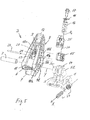
- FIGS. 1 to 4 show a heel part of a ski binding in different views.
- the heel part comprises a bearing structure 1, which can be fastened to a ski, and a binding housing 2, which is connected in a joint with the bearing structure 1 so as to be rotationally movable about a rotation axis Y.
- the bearing structure 1 has a base with a particular in FIG. 4 recognizable fastening device, by means of which it is pushed onto rails arranged on the ski and this is connected behind the ski.
- the bearing structure 1 comprises a first joint element 3 and the binding housing 2 comprises a second joint element 4 of the joint formed by these two joint elements 3 and 4.
- the hinge 3, 4 is a swivel joint.
- the second joint element 4 forms a bushing for the joint element 3.
- the joint 3, 4 is formed in the region of a bearing block 5, which rises from the base of the bearing structure 1.
- the binding housing 2 is multifunctional: it fulfills a holding function by being in one in the FIGS. 1 to 4 a step-in function, which facilitates the buckling of the ski, an opening function in that it is manually operable for unbuckling the ski and thereby movable from the closed position to an open position, and finally, in particular, a trigger function to reduce the risk of injury to the skier.
- a sole holder 6 is formed at a front end of the binding housing 2, which engages behind the sole of the ski boot in the closed position from above and presses the ski boot in the direction of the ski.
- the step-in function is fulfilled by means of a Triitsporns 7, which is also formed at the front end of the binding housing 2 abragend at a distance below the sole holder 6.
- the binding housing 2 is held in the closed position by means of a spring member 16. It is against the spring force of the spring member 16 about the rotation axis Y from the closed position, in FIG. 1 in the clockwise direction, in the open position and from this back to the closed position pivotally.
- the closed position and the open position are stable positions, from which the binding housing 2 can pivot against the spring force in the other of these two positions, such as when triggered, when in the closed position on the sole holder 6, a correspondingly large torque about the rotation axis Y acts ,
- the spring member 16 is supported on the one hand in the region of the bearing block 5 on the bearing structure 1 and on the other hand in a spring support, 9 in the region of the opening lever 8 on the binding housing 2 from.
- the spring support 9 is an integral part of the binding housing 2.
- the spring member 16 is functionally a compression spring, so stretched under pressure, and the shape of a coil spring.
- the spring support 9 is arranged with respect to the longitudinal direction X behind the hinge 3, 4.
- the binding housing 2 is seen in the region of the opening lever 8 from the joint 3, 4 extended beyond the spring support 9 out to the rear and can form an operating area in particular in the extension, for example, by pressure with the ski pole and thereby caused, in the illustration of FIG. 1 counterclockwise pivotal movement of the binding housing 2 to open the binding comfortably and rise from the bond can.
- the binding housing 2 executes the movements required to perform the functions as a unit.
- it is as preferred also formed as a single part, as a unit, but in principle it could instead also be composed of several parts to form a movement unit.
- It forms a lever, which is pivotable about the hinge axis 3, 4 and points perpendicular to the longitudinal direction X.
- the lever is rigid and multi-armed.
- a first arm of the lever projecting from the hinge 3, 4 serves as an opening lever 8.
- a second lever arm protruding forwards from the hinge 3, 4 extends into the sole holder 6.
- the tread spur 7 is formed at the front end of a third lever arm which extends Although it extends close to the second lever arm, but differs from this with respect to the force flow taking place under load.
- the binding housing 2 is a skeleton. It consists in the manner of a three-dimensional framework of spaced apart, only in knots interconnected Gerippestegen together, whose lengths, cross-sectional areas and cross-sectional shapes and orientations are optimized relative to each other with respect to the forces and torques to be transmitted.
- the joint element 3 is shaped as a hollow element and remains free in the assembled, functional state of the heel part inside. It serves as a hollow axle or shaft and has a significantly lower wall thickness in comparison with its inner diameter.
- FIG. 5 shows the heel part in an exploded view.
- the individual components of the heel part are shown relative to each other in positions and orientations suitable for assembly.
- the binding housing 2 is detachable from the other components of the heel part recognizable as a unitary whole.
- From the bearing structure 1 can also be seen the exposed bearing block 5.
- the bearing block 5 is axially interrupted with respect to the axis of rotation Y, so that a left and a right bearing block are present.
- Each of the bearing blocks 5 has an axial passage 13 into which the joint element 3 is inserted during assembly.
- the one bearing block thus forms a right sleeve 51 and the other in the axial alignment a left sleeve 5r for the joint elements.
- the bearing housing 1 and the binding housing 2 are coupled together by means of a control mechanism to which the spring member 16 belongs.
- the control mechanism generates, by means of the spring member 16, a restoring torque that must be overcome in order to move the binding housing 2 from one of its two stable end positions, the closed position and the released or open position, to the other end position.
- the control mechanism comprises a guide cam 14 formed on the bearing structure 1, and an engaging member 15 which is in a guide contact with the guide cam 14 in the assembled condition of the heel member.
- the spring member 16 presses the engaging member 15 in the guide contact.
- the binding housing 2 forms a receiving space for receiving the engaging member 15 and the spring member 16. In this respect, it performs a housing function, namely that of receiving control components of the control mechanism.
- the receiving space has laterally, transversely to a Federwirkachse A 1 , on a side remote from the bearing structure 1 side, in the embodiment as preferred on the top, an opening 20 which serves as assembly opening in the assembly of the heel part by the engaging member 15 and the spring member 16 are inserted through this lateral opening 20 in the receiving space.
- the opening 20 extends to the Spring support 9, which limits the receiving space on its side facing away from the guide cam 14 side.
- the opening 20 extends in the direction of the sole holder 6 to at least the guide curve 14, in the embodiment even a little way beyond the guide curve 20 also.
- the receiving space has due to the formation of the binding housing 2 as skeleton further openings, in particular lateral openings to the left and right, these other, only the GcrippestrulCtur owed openings are not suitable for mounting the engaging member 15 and the spring member 16.
- the shaping of the comparatively large mounting opening 20 and the structuring of the binding housing 2 as a framework come to meet each other, the opening 20 results naturally from the skeleton structure.
- the engagement member 15 is in the assembled state back and forth movable on the spring member 16 on the binding housing 2, namely supported on the spring support 9.
- the binding housing 2 forms in the receiving space for the engaging member 15 a housing guide 21, preferably a linear guide parallel to the spring axis A 1 of the spring member 16.
- a housing guide 21 preferably a linear guide parallel to the spring axis A 1 of the spring member 16.
- Merely to fulfill the leadership function is formed on the back of the binding housing 2, a surface area where the binding housing 2 of a pure Skeleton deviates.
- the spring member 16 is indirectly supported on the spring support 9 indirectly via an adjustable trigger setting device, which consists of a trigger setting element 17 and a further trigger setting element 18, which are also arranged in the receiving space of the binding housing 2.
- the adjusting member 17 is exemplified as an adjusting screw and the adjusting member 18 as a mother, which also serves as a seat for the spring member 16.
- the adjusting member 18 is guided against rotation of the binding housing 2, so that it moves along the spring axis during an adjusting rotational movement of the adjusting member 17, whereby the biasing force of the spring member 16 can be adjusted.
- a cover 25 closes the opening 20.
- the cover 25 has a scale on which the adjustable by means of the adjusting means 17, 18 setting number can be read.
- the setting is a measure of the biasing force of the spring member 16 and thus required for triggering the heel part, while acting on the sole holder 6 force.
- the adjusting element 18 forms a pointer or marker of the display formed with the scale.
- the lid 25 is transparent at least in the region of its scale.
- FIG. 5 Furthermore, a pressure spring and a pressure adjustment of a pressure-adjusting device 24 are shown, which serves to adjust the pressing force with which the binding housing 2 presses in the longitudinal direction X against the back of the ski boot sole.
- a pressure spring and a pressure adjustment of a pressure-adjusting device 24 are shown, which serves to adjust the pressing force with which the binding housing 2 presses in the longitudinal direction X against the back of the ski boot sole.
- the pressure and the pressure-adjusting device 24 with pressure spring and adjusting element is exemplified the DE 2006 043 493 A1 referenced.
- the binding housing 2 is, as already mentioned, a skeleton. It is divided into two skeleton side structures, namely, a left skeleton side structure 101 and a right skeleton side structure 10r, and a plurality of skeleton structures 9, 11 and 12.
- the skeleton side structures 101 and 10r extend on both outer sides of the skeleton 9-12 over the entire length of the binding housing 2.
- the skeleton side structures 101 and 10r are each themselves a skeleton. They resemble domed, multiply perforated shell structures, so to speak curved frameworks, but in a first approximation each can be treated as a two-dimensional framework.
- the skeleton structures 9, 11 and 12 bridge transversely to the longitudinal direction X, at least substantially parallel to the rotation axis Y, the free space between the skeleton side structures 101 and 10r, connect the two skeleton side structures 101 and 10r together rigidly and distribute the forces to be absorbed by the binding housing 2.
- the skeleton side structures 101 and 10r form end portions of the sole holder 6 at the middle portion left and right outside.
- the skeleton structure 11 extends continuously from the sole holder 6 to the tread pom 7 and forms a closed surface over its entire width measured from the left side tread structure 101 to the right side tread structure 10r.
- the spring support 9 is formed by a second skeleton transverse structure, which is also referred to below as "9".
- the skeletal cross structure 9 has centrally a passage through which the trigger setting member 17 is accessible for adjusting the biasing force of the spring member 16.
- a third skeleton cross structure 12 forms the rear end of the binding housing 2.
- FIGS. 6 and 7 show one half of the middle in the middle between the skeleton side structures 101 and 10r longitudinally cut binding housing second
- FIG. 6 is a view of the outside of the left skeleton side structure 101, and FIG. 7 on the cut surface.
- Each of the skeleton side structures 101 and 10r of which the left is also representative of the right, has on its outer circumference about the axis of rotation Y a circumferential belt 10a which extends circumferentially about the Rotation axis Y is closed, that is, completely reverses and runs back inside.
- the peripheral belt 10a is supported by means of a plurality of connecting webs 10b centrally on the sleeve of the respective skeleton side structure forming the second joint element 4, here the left bushing 4l.
- the bushings 4l and 4r have between them along the axis of rotation Y an axial clear distance, so that the bearing block 5 can protrude with its sockets 5l and 5r in the between the sockets 4l and 4r free space.
- a plurality of short connecting webs 10b for example, preferably three connecting webs 10b, project from the bush 41 to the peripheral belt 10a.
- a contrast longer connecting web 10b which extends between an upper portion and a lower portion of the peripheral belt 10a, to both sections at approximately the same distance to the skeletal cross structure 9.
- the skeleton side structures 101 and 10r can be compared in a rough approximation with a spoked wheel, with the respective bushing 4l and 4r forming the wheel hub, the respective peripheral belt 10a the wheel rim and the connecting webs 10b the wheel spokes.
- the skeleton side structures 101 and 10r may also be considered as cassette-like, areal, curved shell structures.
- the skeleton side structures 101 and 10r can be modeled using, for example, the finite element method (FEM) and the material distribution, ie the shape and orientation of the rib webs 41 or 4r, 10a and 10b, optimized as well as the housing 2 as a whole.
- FEM finite element method
- the binding housing 2 can be molded from a homogeneous material. It requires no composite construction. However, the forces transmitted via the ribbed webs can be increased by using a plastic with reinforcing fibers embedded in the plastic compound or, conversely, the ribbed webs can be made slimmer and the ski binding as a whole even lighter. A plastic to which reinforcing fibers are added is also considered to be a homogeneous material.
- binding housing Although preference is given to making the binding housing from a homogeneous material and in a single piece, it should not it can be ruled out that a base body of the binding housing 2 produced in this way is still reinforced by one or more reinforcement additional structures (s) fixedly connected thereto.
- the binding housing 2 When assembling the heel part, the binding housing 2 is slipped over the bearing block 5 so that the bearing block 5 protrudes into the free space of the binding housing 2 between the skeleton side structures 101 and 10r and the second hinge element 4 formed by the binding housing 2 is arranged coaxially with the passage 13. More specifically, the two bushings 4l and 4r of the skeleton side structures 101 and 10r, which respectively form an axial joint portion of the second joint member 4, are arranged coaxially with the two bushings 5l and 5r. Subsequently, the hinge member 3 is pushed through the bushes 41, 51, 5r and 4r to form the hinge 3, 4.
- the trigger setting elements 17 and 18 are inserted in the adjusting engagement, for example a threaded engagement, through the opening 20 in the free receiving space of the binding housing 2 before the spring support 9 between the skeleton side structures 101 and 10r, so that the adjusting member 17 is supported with its rear side on a front side of the spring support 9 and the adjusting element 18 is guided in a translationally movable manner by the binding housing 2.
- the spring member 16 is inserted through the same opening 20 in the receiving space, so that it is supported on the rear of the adjusting element 18.
- the engaging member 15 is inserted through the opening 20 in the receiving space, so that the spring member 16 is supported on the front of the engaging member 15.
- the control components 15 to 18 are preferably used as a unit through the opening 20 in the receiving space, so that on the one hand the support on the spring support 9 and on the other hand the guide engagement of the engaging member 15 is made with the guide curve 14.
- the spring member 16 is preferably held in a cocked state during insertion within the mounting unit of the control components 15 to 18 between the engaging member 15 and the adjuster 17, 18 and already used with a biasing force. This may in particular be a slightest biasing force, which may be increased within the scope of a setting which can be individually made for the respective user.
- the insertion of the control components 15 to 18 through the opening 20 arranged at the top of the binding transversely to the spring axis A 1 facilitates the assembly of the binding.
- the cover 25 also fulfills a guiding function for the engagement member 15, by guiding the engagement member 15 on one side, in the exemplary embodiment on the upper side, in a sliding contact along the spring axis A 1 .
- the lid 25 also fulfills a certain Hold-down function for the engagement member 15.
- the binding housing 2 and the lid 15 in the assembled state the engagement member 15 about the Federwirkachse A 1 in a close fit and hold and thus lead it together in the direction of the guide contact with the guide curve 14.
- the skeleton side structures 10r and 101 grasp the lid 25 on both longitudinal sides. Nevertheless, the lid 25 closes the opening 20 only partially. Between the cover 25 and the Gerippequer Fabric 11 remains a clear distance.
- the cover 25 is fixedly connected to the binding housing 2 by means of a pivot joint and a latching connection.
- the hinge of the lid 25 is formed with an axle element 22, which is inserted into a respective recess 23 of the skeleton side structures 10r and 101.
- the recesses 23 are formed as passages in the transverse direction Y, in which the axle member 22 is inserted axially from the side.
- the lid 25 is positioned so that the shaft member 22 passes through the same when inserted a socket 26 of the lid 25 and the lid 25 is positively connected in the thus obtained pivot joint 22, 26 with the binding housing 2.
- connection is formed with frictional engagement in the region of the spring support 9, for example as a latching connection, in that the cover 25 engages behind the spring support 9 with frictional engagement on its outer side facing away from the receiving space.
- the cover 25 is thus fixed free of wobble on the binding housing 2.
- the joint member 3 is preferably in the assembled state of the heel part frictionally, with friction, backlash in at least one of the two sockets 5l and 5r of the bearing structure 1, while the binding housing 2 with its left sleeve 41 and right sleeve 4r, which together the second joint element form, friction rotatably supported on the joint member 3, so that upon pivoting of the binding housing 2 relative rotational movements take place at least substantially only between the binding housing 2 and the joint element 3.
- the joint element 3 is joined to the bearing structure 1 with friction, it may be in the bushes 5l and 5r, for example, be pressed. In such an embodiment, the hinge member 3 forms a hollow axis of the joint 3, 4.
- the joint member 3 may instead sit non-positively in at least one of the sockets 4l and 4r of the binding housing 2, so pressed or otherwise joined non-positively, and friction-rotatably supported by the bushings 5l and 5r of the bearing structure, so that during pivoting relative rotational movements take place at least substantially only between the joint elements 3 and the bearing structure 1.
- the bushings 5l and 5r would be the first joint element 5 belonging to the bearing housing 1 and the joint element 3 would be the second joint element belonging to the binding housing 2 and designed as a hollow shaft.
- the joint member 3 relative to the bearing structure 1 and also relative to the binding housing 2 be lubgleitbeweglich and form a hollow shaft and shaft at the same time.
- the twofold rotational mobility is likely to go hand in hand with a greater overall play of the then twofold swivel joint.
- the interference fit axial displacements of the joint member 3 can prevent.
- a frictional joining is opposed to a simple shaping of the joint element 3.
- the hinge element 3 is shaped as a sleeve. It may have a simple, axially continuous smooth cylindrical inner surface.
- the sleeve may also have a simple, continuous smooth circular cylindrical shell outer surface.
- the joint element 3 may also have a taper or other axial tapering or widening in an axial section, preferably on at least one of the two axial ends.
- the hinge element 3 at the end with which it is pushed ahead through the bushings 4r to 51, taper or widen at the other end, to the respective outer shell surface a fixed frictional engagement with at least one of the sockets 41, 4r, 51 and 5r
- the hinge element 3 may be shrunk into either at least one of the bushes 4l and 4r of the bearing structure 1 or at least one of the bushes 5l and 5r of the binding housing 2.
- the hinge elements 3 may be axially secured in other ways to prevent it from axial movement relative to the bearing structure 1 and the binding housing 2 and thereby simultaneously hold the components of the heel part together.
- a displacement safety can be produced in particular by the fact that the hinge element 3 is expanded in the inserted state at the axial end, with the advance it was inserted, preferably evenly conically over the end-side end edge.
- a widening can already be present before the assembly of the components, preferably evenly conically over the relevant end edge.
- the joint element 3 can also be widened correspondingly after assembly at both axial ends.
- An end-side widening is primarily in question when the hinge element 3 is a metal part or at least one of its axial ends a metallic sleeve, for example, only in the form of an end-side collar has.
- Such an axial securing can also comprise a frictional connection in addition to the positive connection obtained by the widening, by: the hinge member 3 is pressed by the expansion of at least one of its ends against the relevant socket and thereby axially tensioned.
- a widening or another type of axial locking by means of positive locking is particularly considered when the hinge member 3 is rotatable relative to all four sockets 41, 4r, 5l and 5r.
- An axial lock by means of positive locking can also be realized in addition to a torque transmitting frictional connection.
- FIG. 8 shows a modified heel part in a central longitudinal section.
- the modified heel part substantially corresponds to the heel part of FIGS. 1 to 7 so that the same reference numerals are used for the functionally identical components as there. Unless explicitly stated otherwise, the preceding and subsequent versions apply equally to both versions.
- FIG. 8 takes the binding housing 2, the closed position, from which it can be pivoted under an external load, either a triggering force introduced via the sole holder 6 or an opening force exerted on the opening lever 8, to the open position.
- the movement towards the open position takes place in FIG. 8 clockwise.
- the guide cam 14 forms a dead center for the pivoting movement in the guide contact with the engaging member 15.
- the closed position located at one side of the dead center and the open position at the other side are stable positions for the binding housing 2.
- the transitional positions between these two end positions are labile positions for the binding housing 2 from which it pivots into either one or the other of the stable positions by the spring force F in response to the position which the engagement member 15 assumes in the guiding contact relative to the guiding cam 14 ,
- a peculiarity of the control mechanism is that the spring force of the spring member 16, both in the closed position and in the open position of the binding housing 2, has a tangential force component with respect to the axis of rotation Y, ie a component of force which intersects the axis of rotation Y at a distance.
- the spring member 16 acts in the spring support 9 in each of the stable positions on the lever arm of the spring support 9.
- a 2 denotes a connection axis which extends radially to the axis of rotation Y and centrally through the spring support 9 and therefore forms the lever arm between the axis of rotation Y and the spring support 9.
- the force exerted by the spring member 16 on the binding housing 2 spring force F has in the spring support 9 along the spring axis A 1 .
- the spring axis A 1 is offset from the axis of rotation Y.
- the distance, the eccentricity, is denoted by e.
- a 3 is a for Federwirkachse A 1 parallel Radiale, to the eccentricity e is entered in the figure.
- the spring axis A 1 further includes with the connection axis A 2 an acute angle ⁇ , with 0 ° ⁇ ⁇ 90 °.
- the angle ⁇ is preferably at least 10 °.
- the eccentricity e and the acute angle ⁇ each by itself and in particular in combination, ensures or ensure that the spring member 16 acts on the binding housing 2 in the closed position and also in the open position via a lever corresponding to the respective eccentricity e
- Spring member 16 may accordingly have a softer characteristic than in embodiments in which the spring axis of action A 1, the axis of rotation Y of the joint 3, 4 or 3, 5 intersects.
- a tangential to the axis of rotation Y spring component and therefore a lever as preferred are always present in all pivotal positions of the binding housing 2.
- the spring axis A 1 does not coincide in any of the pivotal positions with the connecting axis A 2 .
- This connection axis substantially coincides with the spring axis of action A 1 , but is at least not identical with it in all positions of the binding housing 2.
- the joint element 3 is, as already mentioned, a sleeve which has a circular-cylindrical shell outer surface and preferably also a continuous cylindrical inner surface between its two front ends. This sleeve is preferably widened at its two axial ends in order to axially secure the hinge element 3.
- the hinge element 3 has at most at its two ends of the circular cylindrical shape.
- the hinge element 3 has over at least the vast majority of its axial length on a remaining free internal cross section with a diameter D i , which is often greater than the wall thickness of the sleeve.
- the outer diameter D a is selected from the range of 8 to 20 mm, preferably from the range of 12 to 15 mm, with an outer diameter D a of about 15 mm is particularly preferred.
- the design rule preferably applies over the entire or almost the entire axial length of the hinge element 3, but at least for those axial sections in which there is rotational sliding contact with the pair of sockets 41, 4r or the pair of sockets 51, 5r.
- a large outer circumference in the rotational sliding region is not only advantageous for the stability of the joint 3, 4 or 3, 5.
- a large outer circumference, at least in the rotational sliding region, also permits a more generous design of the shape tolerances.
- the wall thickness D a -D i is preferably between 0.5 and 0.8 mm, more preferably wall thicknesses are around 0.6 mm.
- suitable materials are in particular stainless steel, for example V2A, or an anodized aluminum material.
- the joint member 3 but also be made of a plastic material, wherein in plastic versions, the wall thickness is expediently increased, but still several times smaller than the inner diameter D i remains.
- FIG. 9 shows the modified heel part disassembled into its individual components.
- the binding housing 2 deviates from the binding housing 2 of FIGS. 1 to 7 only the shape as a whole down, while being softer rounded.
- the skeleton side structures 101 and 10r are more bulged outward between the front transverse web 11 and the transverse web 9 forming the spring support than in the first example, each with a continuous curvature.
- a curvature bulging outwards in a soft manner can also be seen in each case from the upper side of each of the skeleton side structures 101 and 10r in the direction of the underside facing the bearing structure 1.
- the skeleton side structures 101 and 10r are already more strongly curved in a multidimensional manner than in the first exemplary embodiment, but as such they are still substantially planar skeletal structures.
- the lid 25 itself is also formed in partial areas, for example on its longitudinal sides, with ribbed webs. It has in an assembled state, the opening 20 occlusive surface area serving as a reading window opening, in which a transparent filling element can be used.
- the cover 25 may alternatively be formed as a whole from a transparent material.
- the filling element can be mitgeformt same in an injection molding process. In principle, however, the opening can also remain free.
- the binding housing 2 has in the region of its bushes 4l and 4r on each of the outer sides of the rotation axis Y circumferentially on a chamfer, for example, a 45 ° bevel.
- the hinge element 3 is plastically expanded after insertion into and through the bushings 41, 4r, 5l and 5r at its front ends against the respective chamfer.
- the joint element 3 can alternatively also be secured by means of another type of positive connection or form and frictional connection, for example by means of a bayonet closure.
- the tripping adjustment means of the modified heel part comprises the tripping adjustment members 17 and 18 of the first embodiment and further comprises another member 19 which directly forms a seat for the spring member 16 and thus a spring member seat member.
- the spring member 16 presses the seat member 19 against the adjusting member 18, which in turn is supported on the spring support 9 via the adjusting engagement with the adjusting element 17, for example a threaded engagement, so that the spring force F (FIG. FIG. 8 ) acts on the spring support 9 via the adjusting device 17 to 19.
- the seat member 19 makes when adjusting the biasing force the Axial movements of the adjusting element 18 with. It has on a lid 25 side facing a marker 19 a, the position of which can be read through the lid 25.
- control components 15 to 19 When mounting the binding to be absorbed by the binding housing 2 control components 15 to 19 are clamped as a mounting unit by means of a mounting tool and inserted through the lateral opening 20 in the underlying receiving space. In the assembly unit, the components 15 to 19 assume relative to one another those positions which they occupy relative to each other even in the mounted state. For insertion, the spring member 16 is elastically compressed and tensioned the mounting unit in this sense.
- the mounting unit is positioned in the receiving space, so that the clamping handle of the mounting tool can be loosened or initially only loosened and the engaging member 15 is in guiding contact with the guide cam 14 and further the spring member 16 is supported on the spring support 9 via the adjusting device 17 to 19 and the engaging member 15 clamped with an at least low biasing force in the guide contact.
- the lid 25 is joined to the binding housing 2 and thereby the opening 20 in the region of the housing guide 21 is closed, so that the engaging member 15 on all sides by guides, namely the housing guide 21 and the cover guide 27, is enclosed.
- FIG. 10 shows a front part of a ski binding.
- the front part can belong to the same binding as a heel part according to the invention. But it can also be part of a bond that has no inventive heel part.
- the heel part according to the invention may be part of a binding with a front part not according to the invention.
- the combination of a front part according to the invention with a heel part according to the invention is particularly advantageous.
- the front part comprises a skeleton-shaped bearing structure 1 with a base 11 for attachment to a further bearing part already connected or connectable to the ski. From the base 11, a left skeleton side structure 101 and a right skeleton side structure 10r protrude, each formed as a bearing bracket.
- the bearing brackets 101 and 10r which open in the longitudinal direction X, by way of example to the rear, are stiffened at their leg ends on their mutually facing inner sides by a respective ribbed web 10a. The legs extend substantially parallel to the longitudinal axis X.
- a skeleton cross structure 30 bridges the clearance between the skeleton side structures or bearing brackets 101 and 10r in the transverse direction Y.
- the legs of the bearing brackets 101 and 10r have in each case a passage in a Z direction orthogonal to the X and Y axes, if necessary only in the lower leg near the base 11 a depression.
- the skeleton structure 30 is elongated in the transverse direction Y. It is areal, so of small thickness and has at its two ends in each case also a passage.
- the passages of the skeleton structure 30 are in the assembled state in alignment with the upper passages of the bearing bracket 10l and 10r.
- the skeleton structure 30 is located on the top of each of the bearing brackets 10l and 10r, so that when viewed from the front, the skeleton shaped bearing structure 1 and the skeleton structure 30 together surround a vacant in the center space, have a common ring shape and to form a joined skeleton.
- the skeleton structure 30 is joined to the bearing structure 1 by means of a left and a right joint element 3.
- the articulation element 3 furthermore serves for pivotally supporting a left and a right sole holder 6 about a respective rotation axis Z.
- the articulation elements 3 in each case one pivot joint with the respective rotation axis Z is formed as a joint axis for each of the sole holders 6.
- the sole holders 6 relative to the respective joint element 3 or the respective joint element 3 relative to the bearing structure 1 about the respective axis of rotation Z can be rotatable, which also includes the case of a relative rotational mobility between all three structures 1, 3 and 6.
- the hinge elements 3 are inserted during assembly through the passages of the skeletal cross structure 30 and the aligned therewith passages or depressions of the bearing bracket, respectively skeleton side structures 10l and 10r along the respective Z axis and secured axially.
- the hinge elements 3 are each designed as a hollow axle or shaft as in the heel part. In that regard, the comments on the hinge element 3 of the heel part apply. If the joint elements 3 are metal sleeves, an axial securing as already explained for the heel part can be carried out by widening the joint elements 3 at the ends.
- the skeletal cross structure 30 is provided on its side facing away from the bearing structure 1 top around the respective axis of rotation Z circumferentially with a chamfer against which the respective joint element 3 is plastically expanded.
- the bearing brackets 10r and 101 also preferably have such a circumferential chamfer on their undersides, so that such a widening can also be made at the respective other front end of the joint elements 3. Also in this respect, the statements made on the heel part apply.
- the sole holders 6 are elastically supported by a spring member 16 transversely to their joint axes Z, so that each of the sole holder 36 about its axis of rotation Z against the spring force of Spring member 16 can pivot.
- the sole holders 6 are formed as a double-armed lever, each with a front lever arm extending in the longitudinal direction X in front of the respective axis of rotation Z and a rear lever arm extending rearwardly from the Z-axis.
- the sole holders 6 each form a spring support for the spring member 16 in the region of their front lever arm. With their rear lever arms they hold the ski boot in the closed state of the binding.
- the spring member 16 is a coil spring in shape and is subjected to pressure between the spring supports of the sole holder 6.
- the sole holders 6 clamps the rear lever arms of the sole holders against the ribbed web 10a of the respective bearing bracket 10l or 10r.
- the sole holders 6 are pivotable with their respective rear lever arm against the spring force of serving as stops Gerippestegen 10 a to the outside.
- the bearing brackets 101 and 10r surround the respective associated sole holder 6 in the region of the front lever arm and the respective joint 3, 4 or 3, 5.
- the spring member 16 is exposed between the bearing brackets 10l and 10r.
- it is covered by a cap or hood to protect it from soiling.
- a cap or hood may be transparent, so that the spring member 16 is visible from the outside.
- the skeletal cross structure 30 may be part of a display for the preferably adjustable biasing force of the spring member 16, in particular have a scale at which the setting number for the release force of the front part of the binding is read. In that regard, the statements made on the cover of the heel part apply.
Landscapes
- Footwear And Its Accessory, Manufacturing Method And Apparatuses (AREA)
Applications Claiming Priority (3)
| Application Number | Priority Date | Filing Date | Title |
|---|---|---|---|
| DE102009047820.5A DE102009047820B4 (de) | 2009-09-30 | 2009-09-30 | Skibindung mit Hohlachse oder -welle |
| DE102009043802A DE102009043802A1 (de) | 2009-09-30 | 2009-09-30 | Skibindung mit Gerippestruktur |
| DE102009047821.3A DE102009047821B4 (de) | 2009-09-30 | 2009-09-30 | Gleitbrettbindung mit Montagedeckel |
Publications (3)
| Publication Number | Publication Date |
|---|---|
| EP2329864A2 true EP2329864A2 (fr) | 2011-06-08 |
| EP2329864A3 EP2329864A3 (fr) | 2011-10-19 |
| EP2329864B1 EP2329864B1 (fr) | 2014-02-19 |
Family
ID=43608225
Family Applications (1)
| Application Number | Title | Priority Date | Filing Date |
|---|---|---|---|
| EP10182159.3A Not-in-force EP2329864B1 (fr) | 2009-09-30 | 2010-09-29 | Fixation de ski dotée d'une structure en cage |
Country Status (1)
| Country | Link |
|---|---|
| EP (1) | EP2329864B1 (fr) |
Cited By (1)
| Publication number | Priority date | Publication date | Assignee | Title |
|---|---|---|---|---|
| EP2656884A1 (fr) | 2012-04-25 | 2013-10-30 | MARKER Deutschland GmbH | Fixation de ski légère avec une sécurité de déchaussement accrue |
Citations (3)
| Publication number | Priority date | Publication date | Assignee | Title |
|---|---|---|---|---|
| DE102006043493A1 (de) | 2006-09-12 | 2008-03-27 | Marker Deutschland Gmbh | Fersenseitiges Schuhhalteraggregat einer Skibindung |
| DE102009047821A1 (de) | 2009-09-30 | 2011-03-31 | Marker Deutschland Gmbh | Gleitbrettbindung mit Montagedeckel |
| DE102009047820A1 (de) | 2009-09-30 | 2011-03-31 | Marker Deutschland Gmbh | Skibindung mit Hohlachse oder -welle |
Family Cites Families (3)
| Publication number | Priority date | Publication date | Assignee | Title |
|---|---|---|---|---|
| DE102008050884A1 (de) * | 2008-10-09 | 2010-04-15 | Marker Deutschland Gmbh | Schuhhalteraggregat einer Skibindung |
| EP2181736B1 (fr) * | 2008-10-31 | 2012-08-08 | Rottefella AS | talonnière avec deux axes d'ouverture |
| AT507828B1 (de) * | 2009-01-19 | 2011-04-15 | Tyrolia Technology Gmbh | Skibindung |
-
2010
- 2010-09-29 EP EP10182159.3A patent/EP2329864B1/fr not_active Not-in-force
Patent Citations (3)
| Publication number | Priority date | Publication date | Assignee | Title |
|---|---|---|---|---|
| DE102006043493A1 (de) | 2006-09-12 | 2008-03-27 | Marker Deutschland Gmbh | Fersenseitiges Schuhhalteraggregat einer Skibindung |
| DE102009047821A1 (de) | 2009-09-30 | 2011-03-31 | Marker Deutschland Gmbh | Gleitbrettbindung mit Montagedeckel |
| DE102009047820A1 (de) | 2009-09-30 | 2011-03-31 | Marker Deutschland Gmbh | Skibindung mit Hohlachse oder -welle |
Cited By (3)
| Publication number | Priority date | Publication date | Assignee | Title |
|---|---|---|---|---|
| EP2656884A1 (fr) | 2012-04-25 | 2013-10-30 | MARKER Deutschland GmbH | Fixation de ski légère avec une sécurité de déchaussement accrue |
| DE102012206879A1 (de) | 2012-04-25 | 2013-10-31 | Marker Deutschland Gmbh | Leichtgewichtige Skibindung mit erhöhter Auslösesicherheit |
| DE102012206879B4 (de) | 2012-04-25 | 2021-12-23 | Marker Deutschland Gmbh | Leichtgewichtige Skibindung mit erhöhter Auslösesicherheit mit Stützeinrichtung |
Also Published As
| Publication number | Publication date |
|---|---|
| EP2329864B1 (fr) | 2014-02-19 |
| EP2329864A3 (fr) | 2011-10-19 |
Similar Documents
| Publication | Publication Date | Title |
|---|---|---|
| DE10226586B4 (de) | Verbesserter Fahrzeugsitz-Gelenkmechanismus mit zurückklappbarer, nach vorn kippbarer und mit Rückbewegungsspeicher versehener sowie flach ausgerichteter Funktion | |
| EP2351603B1 (fr) | Fixation de ski dotée d'une aide à la montée | |
| DE102009048649A1 (de) | Mit einem Autositz verbindbarer Kinderwagen | |
| CH674127A5 (en) | Relaxing chair | |
| EP2676537B1 (fr) | Appareil de travail manuel | |
| DE19535667C2 (de) | Verstellvorrichtung für einen Fahrzeugscheinwerfer | |
| WO1999038583A1 (fr) | Ski, notamment ski alpin | |
| DE102009047821B4 (de) | Gleitbrettbindung mit Montagedeckel | |
| EP2329864B1 (fr) | Fixation de ski dotée d'une structure en cage | |
| DE3228803A1 (de) | Skibremse | |
| WO1987007515A1 (fr) | Frein de ski | |
| EP2762211B1 (fr) | Talonnière dotée d'un chariot, d'un déclenchement transversal et d'un levier auxiliaire | |
| DE102009043802A1 (de) | Skibindung mit Gerippestruktur | |
| EP3219368B1 (fr) | Unité avant pour planche de glisse | |
| DE102019101590A1 (de) | Betätigungsvorrichtung für ein mit menschlicher kraft angetriebenes fahrzeug | |
| DE10034025B4 (de) | Verstelleinrichtung | |
| DE102009024890A1 (de) | Felgenbremssystem für ein Fahrrad | |
| EP1127760B1 (fr) | Dispositif de contrôle d'un frein de stationnement | |
| DE3140819A1 (de) | Skibremse | |
| DE102009047820B4 (de) | Skibindung mit Hohlachse oder -welle | |
| DE4016230A1 (de) | Scheibenwischer-vorrichtung fuer kraftfahrzeuge mit verbesserten befestigungsmitteln des wischerblattes am scheibenwischerarm | |
| DE69924101T2 (de) | Radfeststellvorrichtung | |
| DE102021131143A1 (de) | Ferseneinheit einer Tourenbindung, umfassend eine einstückige Steighilfe mit mehreren Abstützmöglichkeiten | |
| DE60216359T2 (de) | Kern für Rahmen eines Rollschuhs mit eingebetterter Einlage | |
| DE102005048995B4 (de) | Bindungsbauteil |
Legal Events
| Date | Code | Title | Description |
|---|---|---|---|
| PUAI | Public reference made under article 153(3) epc to a published international application that has entered the european phase |
Free format text: ORIGINAL CODE: 0009012 |
|
| AK | Designated contracting states |
Kind code of ref document: A2 Designated state(s): AL AT BE BG CH CY CZ DE DK EE ES FI FR GB GR HR HU IE IS IT LI LT LU LV MC MK MT NL NO PL PT RO SE SI SK SM TR |
|
| AX | Request for extension of the european patent |
Extension state: BA ME RS |
|
| PUAL | Search report despatched |
Free format text: ORIGINAL CODE: 0009013 |
|
| AK | Designated contracting states |
Kind code of ref document: A3 Designated state(s): AL AT BE BG CH CY CZ DE DK EE ES FI FR GB GR HR HU IE IS IT LI LT LU LV MC MK MT NL NO PL PT RO SE SI SK SM TR |
|
| AX | Request for extension of the european patent |
Extension state: BA ME RS |
|
| RIC1 | Information provided on ipc code assigned before grant |
Ipc: A63C 9/085 20060101ALI20110912BHEP Ipc: A63C 9/08 20060101ALI20110912BHEP Ipc: A63C 9/084 20060101AFI20110912BHEP |
|
| 17P | Request for examination filed |
Effective date: 20120418 |
|
| GRAP | Despatch of communication of intention to grant a patent |
Free format text: ORIGINAL CODE: EPIDOSNIGR1 |
|
| RIC1 | Information provided on ipc code assigned before grant |
Ipc: A63C 9/085 20120101ALI20121211BHEP Ipc: A63C 9/08 20120101ALI20121211BHEP Ipc: A63C 9/084 20120101AFI20121211BHEP |
|
| GRAS | Grant fee paid |
Free format text: ORIGINAL CODE: EPIDOSNIGR3 |
|
| GRAP | Despatch of communication of intention to grant a patent |
Free format text: ORIGINAL CODE: EPIDOSNIGR1 |
|
| INTG | Intention to grant announced |
Effective date: 20130903 |
|
| GRAA | (expected) grant |
Free format text: ORIGINAL CODE: 0009210 |
|
| AK | Designated contracting states |
Kind code of ref document: B1 Designated state(s): AL AT BE BG CH CY CZ DE DK EE ES FI FR GB GR HR HU IE IS IT LI LT LU LV MC MK MT NL NO PL PT RO SE SI SK SM TR |
|
| REG | Reference to a national code |
Ref country code: GB Ref legal event code: FG4D Free format text: NOT ENGLISH |
|
| REG | Reference to a national code |
Ref country code: CH Ref legal event code: EP |
|
| REG | Reference to a national code |
Ref country code: CH Ref legal event code: NV Representative=s name: RIEDERER HASLER AND PARTNER PATENTANWAELTE AG, LI |
|
| REG | Reference to a national code |
Ref country code: AT Ref legal event code: REF Ref document number: 652698 Country of ref document: AT Kind code of ref document: T Effective date: 20140315 |
|
| REG | Reference to a national code |
Ref country code: DE Ref legal event code: R096 Ref document number: 502010006114 Country of ref document: DE Effective date: 20140403 |
|
| REG | Reference to a national code |
Ref country code: IE Ref legal event code: FG4D Free format text: LANGUAGE OF EP DOCUMENT: GERMAN |
|
| REG | Reference to a national code |
Ref country code: NL Ref legal event code: VDEP Effective date: 20140219 |
|
| REG | Reference to a national code |
Ref country code: LT Ref legal event code: MG4D |
|
| PG25 | Lapsed in a contracting state [announced via postgrant information from national office to epo] |
Ref country code: IS Free format text: LAPSE BECAUSE OF FAILURE TO SUBMIT A TRANSLATION OF THE DESCRIPTION OR TO PAY THE FEE WITHIN THE PRESCRIBED TIME-LIMIT Effective date: 20140619 Ref country code: NO Free format text: LAPSE BECAUSE OF FAILURE TO SUBMIT A TRANSLATION OF THE DESCRIPTION OR TO PAY THE FEE WITHIN THE PRESCRIBED TIME-LIMIT Effective date: 20140519 Ref country code: LT Free format text: LAPSE BECAUSE OF FAILURE TO SUBMIT A TRANSLATION OF THE DESCRIPTION OR TO PAY THE FEE WITHIN THE PRESCRIBED TIME-LIMIT Effective date: 20140219 |
|
| PG25 | Lapsed in a contracting state [announced via postgrant information from national office to epo] |
Ref country code: CY Free format text: LAPSE BECAUSE OF FAILURE TO SUBMIT A TRANSLATION OF THE DESCRIPTION OR TO PAY THE FEE WITHIN THE PRESCRIBED TIME-LIMIT Effective date: 20140219 Ref country code: SE Free format text: LAPSE BECAUSE OF FAILURE TO SUBMIT A TRANSLATION OF THE DESCRIPTION OR TO PAY THE FEE WITHIN THE PRESCRIBED TIME-LIMIT Effective date: 20140219 Ref country code: ES Free format text: LAPSE BECAUSE OF FAILURE TO SUBMIT A TRANSLATION OF THE DESCRIPTION OR TO PAY THE FEE WITHIN THE PRESCRIBED TIME-LIMIT Effective date: 20140219 Ref country code: PT Free format text: LAPSE BECAUSE OF FAILURE TO SUBMIT A TRANSLATION OF THE DESCRIPTION OR TO PAY THE FEE WITHIN THE PRESCRIBED TIME-LIMIT Effective date: 20140619 Ref country code: NL Free format text: LAPSE BECAUSE OF FAILURE TO SUBMIT A TRANSLATION OF THE DESCRIPTION OR TO PAY THE FEE WITHIN THE PRESCRIBED TIME-LIMIT Effective date: 20140219 Ref country code: FI Free format text: LAPSE BECAUSE OF FAILURE TO SUBMIT A TRANSLATION OF THE DESCRIPTION OR TO PAY THE FEE WITHIN THE PRESCRIBED TIME-LIMIT Effective date: 20140219 |
|
| PG25 | Lapsed in a contracting state [announced via postgrant information from national office to epo] |
Ref country code: LV Free format text: LAPSE BECAUSE OF FAILURE TO SUBMIT A TRANSLATION OF THE DESCRIPTION OR TO PAY THE FEE WITHIN THE PRESCRIBED TIME-LIMIT Effective date: 20140219 Ref country code: HR Free format text: LAPSE BECAUSE OF FAILURE TO SUBMIT A TRANSLATION OF THE DESCRIPTION OR TO PAY THE FEE WITHIN THE PRESCRIBED TIME-LIMIT Effective date: 20140219 |
|
| PG25 | Lapsed in a contracting state [announced via postgrant information from national office to epo] |
Ref country code: RO Free format text: LAPSE BECAUSE OF FAILURE TO SUBMIT A TRANSLATION OF THE DESCRIPTION OR TO PAY THE FEE WITHIN THE PRESCRIBED TIME-LIMIT Effective date: 20140219 Ref country code: EE Free format text: LAPSE BECAUSE OF FAILURE TO SUBMIT A TRANSLATION OF THE DESCRIPTION OR TO PAY THE FEE WITHIN THE PRESCRIBED TIME-LIMIT Effective date: 20140219 Ref country code: DK Free format text: LAPSE BECAUSE OF FAILURE TO SUBMIT A TRANSLATION OF THE DESCRIPTION OR TO PAY THE FEE WITHIN THE PRESCRIBED TIME-LIMIT Effective date: 20140219 Ref country code: CZ Free format text: LAPSE BECAUSE OF FAILURE TO SUBMIT A TRANSLATION OF THE DESCRIPTION OR TO PAY THE FEE WITHIN THE PRESCRIBED TIME-LIMIT Effective date: 20140219 |
|
| REG | Reference to a national code |
Ref country code: DE Ref legal event code: R097 Ref document number: 502010006114 Country of ref document: DE |
|
| PG25 | Lapsed in a contracting state [announced via postgrant information from national office to epo] |
Ref country code: PL Free format text: LAPSE BECAUSE OF FAILURE TO SUBMIT A TRANSLATION OF THE DESCRIPTION OR TO PAY THE FEE WITHIN THE PRESCRIBED TIME-LIMIT Effective date: 20140219 Ref country code: SK Free format text: LAPSE BECAUSE OF FAILURE TO SUBMIT A TRANSLATION OF THE DESCRIPTION OR TO PAY THE FEE WITHIN THE PRESCRIBED TIME-LIMIT Effective date: 20140219 |
|
| PLBE | No opposition filed within time limit |
Free format text: ORIGINAL CODE: 0009261 |
|
| STAA | Information on the status of an ep patent application or granted ep patent |
Free format text: STATUS: NO OPPOSITION FILED WITHIN TIME LIMIT |
|
| 26N | No opposition filed |
Effective date: 20141120 |
|
| REG | Reference to a national code |
Ref country code: DE Ref legal event code: R097 Ref document number: 502010006114 Country of ref document: DE Effective date: 20141120 |
|
| PG25 | Lapsed in a contracting state [announced via postgrant information from national office to epo] |
Ref country code: IT Free format text: LAPSE BECAUSE OF FAILURE TO SUBMIT A TRANSLATION OF THE DESCRIPTION OR TO PAY THE FEE WITHIN THE PRESCRIBED TIME-LIMIT Effective date: 20140219 |
|
| PG25 | Lapsed in a contracting state [announced via postgrant information from national office to epo] |
Ref country code: MC Free format text: LAPSE BECAUSE OF FAILURE TO SUBMIT A TRANSLATION OF THE DESCRIPTION OR TO PAY THE FEE WITHIN THE PRESCRIBED TIME-LIMIT Effective date: 20140219 Ref country code: LU Free format text: LAPSE BECAUSE OF FAILURE TO SUBMIT A TRANSLATION OF THE DESCRIPTION OR TO PAY THE FEE WITHIN THE PRESCRIBED TIME-LIMIT Effective date: 20140929 |
|
| GBPC | Gb: european patent ceased through non-payment of renewal fee |
Effective date: 20140929 |
|
| PG25 | Lapsed in a contracting state [announced via postgrant information from national office to epo] |
Ref country code: SI Free format text: LAPSE BECAUSE OF FAILURE TO SUBMIT A TRANSLATION OF THE DESCRIPTION OR TO PAY THE FEE WITHIN THE PRESCRIBED TIME-LIMIT Effective date: 20140219 |
|
| REG | Reference to a national code |
Ref country code: FR Ref legal event code: ST Effective date: 20150529 |
|
| PG25 | Lapsed in a contracting state [announced via postgrant information from national office to epo] |
Ref country code: BE Free format text: LAPSE BECAUSE OF NON-PAYMENT OF DUE FEES Effective date: 20140930 |
|
| REG | Reference to a national code |
Ref country code: IE Ref legal event code: MM4A |
|
| PG25 | Lapsed in a contracting state [announced via postgrant information from national office to epo] |
Ref country code: GB Free format text: LAPSE BECAUSE OF NON-PAYMENT OF DUE FEES Effective date: 20140929 |
|
| PG25 | Lapsed in a contracting state [announced via postgrant information from national office to epo] |
Ref country code: FR Free format text: LAPSE BECAUSE OF NON-PAYMENT OF DUE FEES Effective date: 20140930 Ref country code: IE Free format text: LAPSE BECAUSE OF NON-PAYMENT OF DUE FEES Effective date: 20140929 |
|
| PG25 | Lapsed in a contracting state [announced via postgrant information from national office to epo] |
Ref country code: SM Free format text: LAPSE BECAUSE OF FAILURE TO SUBMIT A TRANSLATION OF THE DESCRIPTION OR TO PAY THE FEE WITHIN THE PRESCRIBED TIME-LIMIT Effective date: 20140219 |
|
| PG25 | Lapsed in a contracting state [announced via postgrant information from national office to epo] |
Ref country code: BG Free format text: LAPSE BECAUSE OF FAILURE TO SUBMIT A TRANSLATION OF THE DESCRIPTION OR TO PAY THE FEE WITHIN THE PRESCRIBED TIME-LIMIT Effective date: 20140219 Ref country code: MT Free format text: LAPSE BECAUSE OF FAILURE TO SUBMIT A TRANSLATION OF THE DESCRIPTION OR TO PAY THE FEE WITHIN THE PRESCRIBED TIME-LIMIT Effective date: 20140219 Ref country code: GR Free format text: LAPSE BECAUSE OF FAILURE TO SUBMIT A TRANSLATION OF THE DESCRIPTION OR TO PAY THE FEE WITHIN THE PRESCRIBED TIME-LIMIT Effective date: 20140520 |
|
| PG25 | Lapsed in a contracting state [announced via postgrant information from national office to epo] |
Ref country code: TR Free format text: LAPSE BECAUSE OF FAILURE TO SUBMIT A TRANSLATION OF THE DESCRIPTION OR TO PAY THE FEE WITHIN THE PRESCRIBED TIME-LIMIT Effective date: 20140219 Ref country code: HU Free format text: LAPSE BECAUSE OF FAILURE TO SUBMIT A TRANSLATION OF THE DESCRIPTION OR TO PAY THE FEE WITHIN THE PRESCRIBED TIME-LIMIT; INVALID AB INITIO Effective date: 20100929 |
|
| PG25 | Lapsed in a contracting state [announced via postgrant information from national office to epo] |
Ref country code: MK Free format text: LAPSE BECAUSE OF FAILURE TO SUBMIT A TRANSLATION OF THE DESCRIPTION OR TO PAY THE FEE WITHIN THE PRESCRIBED TIME-LIMIT Effective date: 20140219 |
|
| PG25 | Lapsed in a contracting state [announced via postgrant information from national office to epo] |
Ref country code: AL Free format text: LAPSE BECAUSE OF FAILURE TO SUBMIT A TRANSLATION OF THE DESCRIPTION OR TO PAY THE FEE WITHIN THE PRESCRIBED TIME-LIMIT Effective date: 20140219 |
|
| PGFP | Annual fee paid to national office [announced via postgrant information from national office to epo] |
Ref country code: CH Payment date: 20200925 Year of fee payment: 11 Ref country code: AT Payment date: 20200922 Year of fee payment: 11 |
|
| PGFP | Annual fee paid to national office [announced via postgrant information from national office to epo] |
Ref country code: DE Payment date: 20210923 Year of fee payment: 12 |
|
| REG | Reference to a national code |
Ref country code: CH Ref legal event code: PL |
|
| REG | Reference to a national code |
Ref country code: AT Ref legal event code: MM01 Ref document number: 652698 Country of ref document: AT Kind code of ref document: T Effective date: 20210929 |
|
| PG25 | Lapsed in a contracting state [announced via postgrant information from national office to epo] |
Ref country code: LI Free format text: LAPSE BECAUSE OF NON-PAYMENT OF DUE FEES Effective date: 20210930 Ref country code: CH Free format text: LAPSE BECAUSE OF NON-PAYMENT OF DUE FEES Effective date: 20210930 Ref country code: AT Free format text: LAPSE BECAUSE OF NON-PAYMENT OF DUE FEES Effective date: 20210929 |
|
| REG | Reference to a national code |
Ref country code: DE Ref legal event code: R119 Ref document number: 502010006114 Country of ref document: DE |
|
| P01 | Opt-out of the competence of the unified patent court (upc) registered |
Effective date: 20230515 |
|
| PG25 | Lapsed in a contracting state [announced via postgrant information from national office to epo] |
Ref country code: DE Free format text: LAPSE BECAUSE OF NON-PAYMENT OF DUE FEES Effective date: 20230401 |