EP2329944A2 - Presse destinée à produire une force de pression pour le traitement d'une pièce - Google Patents
Presse destinée à produire une force de pression pour le traitement d'une pièce Download PDFInfo
- Publication number
- EP2329944A2 EP2329944A2 EP10014816A EP10014816A EP2329944A2 EP 2329944 A2 EP2329944 A2 EP 2329944A2 EP 10014816 A EP10014816 A EP 10014816A EP 10014816 A EP10014816 A EP 10014816A EP 2329944 A2 EP2329944 A2 EP 2329944A2
- Authority
- EP
- European Patent Office
- Prior art keywords
- press
- plunger
- linear electric
- electric motor
- press according
- Prior art date
- Legal status (The legal status is an assumption and is not a legal conclusion. Google has not performed a legal analysis and makes no representation as to the accuracy of the status listed.)
- Granted
Links
Images


Classifications
-
- B—PERFORMING OPERATIONS; TRANSPORTING
- B30—PRESSES
- B30B—PRESSES IN GENERAL
- B30B1/00—Presses, using a press ram, characterised by the features of the drive therefor, pressure being transmitted directly, or through simple thrust or tension members only, to the press ram or platen
- B30B1/10—Presses, using a press ram, characterised by the features of the drive therefor, pressure being transmitted directly, or through simple thrust or tension members only, to the press ram or platen by toggle mechanism
-
- B—PERFORMING OPERATIONS; TRANSPORTING
- B21—MECHANICAL METAL-WORKING WITHOUT ESSENTIALLY REMOVING MATERIAL; PUNCHING METAL
- B21J—FORGING; HAMMERING; PRESSING METAL; RIVETING; FORGE FURNACES
- B21J9/00—Forging presses
- B21J9/10—Drives for forging presses
-
- B—PERFORMING OPERATIONS; TRANSPORTING
- B26—HAND CUTTING TOOLS; CUTTING; SEVERING
- B26D—CUTTING; DETAILS COMMON TO MACHINES FOR PERFORATING, PUNCHING, CUTTING-OUT, STAMPING-OUT OR SEVERING
- B26D5/00—Arrangements for operating and controlling machines or devices for cutting, cutting-out, stamping-out, punching, perforating, or severing by means other than cutting
- B26D5/08—Means for actuating the cutting member to effect the cut
- B26D5/086—Electric, magnetic, piezoelectric, electro-magnetic means
-
- B—PERFORMING OPERATIONS; TRANSPORTING
- B26—HAND CUTTING TOOLS; CUTTING; SEVERING
- B26F—PERFORATING; PUNCHING; CUTTING-OUT; STAMPING-OUT; SEVERING BY MEANS OTHER THAN CUTTING
- B26F1/00—Perforating; Punching; Cutting-out; Stamping-out; Apparatus therefor
- B26F1/38—Cutting-out; Stamping-out
- B26F1/40—Cutting-out; Stamping-out using a press, e.g. of the ram type
-
- B—PERFORMING OPERATIONS; TRANSPORTING
- B30—PRESSES
- B30B—PRESSES IN GENERAL
- B30B1/00—Presses, using a press ram, characterised by the features of the drive therefor, pressure being transmitted directly, or through simple thrust or tension members only, to the press ram or platen
- B30B1/42—Presses, using a press ram, characterised by the features of the drive therefor, pressure being transmitted directly, or through simple thrust or tension members only, to the press ram or platen by magnetic means, e.g. electromagnetic
Definitions
- the invention relates to a press for generating a pressure force for the machining of a workpiece.
- Presses are already known in various embodiments. Such presses are used to generate a compressive force for the machining of a workpiece. They are used for example in stamping machines or in thermoforming or cutting machines. In general, presses on a press table, a press frame, a plunger and a drive for driving this plunger on.
- Examples of known presses are the so-called tryout presses or the so-called hydraulic presses.
- Eccentric presses have a drive with a rotationally driven drive shaft, wherein this rotating drive movement of the drive shaft is converted into a linear movement of the tappet. For the purpose of this conversion, eccentrics are typically used.
- a linear drive is formed by means of a spindle.
- a rotationally driven shaft such as the drive shaft of a motor, is converted by means of the spindle into a linear movement.
- a press which uses four linear electric motors as drives.
- These linear electric motors each have a magnetic plate and a coil plate, which are arranged laterally next to the magnetic plate and the linear driving of the magnetic plate is used.
- the longitudinal direction of these plates in the vertical direction, and the plates are positioned laterally of the working area which is formed between the press head and the press table, in such a way that on two opposite sides in each case two linear electric motors are arranged.
- Between the two each arranged on the same side linear electric motors each type of window is formed.
- the invention is based on the object to provide a press with low lubricant consumption and / or low energy losses, which allows a good and possibly operationally adapted space utilization.
- a press for generating a compressive force for the machining of a workpiece, which has a machine table or press table, a machine frame or press frame, a plunger and at least one drive for driving the plunger.
- This drive of the plunger, or more or all drives of the plunger are formed as a linear electric motor.
- The, several or all linear electric motors have a plurality of mutually offset magnetic poles and a means of these poles linearly displaceable part, such as drive axle, on.
- the magnetic poles of at least one linear electric motor are formed by coils extending around an axis which are axially offset with respect to this axis.
- the linearly displaceable part extends in the direction of this axis and is linearly displaceable by means of the coils in the direction of this axis.
- a workpiece is to be understood broadly.
- a workpiece can be an isolated workpiece or, for example, also contiguous material that is separated, for example by cutting, punching or the like.
- the machining of the workpiece can also take place in various ways in the sense of the present invention.
- the processing may consist in a "deep drawing” or a “cutting” or a "punching".
- the press according to the invention may for example be part of a thermoforming machine or a punching machine or a cutting machine or another type of machine in which a pressure force for machining a workpiece is required.
- the linear electric motor is designed as a servo motor.
- the linear electric motor may be designed such that its linearly displaceable part is a drive axle which projects into or is arranged in a magnetic field or a plurality of magnetic fields of the linear electric motor and can be moved axially by means of the magnetic field or fields.
- This can in particular be such that the linearly displaceable part or drive axle can be moved axially back and forth by means of the magnetic field (s).
- the drive shaft or the linearly displaceable part is therefore in particular a kind of core of the electric motor, which is axially movable.
- These magnetic fields are formed in particular by the poles.
- the coils can in particular be current-carrying or are current-flowed through to effect the corresponding magnetic poles.
- the plunger is coupled to at least one first tool or a plurality of first tools, and in particular is directly coupled.
- a first tool holder for receiving the first tool can be provided on the plunger.
- the first tool holder may for example consist of a plurality of grooves, in particular T-shaped grooves.
- a second tool holder for receiving at least one second tool is provided on the press table.
- the press table in particular the upper surface or table top of the press table, one or more second tool holders for receiving a second tool.
- the second tool holder may for example consist of a plurality of grooves, in particular T-shaped grooves.
- the press table can, in particular on its upper side, be provided with one or more guide devices and / or with one or more holding devices for guiding or holding the workpiece. These can for example be detachably mounted.
- a first tool may be a stamp and a second tool may be a drawing ring or a die. Another second tool may be a hold-down.
- the force transmission path between the linear electric motor or its linearly displaceable part or its drive axis and the plunger or the first tool or the first tool holder is free of rotating parts.
- a linearly displaceable part of the linear electric motor or a drive axis of the linear electric motor - ie in particular an axis which projects into the one or more magnetic fields of the electric motor and is driven by or from this - can be coupled directly to the plunger.
- This can for example be such that the addressed drive axle or the addressed linearly displaceable part and the mentioned plunger are connected to each other directly via a screw or the like.
- a bolt or a bolt arrangement produces such a direct connection.
- a coupling between a linearly displaceable part or a drive axis of a linear electric motor and the plunger also indirectly, for example via a toggle, done.
- a toggle lever may in particular be pivotally mounted, for example pivotally mounted on the press table or on the press frame. It should be noted that in particular it is provided that such a toggle overruns in operation a pivoting range, which is less than 360 degrees, in particular less than or equal to 270 degrees, in particular less than or equal to 180 degrees, in particular less than or equal to 150 degrees, and for example in the range of 120 degrees up to 130 degrees. Smaller angles or paths in the pivoting direction that are traveled by the toggle lever can also be provided.
- the linear electric motor can be arranged above the press table.
- This may for example be such that the press has a press head, which is arranged above the press table and spaced from this press table, in particular vertically, and in which the linear electric motor is integrated. It is particularly provided that (vertically) between the press table and the press head, a work area for the machining of workpieces is formed.
- the plunger is arranged in particular above the press table.
- the linear electric motor above the press table can be provided in particular that the plunger between the workpiece or the first and / or second tool holder and the linear electric motor is arranged.
- the linear electric motor is integrated in the press table. This can for example be such that the workpiece or the first and / or second tool holder is arranged between the plunger and the linear electric motor.
- Such a configuration, in which the linear electric motor is integrated in the press table or is arranged below the table top or upper table surface of the press table, has the particular advantage that such a configuration can save upwards space.
- the or a drive axle or one or the linearly displaceable part of the linear electric motor is located parallel to the thrust direction of the plunger. But it can also be provided that such a drive axis of the linear electric motor is located transversely, in particular perpendicular, to the thrust direction of the plunger. In an embodiment in which the drive axis of the linear electric motor is located perpendicular to the thrust direction of the plunger, the power transmission from the linearly displaceable part or the drive axle on the plunger can be done for example by means of wedge surfaces or by means of a toggle lever. It can be provided that the plunger is provided with guides, such as linear guides. For example, four linear guides may be provided for the plunger.
- the plunger may be such that the height of this plunger in the direction of the impact direction of the plunger is less than the width of the plunger extending perpendicularly to this impact direction and / or perpendicular to this width and perpendicular to this thrust extending depth of the plunger.
- the plunger may for example have an outer contour that is substantially rectangular or substantially square. It may be provided that the plunger has stiffeners to prevent or at least reduce the risk that the plunger undergoes deformations under load.
- the press to prevent the breakdown of the plunger in the absence of power to the linear electric motor has a hold-brake for the linearly displaceable part or for the drive axle.
- Such a holding brake may for example be designed as a positive brake or as a frictional brake, wherein a combination of these types of brakes may be provided.
- the brake may have a positive or frictional forceps with two brake shoes, which can embrace the linearly displaceable part or the drive axle. It can also be provided that a tooth is arranged on the linearly displaceable part or on the drive axle, which cooperates with a rack for braking.
- the rack is spring-actuated in the direction of the tooth or a tooth / rack engaging position is pressed, for example, an electric motor that may be different from the at least one drive of the plunger or the linear electric motors or a drives of Tappet or this linear electric motors, against the spring force exerts a force on the rack to hold them in a disengaged position with the tooth.
- an electric motor that may be different from the at least one drive of the plunger or the linear electric motors or a drives of Tappet or this linear electric motors, against the spring force exerts a force on the rack to hold them in a disengaged position with the tooth.
- the power supply is interrupted, cracked by the intended for the holding brake electric motor, which may also be linear electric motor, exerted on the rack force from, so that the rack under the action of the spring force with the linear on the displaceable part or arranged on the drive axle teeth is engaged and prevents axial displacement of this linearly displaceable part or this drive axle.
- the penetration of the plunger (coupled to
- such a holding brake with positive or frictional forceps and two brake shoes can also act on the brake shoes, which are held in a disengaged position by means of an electric motor provided for the holding brake in a corresponding manner in a disengaged position, as long as the power supply is given.
- the brake shoes move to the linearly displaceable part or to the drive axle and keep them in their axial position.
- a holding brake can be designed, for example, hydraulically or mechanically. This is in particular such that, when power is removed, the hold-up brake is moved from a released position to a braking position to prevent continued movement of the linearly displaceable part or the drive shaft or the plunger.
- an angle element - in particular fixed - is formed or formed on the plunger via which one or the linearly displaceable part or the or a respective drive axle coupled with the plunger.
- a plurality of linear electric motors which are integrated in the press table, may be provided in particular that a plurality of such angles are provided.
- the drives can or drive units be mounted from above or from below, so that a pushing or pulling movement is exerted on the plunger.
- the drive or electric motor or the drive units or drives can also be freely selected with regard to the number or position.
- a drive can be arranged centrally (from) above or three drives or linear electric motors can be arranged centrally above or from above. But it can also be provided that one, two or three linear electric motors are arranged below or from below. Furthermore, it can be provided that four drives or linear electric motors are arranged at the top or from above or below or from below. Furthermore, it is provided that four drives or linear electric motors and additionally a linear electric motor are arranged centrally (from) above. But it can also be provided that eight linear electric motors are arranged above or from above or below or from below. It should be noted that this number of linear electric motors is not intended to limit the invention.
- any integer number of linear electric motors each of which is arranged from above or above or from below or below, so in particular integrated into the press table.
- 5 or 6 or 7 or 9 or 10 or 11 or 12 or 13 or 14 or 15 or 16 or 17 or 18 or 19 or 20 or 21 or 22 or 22 or 23 or 24 linear electric motors may be provided.
- a higher number of linear electric motors can be provided.
- Combinations of linear electric motors, which are arranged above the press table, and linear electric motors, which are integrated in the table, can be provided.
- the drives or drive units or linear electric motors can drive toggle as a power amplifier.
- a toggle lever system for example, a horizontal attachment can also be made possible, that is to say in particular also horizontal Arrangement of the drive axle or drive axles of or the linear electric motor or -Elektromotors.
- each of these multiple linear electric motors may be formed and / or arranged as the aforementioned a linear electric motor, provided that this does not reveal obvious contradictions.
- these several each serving as a drive for the same ram linear electric motors are different and / or arranged, in particular, is provided that different exemplary inventive designs of the linear electric motors are combined.
- a plurality of plungers are provided, for the drives of which, in each case, what is said applies.
- the center of gravity, in particular the center of gravity, of each linear electric motor is arranged in the press head or in the press table. Furthermore, it can be provided that the centers of gravity, in particular the centers of gravity, of all linear electric motors are arranged in the press head. It can also be provided that the center of gravity, in particular center of gravity, of all linear electric motors are arranged in the press table. It can further be provided that the center of gravity, in particular the center of gravity, of the entirety of all linear electric motors in the Press head is arranged or arranged in the press table.
- the linear electric motors are in particular such that their coils envelop the respective linearly displaceable part or its respective drive axis. It can be provided that the one or more linear electric motors are each rotationally symmetrical.
- the or the linearly displaceable parts or drive axles are in particular magnets, in particular permanent magnets, or magnetic.
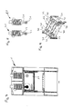
- the press 1 according to the Fig. 1 to 9 has a press table 10, a press frame 12, a machine head or press head 14 and a plunger 16.
- the machine head 14 may also be referred to as the machine upper part or press upper part.
- the press frame 12 has four columns 18 in the present embodiment.
- a plurality of drives 20 are provided, which are each here as a linear electric motor 20, and in particular designed as a servomotor linear electric motor, are formed.
- Fig. 1 how good the Fig. 1 can be removed, 14 chambers 22a, 22b, 22c and 22d are formed in this embodiment in the press upper part or press head, in each of which one of the linear electric motors 20 is arranged. In this embodiment, four linear electric motors 20 are provided, but the number may also vary.
- linear electric motors 20 can alternatively also be integrated in the press table 10, as a result of which installation space can be saved upwards.
- a lateral arrangement of the linear electric motors 20 may alternatively be provided.
- the columns 18 of the press frame 20 are arranged on the four corners of an imaginary rectangular contour.
- the columns 18 are here so that they carry the press head 14.
- the linear electric motors 20 each have a designed as a drive axis 24 linearly displaceable part, which can be moved axially during operation of the linear electric motor 20 and axially moved back and forth, in particular by means of a or a plurality of magnetic fields or by means of a plurality of magnetic poles of the linear electric motor 20th
- an eye 26 is provided on the linear electric motor 20 far end of the drive shaft 24, wherein this eye 26 of the coupling with the plunger 16 is used.
- the plunger 16 has a substantially rectangular outer contour and is designed so that it ensures the best possible rigidity. In the exemplary embodiment, this is so that four plates 28, 30, 32, 34 which are essentially height-related form a kind of rectangular frame, the parallel plates 32 and 34 forming short sides and the parallel plates 28 and 30 forming long sides of a rectangle , However, the short sides 34, 32 may be longer than the spacing of the plates 28 and 30, so that the Plates 32, 34 end over the plate 28 and 30 protrude.
- triangular plates 36 are formed on the respective abutting plates in the region in which each of the shorter plates 32, 34 project beyond the plates 28, 30. In the exemplary embodiment shown, this is such that three triangular plates 36 are integrally formed in each of these corner areas, one bottom, one top and one substantially in the middle being formed.
- plates 38, 40 are provided, which here connect the plates 32 and 34 and, for example - as in Fig. 9 shown - parallel to the plates 28 and 30 run. It could, however, also be provided, for example, that stiffening plates in the manner of a truss pattern are arranged within the frame.
- a bolt extends through two plates for each of the linear electric motors 20. This is so here that two bolts 42 are respectively mounted in the plate 30 and the adjacent plate 40 and two bolts 42 are respectively mounted in the plate 28 and in the adjacent plate 40. In this state, these bolts 42 each extend through an eye 26 of a linear electric motor 20th
- the plunger 16 further includes a bottom plate 44 which Fig. 2 can be seen.
- the bottom plate 44 has a first receiving area 46 for receiving a tool, not shown.
- the receiving region 46 has a plurality of grooves 48, which are designed T-shaped in this embodiment.
- the press table 10 or the press table top has a second receiving area on its upper side 50 for a second tool, which is also not shown.
- This second receiving region 50 is formed by a plurality of grooves 52, which for example likewise have a T-shaped cross-sectional profile, or has such.
- the linear electric motors 20 are positioned in the press table 10, for example, corresponding power transmission paths, which are formed for example by L-shaped parts and which provide the coupling to the plunger, in the region of the press frame or run between the columns of the press frame.
- the in the Fig. 1 to 9 The design shown can be, for example, part of a stamping machine or part of a cutting machine or part of a thermoforming machine.
- the invention has various advantages. So it offers a high variability, that means in particular a freely programmable ram speed in every position. Furthermore, tryout operation is possible.
- the design can be used according to a Exzenterstanzautomat or according to a hydraulic press. It is also advantageous that no more synthetic lubricating or hydraulic oils are required. Next occur no rotating bearings, so no lubrication required is.
- the invention offers a high degree of variability, at least in its developments.
- the linear movement of the plunger 16 is realized directly by a linear movement of the drive. There is no or no conversion of a rotational to a linear movement. Thus, less energy losses occur.
- Fig. 10 shows a second embodiment of the invention in a schematic view, wherein like or corresponding parts are provided with the reference numerals, which are also in the Fig. 1 to 9 were used.
- the design according to Fig. 10 corresponds essentially to the design according to the Fig. 1 to 9 so that on the Fig. 1 to 9 subject to the following deviations also for the design according to Fig. 10 applies.
- Fig. 10 is the arrangement of the linear electric motors 20 - here, for example, four may be provided - different from the design according to the Fig. 1 to 9 not in the press head 14, but in the press table 10, so that the corresponding power transmission path to the plunger 16 is modified accordingly.
- the drive shaft 24 is connected to an angle 60 which engages laterally in the plunger 16.
- the drive axle 24 without Interposition of an angle be connected directly to the plunger 16, for example, laterally or from below.
- embodiments of the invention there are fewer health problems for persons than in the design according to him EP 0 943 422 A2 because the magnetic fields do not have to be that strong.
- the magnetic fields can be easily shielded.
- embodiments of the invention can be made oil and / or fat free.
- the arrangement of the linear electric motors 20 in the press table 10 usually saves space upwards.
- the power transmission path from the linear electric motor 20 to the plunger 16 can be formed for example by the drive axle 24 and / or rods, so that the access to the working area 62 not appreciably, or at least to a lesser extent than in the design according to the EP 0 943 422 A2 , is impaired.
- Fig. 11 to 13 show an exemplary linear electric motor 20, the inventive designs, such as in the design as a drive for the plunger 16 can be used in the Fig. 1 to 9 is shown, or in the design, in Fig. 10 is shown.
- Fig. 11 is a front view of the linear electric motor 20, while Fig. 12 a section along the line XII-XII Fig. 11 shows and while Fig. 13 a section along the line XIII-XIII Fig. 11 shows.
- the linear electric motor 20 has a plurality of magnetic poles 70, 72, 74, 76, 78, 80, which are arranged offset axially relative to the central longitudinal axis 82 of the linear electric motor 20.
- poles 70, 72, 74, 76, 78, 80 are formed by means of coils 84, 86, 88, which are also arranged axially offset with respect to the central longitudinal axis 82.
- Each of these coils 84, 86, 88 is wound on a bobbin 90, 92, 94 on its radially outer surface.
- each of the coils 84, 86, 88 are traversed by an electric current and is accordingly made of suitable, electrically conductive material, such as metal, in particular copper.
- suitable, electrically conductive material such as metal, in particular copper.
- each of the coils 84, 86, 88 is wound from a corresponding wire.
- the magnetic field forming as a result of the current flow through the respective coil 84, 86, 88 then generates in each case one plus pole and one negative pole in the interior 96, which will be discussed below.
- the magnetic poles 70, 72, 74, 76, 78, 80 must or should therefore not permanently act as positive pole or negative pole, but rather can be made by energizing the respectively corresponding coil to a positive pole or negative pole. This is particularly so that, if one of these coils 84, 86, 88 is traversed by an electric current, the relevant Coil 84, 86, 88 generates a magnetic field with its associated previously addressed poles 70 and 72, or 74 and 76, or 78 and 80. In the above-mentioned pairwise order, these poles are assigned to the coils 84, 86 and 88.
- poles 70, 72, 74, 76, 78, 80 need not be physically tangible, and thus can be formed by the magnetic field itself.
- Each of the coil supports 90, 92, 94 may also be made of electrically conductive material, such as metal, in particular copper, or of an electrically insulating material.
- a linearly displaceable part is arranged, which is also referred to as rotor or drive axle 24, and in the direction of the axis 82 by means of the coils 84, 86th , 88 is axially displaceable.
- This drive axle 24 is completely or partially designed as a permanent magnet and accordingly forms magnetic poles 100, 102 at its axial ends 104, 106.
- the drive shaft 24 may be provided with an eye 26 for coupling to the plunger 16, or be fixedly coupled to an intermediate portion 107, which in turn has the eye 26. Instead of the eye 26, however, a differently designed coupling point for the plunger 16 may be provided.
- Axial between the coils 84, 86, 88 and / or coil supports 90, 92, 94 may be provided electrical and / or magnetic insulators 108, 110, however, have radially inwardly through holes 112, so that the rotor 24 can enter or pass unhindered ,
- a switching device 140 is provided, by means of which optionally one, possibly also simultaneously or temporally overlapping a plurality of the coils 84, 86, 88 is coupled to the electrical voltage source 138 such that the relevant coil 84, 86, 88 of an electric Current is flowing through and the coil 84, 86, 88 associated with these poles 70, 72, 74, 76, 78, 80, ie magnetic plus pole and magnetic negative pole, training or be activated.
- a control device 142 which the energization of the coils 84, 86, 88 and / or the switching positions of the switching device 140 to cause the respectively desired axial displacement of the rotor 24, and thus of the plunger 16.
- This control device 142 which may also have other control functions, such as the control of the workpiece movement by the press, controls the coils 84, 86, 88 in a defined order, so as to effect the respective desired axial displacement of the rotor 24.
- the driving takes place so that the axial displacement by the respective interaction of the poles 100, 102 of the rotor 24 with the forming poles 70, 72, 74, 76, 78, 80 of the respective energized coil 84, 86, 88, comes about. It is exploited that the same magnetic poles, ie two Magnetic positive poles or two magnetic negative poles, repelled and different poles, ie a positive magnetic pole and a negative magnetic pole, tighten.
- the drive shaft 24, and thus the plunger 16 can be moved axially, optionally in either one of the two opposite orientations.
- the drive shaft 24, and thus the plunger 16 with the tool mounted or held thereon can thus be reciprocated for machining the workpiece.
- This movement can also be controlled by means of the control device 142 so that it is tuned to the feed of the workpiece and its timing.
- the drive shaft 24 can be stopped and held in predetermined axial positions or in any axial position of its axial travel range.
- - depending on the desired holding position and / or number of coils 84, 86, 88 - one or more coils 84, 86, 88 are energized such that in the desired position by means of the poles 70th , 72, 74, 76, 78, 80 of the currently energized coils 84, 86, 88 an axial force equilibrium on the drive axle 24 is generated.
- power relationships can also be a damped braking movement of the drive shaft 24 are generated.
- the corresponding tuning of the current supply in the one or more coils 84, 86, 88 can be controlled by the control device 142.
- a plurality of coils 84, 86, 88 can also be supplied with current at the same time or overlapping in time.
- the respective axial position can also be determined by calculation in the control device 142 as a function of previous control characteristics.
- a rotation lock for the rotor 24 may be present, which counteracts a rotation of the rotor 24 about the axis 82. While in the Fig. 11 to 13 the bobbin carriers 90, 92, 94 are hollow cylindrical and the rotor 24 are shown cylindrically, but other cross-sectional shapes, such as, for example, triangular, quadrangular, pentagonal, hexagonal or the like may also be provided in each case.
Landscapes
- Engineering & Computer Science (AREA)
- Mechanical Engineering (AREA)
- Life Sciences & Earth Sciences (AREA)
- Forests & Forestry (AREA)
- Physics & Mathematics (AREA)
- Electromagnetism (AREA)
- Press Drives And Press Lines (AREA)
- Pharmaceuticals Containing Other Organic And Inorganic Compounds (AREA)
Priority Applications (1)
| Application Number | Priority Date | Filing Date | Title |
|---|---|---|---|
| SI201031294A SI2329944T1 (sl) | 2009-12-03 | 2010-11-22 | Stiskalnica za generiranje stiskalne sile za obdelovanje obdelovanca |
Applications Claiming Priority (1)
| Application Number | Priority Date | Filing Date | Title |
|---|---|---|---|
| AT19142009A AT509090B1 (de) | 2009-12-03 | 2009-12-03 | Presse zum erzeugen einer druckkraft für die bearbeitung eines werkstücks |
Publications (3)
| Publication Number | Publication Date |
|---|---|
| EP2329944A2 true EP2329944A2 (fr) | 2011-06-08 |
| EP2329944A3 EP2329944A3 (fr) | 2013-09-18 |
| EP2329944B1 EP2329944B1 (fr) | 2016-08-31 |
Family
ID=43502553
Family Applications (1)
| Application Number | Title | Priority Date | Filing Date |
|---|---|---|---|
| EP10014816.2A Active EP2329944B1 (fr) | 2009-12-03 | 2010-11-22 | Presse destinée à produire une force de pression pour le traitement d'une pièce |
Country Status (8)
| Country | Link |
|---|---|
| EP (1) | EP2329944B1 (fr) |
| AT (1) | AT509090B1 (fr) |
| EA (1) | EA023188B1 (fr) |
| ES (1) | ES2603981T3 (fr) |
| HU (1) | HUE030662T2 (fr) |
| PL (1) | PL2329944T3 (fr) |
| SI (1) | SI2329944T1 (fr) |
| UA (1) | UA108189C2 (fr) |
Cited By (5)
| Publication number | Priority date | Publication date | Assignee | Title |
|---|---|---|---|---|
| CN102886563A (zh) * | 2012-10-19 | 2013-01-23 | 无锡市百顺机械厂 | 一种具有加速增力功能的液压剪板机活动刀架 |
| WO2013034782A1 (fr) * | 2011-09-06 | 2013-03-14 | Gaindu, S.L. | Machine pour la fracture d'une bielle |
| CN105107924A (zh) * | 2015-09-25 | 2015-12-02 | 东莞市锐祥智能卡科技有限公司 | 一种多尺寸芯片冲切设备 |
| CN108787972A (zh) * | 2018-06-15 | 2018-11-13 | 郭小红 | 智能化直驱电磁锻造锤 |
| DE102020206223A1 (de) | 2020-05-18 | 2021-11-18 | Sms Group Gmbh | Querhaupt zur Verwendung als Ober- und/oder Unterholm in einer Presse |
Families Citing this family (1)
| Publication number | Priority date | Publication date | Assignee | Title |
|---|---|---|---|---|
| DE102019110889B4 (de) * | 2019-04-26 | 2024-08-22 | Langenstein & Schemann Gmbh | Antriebseinheit mit Linearantrieben für eine Umformmaschine und Umformmaschine mit einer solchen Antriebseinheit |
Citations (1)
| Publication number | Priority date | Publication date | Assignee | Title |
|---|---|---|---|---|
| EP0943422A2 (fr) | 1998-03-16 | 1999-09-22 | Yamada Dobby Co., Ltd. | Dispositif de commande du coulisseau dans une presse |
Family Cites Families (16)
| Publication number | Priority date | Publication date | Assignee | Title |
|---|---|---|---|---|
| US2597559A (en) * | 1949-07-18 | 1952-05-20 | Bekey Andrew | Electromagnetically operated mechanism using resonance effects |
| US2951437A (en) * | 1957-03-29 | 1960-09-06 | Elemag Anstalt | Electromagnetic press |
| SU500980A1 (ru) * | 1972-06-05 | 1976-01-30 | Электромагнитный пресс | |
| SU453327A1 (ru) * | 1973-08-13 | 1974-12-15 | Привод гидравлического пресса | |
| US4056029A (en) * | 1976-04-29 | 1977-11-01 | Doherty Norman R | Electrically actuated power press |
| SU629075A1 (ru) * | 1977-01-05 | 1978-10-25 | Свердловский Завод Пластмасс | Пресс дл полимерных материалов |
| JPS5985329A (ja) * | 1982-11-09 | 1984-05-17 | Amada Co Ltd | 打ち抜きプレスの打撃装置 |
| US5357779A (en) * | 1990-09-07 | 1994-10-25 | Coors Brewing Company | Can body maker with magnetic ram bearing and redraw actuator |
| JP2001352747A (ja) * | 2000-06-09 | 2001-12-21 | Aida Eng Ltd | リニアモータおよびこれを駆動源とするプレス成形装置 |
| CN100421921C (zh) * | 2001-04-26 | 2008-10-01 | 沙迪克株式会社 | 压力机械与机床 |
| JP2008043993A (ja) * | 2006-08-21 | 2008-02-28 | Murata Mach Ltd | リニアモータ搭載プレス機械 |
| KR20080017229A (ko) * | 2006-08-21 | 2008-02-26 | 무라타 기카이 가부시키가이샤 | 리니어 모터 및 그것을 탑재한 공작기계 |
| JP2008043992A (ja) * | 2006-08-21 | 2008-02-28 | Murata Mach Ltd | リニアモータ搭載プレス機械 |
| JP2008043991A (ja) * | 2006-08-21 | 2008-02-28 | Murata Mach Ltd | リニアモータ搭載プレス機械 |
| JP5100073B2 (ja) * | 2006-09-28 | 2012-12-19 | 村田機械株式会社 | リニアモータ装置およびそれを搭載した工作機械 |
| JP2008086144A (ja) * | 2006-09-28 | 2008-04-10 | Murata Mach Ltd | リニアモータおよびそれを搭載した工作機械 |
-
2009
- 2009-12-03 AT AT19142009A patent/AT509090B1/de active
-
2010
- 2010-11-22 PL PL10014816T patent/PL2329944T3/pl unknown
- 2010-11-22 ES ES10014816.2T patent/ES2603981T3/es active Active
- 2010-11-22 EP EP10014816.2A patent/EP2329944B1/fr active Active
- 2010-11-22 SI SI201031294A patent/SI2329944T1/sl unknown
- 2010-11-22 HU HUE10014816A patent/HUE030662T2/en unknown
- 2010-12-02 EA EA201001743A patent/EA023188B1/ru not_active IP Right Cessation
- 2010-12-02 UA UAA201014452A patent/UA108189C2/ru unknown
Patent Citations (1)
| Publication number | Priority date | Publication date | Assignee | Title |
|---|---|---|---|---|
| EP0943422A2 (fr) | 1998-03-16 | 1999-09-22 | Yamada Dobby Co., Ltd. | Dispositif de commande du coulisseau dans une presse |
Cited By (11)
| Publication number | Priority date | Publication date | Assignee | Title |
|---|---|---|---|---|
| WO2013034782A1 (fr) * | 2011-09-06 | 2013-03-14 | Gaindu, S.L. | Machine pour la fracture d'une bielle |
| GB2498915A (en) * | 2011-09-06 | 2013-07-31 | Gaindu Sl | Machine for breaking a connecting rod |
| GB2498915B (en) * | 2011-09-06 | 2015-06-10 | Gaindu Sl | Machine for cracking a connecting rod |
| US9821387B2 (en) | 2011-09-06 | 2017-11-21 | Gaindu, S.L. | Machine for breaking a connecting rod |
| CN102886563A (zh) * | 2012-10-19 | 2013-01-23 | 无锡市百顺机械厂 | 一种具有加速增力功能的液压剪板机活动刀架 |
| CN102886563B (zh) * | 2012-10-19 | 2015-09-02 | 江苏高博智融科技有限公司 | 一种具有加速增力功能的液压剪板机活动刀架 |
| CN105107924A (zh) * | 2015-09-25 | 2015-12-02 | 东莞市锐祥智能卡科技有限公司 | 一种多尺寸芯片冲切设备 |
| CN105107924B (zh) * | 2015-09-25 | 2017-04-26 | 东莞市锐祥智能卡科技有限公司 | 一种多尺寸芯片冲切设备 |
| CN108787972A (zh) * | 2018-06-15 | 2018-11-13 | 郭小红 | 智能化直驱电磁锻造锤 |
| CN108787972B (zh) * | 2018-06-15 | 2024-05-24 | 郭小红 | 智能化直驱电磁锻造锤 |
| DE102020206223A1 (de) | 2020-05-18 | 2021-11-18 | Sms Group Gmbh | Querhaupt zur Verwendung als Ober- und/oder Unterholm in einer Presse |
Also Published As
| Publication number | Publication date |
|---|---|
| EA201001743A1 (ru) | 2011-06-30 |
| SI2329944T1 (sl) | 2017-02-28 |
| ES2603981T3 (es) | 2017-03-02 |
| AT509090A1 (de) | 2011-06-15 |
| HUE030662T2 (en) | 2017-05-29 |
| PL2329944T3 (pl) | 2017-02-28 |
| UA108189C2 (uk) | 2015-04-10 |
| AT509090B1 (de) | 2014-03-15 |
| EA023188B1 (ru) | 2016-05-31 |
| EP2329944A3 (fr) | 2013-09-18 |
| EP2329944B1 (fr) | 2016-08-31 |
Similar Documents
| Publication | Publication Date | Title |
|---|---|---|
| EP2527058B1 (fr) | Machine-outil sous la forme d'une presse pour le traitement de pièces usinées, notamment de tôles | |
| DE3620741C2 (fr) | ||
| EP2329944B1 (fr) | Presse destinée à produire une force de pression pour le traitement d'une pièce | |
| DE3110221A1 (de) | Stanzpresse | |
| DE2738344A1 (de) | Werkzeugmaschine, insbesondere stanzmaschine | |
| DE3012486A1 (de) | Vorrichtung nach art einer stanze oder presse | |
| EP0121826A2 (fr) | Outil de découpage et de cintrage | |
| WO2013056805A1 (fr) | Presse | |
| DE60222101T2 (de) | Vorrichtung zum antreiben und damit hergestelltes spannwerkeug | |
| DE2741576A1 (de) | Bearbeitungsmaschine fuer draht und band, insbesondere stanz- und biegeautomat, mit mehreren werkzeugebenen | |
| EP2768662B1 (fr) | Presse | |
| DE102008060043B3 (de) | Spindelpresse | |
| EP0739663B1 (fr) | Machine pour former des pièces | |
| DE102011113624B4 (de) | Modulares Antriebssystem für eine Umformmaschine | |
| DE102009055739A1 (de) | Umformmaschine, insbesondere Servopresse | |
| DE19745342B4 (de) | Tischhebeeinrichtung für eine Werkzeugmaschine | |
| DE68913337T2 (de) | Stufenumformpresse und Verfahren zu ihrer Herstellung. | |
| AT510052A1 (de) | Antriebseinheit für einen stanzautomat oder eine presse | |
| DE202013103426U1 (de) | Vorrichtung zur Erzeugung einer Bohrung in einem Werkstück oder eines Gewindes in einer Bohrung eines Werkstücks | |
| EP2114587B1 (fr) | Presse de formage présentant une fonction de coussin pneumatique intégrée au plateau coulissant | |
| EP3024646B1 (fr) | Module de force et système de pressage modulaire | |
| DE10063154B4 (de) | Schmiedepresse mit Stellvorrichtung auf Matrizenseite | |
| EP1663564A1 (fr) | Pince porte-electrode | |
| EP3095534B1 (fr) | Cintreuse | |
| EP3025803B1 (fr) | Dispositif d'entraînement pour une machine-outil et machine-outil dotée d'un tel dispositif d'entraînement |
Legal Events
| Date | Code | Title | Description |
|---|---|---|---|
| PUAI | Public reference made under article 153(3) epc to a published international application that has entered the european phase |
Free format text: ORIGINAL CODE: 0009012 |
|
| AK | Designated contracting states |
Kind code of ref document: A2 Designated state(s): AL AT BE BG CH CY CZ DE DK EE ES FI FR GB GR HR HU IE IS IT LI LT LU LV MC MK MT NL NO PL PT RO RS SE SI SK SM TR |
|
| AX | Request for extension of the european patent |
Extension state: BA ME |
|
| PUAL | Search report despatched |
Free format text: ORIGINAL CODE: 0009013 |
|
| AK | Designated contracting states |
Kind code of ref document: A3 Designated state(s): AL AT BE BG CH CY CZ DE DK EE ES FI FR GB GR HR HU IE IS IT LI LT LU LV MC MK MT NL NO PL PT RO RS SE SI SK SM TR |
|
| AX | Request for extension of the european patent |
Extension state: BA ME |
|
| RIC1 | Information provided on ipc code assigned before grant |
Ipc: B26D 5/08 20060101ALI20130809BHEP Ipc: B30B 1/42 20060101AFI20130809BHEP Ipc: B30B 1/10 20060101ALI20130809BHEP Ipc: B21J 7/30 20060101ALI20130809BHEP |
|
| 17P | Request for examination filed |
Effective date: 20140319 |
|
| RBV | Designated contracting states (corrected) |
Designated state(s): AL AT BE BG CH CY CZ DE DK EE ES FI FR GB GR HR HU IE IS IT LI LT LU LV MC MK MT NL NO PL PT RO RS SE SI SK SM TR |
|
| 17Q | First examination report despatched |
Effective date: 20150831 |
|
| RIC1 | Information provided on ipc code assigned before grant |
Ipc: B30B 1/42 20060101AFI20160405BHEP Ipc: B26D 5/08 20060101ALI20160405BHEP Ipc: B21J 7/30 20060101ALI20160405BHEP Ipc: B26F 1/40 20060101ALI20160405BHEP Ipc: B21J 9/10 20060101ALI20160405BHEP Ipc: B30B 1/10 20060101ALI20160405BHEP |
|
| GRAP | Despatch of communication of intention to grant a patent |
Free format text: ORIGINAL CODE: EPIDOSNIGR1 |
|
| INTG | Intention to grant announced |
Effective date: 20160531 |
|
| GRAS | Grant fee paid |
Free format text: ORIGINAL CODE: EPIDOSNIGR3 |
|
| GRAA | (expected) grant |
Free format text: ORIGINAL CODE: 0009210 |
|
| AK | Designated contracting states |
Kind code of ref document: B1 Designated state(s): AL AT BE BG CH CY CZ DE DK EE ES FI FR GB GR HR HU IE IS IT LI LT LU LV MC MK MT NL NO PL PT RO RS SE SI SK SM TR |
|
| REG | Reference to a national code |
Ref country code: CH Ref legal event code: EP Ref country code: GB Ref legal event code: FG4D Free format text: NOT ENGLISH |
|
| REG | Reference to a national code |
Ref country code: IE Ref legal event code: FG4D Free format text: LANGUAGE OF EP DOCUMENT: GERMAN |
|
| REG | Reference to a national code |
Ref country code: DE Ref legal event code: R096 Ref document number: 502010012284 Country of ref document: DE |
|
| REG | Reference to a national code |
Ref country code: AT Ref legal event code: REF Ref document number: 824630 Country of ref document: AT Kind code of ref document: T Effective date: 20161015 |
|
| REG | Reference to a national code |
Ref country code: FR Ref legal event code: PLFP Year of fee payment: 7 |
|
| REG | Reference to a national code |
Ref country code: LT Ref legal event code: MG4D |
|
| REG | Reference to a national code |
Ref country code: NL Ref legal event code: MP Effective date: 20160831 |
|
| PG25 | Lapsed in a contracting state [announced via postgrant information from national office to epo] |
Ref country code: HR Free format text: LAPSE BECAUSE OF FAILURE TO SUBMIT A TRANSLATION OF THE DESCRIPTION OR TO PAY THE FEE WITHIN THE PRESCRIBED TIME-LIMIT Effective date: 20160831 Ref country code: RS Free format text: LAPSE BECAUSE OF FAILURE TO SUBMIT A TRANSLATION OF THE DESCRIPTION OR TO PAY THE FEE WITHIN THE PRESCRIBED TIME-LIMIT Effective date: 20160831 Ref country code: FI Free format text: LAPSE BECAUSE OF FAILURE TO SUBMIT A TRANSLATION OF THE DESCRIPTION OR TO PAY THE FEE WITHIN THE PRESCRIBED TIME-LIMIT Effective date: 20160831 Ref country code: NO Free format text: LAPSE BECAUSE OF FAILURE TO SUBMIT A TRANSLATION OF THE DESCRIPTION OR TO PAY THE FEE WITHIN THE PRESCRIBED TIME-LIMIT Effective date: 20161130 Ref country code: LT Free format text: LAPSE BECAUSE OF FAILURE TO SUBMIT A TRANSLATION OF THE DESCRIPTION OR TO PAY THE FEE WITHIN THE PRESCRIBED TIME-LIMIT Effective date: 20160831 |
|
| PG25 | Lapsed in a contracting state [announced via postgrant information from national office to epo] |
Ref country code: BE Free format text: LAPSE BECAUSE OF NON-PAYMENT OF DUE FEES Effective date: 20161130 Ref country code: SE Free format text: LAPSE BECAUSE OF FAILURE TO SUBMIT A TRANSLATION OF THE DESCRIPTION OR TO PAY THE FEE WITHIN THE PRESCRIBED TIME-LIMIT Effective date: 20160831 Ref country code: NL Free format text: LAPSE BECAUSE OF FAILURE TO SUBMIT A TRANSLATION OF THE DESCRIPTION OR TO PAY THE FEE WITHIN THE PRESCRIBED TIME-LIMIT Effective date: 20160831 Ref country code: GR Free format text: LAPSE BECAUSE OF FAILURE TO SUBMIT A TRANSLATION OF THE DESCRIPTION OR TO PAY THE FEE WITHIN THE PRESCRIBED TIME-LIMIT Effective date: 20161201 Ref country code: LV Free format text: LAPSE BECAUSE OF FAILURE TO SUBMIT A TRANSLATION OF THE DESCRIPTION OR TO PAY THE FEE WITHIN THE PRESCRIBED TIME-LIMIT Effective date: 20160831 |
|
| PG25 | Lapsed in a contracting state [announced via postgrant information from national office to epo] |
Ref country code: EE Free format text: LAPSE BECAUSE OF FAILURE TO SUBMIT A TRANSLATION OF THE DESCRIPTION OR TO PAY THE FEE WITHIN THE PRESCRIBED TIME-LIMIT Effective date: 20160831 Ref country code: RO Free format text: LAPSE BECAUSE OF FAILURE TO SUBMIT A TRANSLATION OF THE DESCRIPTION OR TO PAY THE FEE WITHIN THE PRESCRIBED TIME-LIMIT Effective date: 20160831 |
|
| REG | Reference to a national code |
Ref country code: HU Ref legal event code: AG4A Ref document number: E030662 Country of ref document: HU |
|
| PG25 | Lapsed in a contracting state [announced via postgrant information from national office to epo] |
Ref country code: DK Free format text: LAPSE BECAUSE OF FAILURE TO SUBMIT A TRANSLATION OF THE DESCRIPTION OR TO PAY THE FEE WITHIN THE PRESCRIBED TIME-LIMIT Effective date: 20160831 Ref country code: BG Free format text: LAPSE BECAUSE OF FAILURE TO SUBMIT A TRANSLATION OF THE DESCRIPTION OR TO PAY THE FEE WITHIN THE PRESCRIBED TIME-LIMIT Effective date: 20161130 Ref country code: SM Free format text: LAPSE BECAUSE OF FAILURE TO SUBMIT A TRANSLATION OF THE DESCRIPTION OR TO PAY THE FEE WITHIN THE PRESCRIBED TIME-LIMIT Effective date: 20160831 Ref country code: PT Free format text: LAPSE BECAUSE OF FAILURE TO SUBMIT A TRANSLATION OF THE DESCRIPTION OR TO PAY THE FEE WITHIN THE PRESCRIBED TIME-LIMIT Effective date: 20170102 Ref country code: SK Free format text: LAPSE BECAUSE OF FAILURE TO SUBMIT A TRANSLATION OF THE DESCRIPTION OR TO PAY THE FEE WITHIN THE PRESCRIBED TIME-LIMIT Effective date: 20160831 |
|
| REG | Reference to a national code |
Ref country code: DE Ref legal event code: R097 Ref document number: 502010012284 Country of ref document: DE |
|
| REG | Reference to a national code |
Ref country code: CH Ref legal event code: PL |
|
| PLBE | No opposition filed within time limit |
Free format text: ORIGINAL CODE: 0009261 |
|
| STAA | Information on the status of an ep patent application or granted ep patent |
Free format text: STATUS: NO OPPOSITION FILED WITHIN TIME LIMIT |
|
| GBPC | Gb: european patent ceased through non-payment of renewal fee |
Effective date: 20161130 |
|
| PG25 | Lapsed in a contracting state [announced via postgrant information from national office to epo] |
Ref country code: LI Free format text: LAPSE BECAUSE OF NON-PAYMENT OF DUE FEES Effective date: 20161130 Ref country code: CH Free format text: LAPSE BECAUSE OF NON-PAYMENT OF DUE FEES Effective date: 20161130 |
|
| 26N | No opposition filed |
Effective date: 20170601 |
|
| REG | Reference to a national code |
Ref country code: IE Ref legal event code: MM4A |
|
| PG25 | Lapsed in a contracting state [announced via postgrant information from national office to epo] |
Ref country code: LU Free format text: LAPSE BECAUSE OF NON-PAYMENT OF DUE FEES Effective date: 20161130 |
|
| REG | Reference to a national code |
Ref country code: FR Ref legal event code: PLFP Year of fee payment: 8 |
|
| PG25 | Lapsed in a contracting state [announced via postgrant information from national office to epo] |
Ref country code: GB Free format text: LAPSE BECAUSE OF NON-PAYMENT OF DUE FEES Effective date: 20161130 Ref country code: IE Free format text: LAPSE BECAUSE OF NON-PAYMENT OF DUE FEES Effective date: 20161122 |
|
| REG | Reference to a national code |
Ref country code: AT Ref legal event code: MM01 Ref document number: 824630 Country of ref document: AT Kind code of ref document: T Effective date: 20161122 |
|
| PG25 | Lapsed in a contracting state [announced via postgrant information from national office to epo] |
Ref country code: AT Free format text: LAPSE BECAUSE OF NON-PAYMENT OF DUE FEES Effective date: 20161122 |
|
| REG | Reference to a national code |
Ref country code: BE Ref legal event code: MM Effective date: 20161130 |
|
| PG25 | Lapsed in a contracting state [announced via postgrant information from national office to epo] |
Ref country code: CY Free format text: LAPSE BECAUSE OF FAILURE TO SUBMIT A TRANSLATION OF THE DESCRIPTION OR TO PAY THE FEE WITHIN THE PRESCRIBED TIME-LIMIT Effective date: 20160831 |
|
| PG25 | Lapsed in a contracting state [announced via postgrant information from national office to epo] |
Ref country code: MK Free format text: LAPSE BECAUSE OF FAILURE TO SUBMIT A TRANSLATION OF THE DESCRIPTION OR TO PAY THE FEE WITHIN THE PRESCRIBED TIME-LIMIT Effective date: 20160831 Ref country code: IS Free format text: LAPSE BECAUSE OF FAILURE TO SUBMIT A TRANSLATION OF THE DESCRIPTION OR TO PAY THE FEE WITHIN THE PRESCRIBED TIME-LIMIT Effective date: 20160831 Ref country code: MC Free format text: LAPSE BECAUSE OF FAILURE TO SUBMIT A TRANSLATION OF THE DESCRIPTION OR TO PAY THE FEE WITHIN THE PRESCRIBED TIME-LIMIT Effective date: 20160831 |
|
| PG25 | Lapsed in a contracting state [announced via postgrant information from national office to epo] |
Ref country code: MT Free format text: LAPSE BECAUSE OF FAILURE TO SUBMIT A TRANSLATION OF THE DESCRIPTION OR TO PAY THE FEE WITHIN THE PRESCRIBED TIME-LIMIT Effective date: 20160831 |
|
| PG25 | Lapsed in a contracting state [announced via postgrant information from national office to epo] |
Ref country code: AL Free format text: LAPSE BECAUSE OF FAILURE TO SUBMIT A TRANSLATION OF THE DESCRIPTION OR TO PAY THE FEE WITHIN THE PRESCRIBED TIME-LIMIT Effective date: 20160831 |
|
| PGFP | Annual fee paid to national office [announced via postgrant information from national office to epo] |
Ref country code: HU Payment date: 20211117 Year of fee payment: 12 |
|
| PGFP | Annual fee paid to national office [announced via postgrant information from national office to epo] |
Ref country code: PL Payment date: 20211116 Year of fee payment: 12 |
|
| PG25 | Lapsed in a contracting state [announced via postgrant information from national office to epo] |
Ref country code: HU Free format text: LAPSE BECAUSE OF NON-PAYMENT OF DUE FEES Effective date: 20221123 |
|
| PGFP | Annual fee paid to national office [announced via postgrant information from national office to epo] |
Ref country code: TR Payment date: 20231120 Year of fee payment: 14 |
|
| PG25 | Lapsed in a contracting state [announced via postgrant information from national office to epo] |
Ref country code: PL Free format text: LAPSE BECAUSE OF NON-PAYMENT OF DUE FEES Effective date: 20221122 |
|
| PGFP | Annual fee paid to national office [announced via postgrant information from national office to epo] |
Ref country code: DE Payment date: 20251119 Year of fee payment: 16 |
|
| PGFP | Annual fee paid to national office [announced via postgrant information from national office to epo] |
Ref country code: IT Payment date: 20251125 Year of fee payment: 16 |
|
| PGFP | Annual fee paid to national office [announced via postgrant information from national office to epo] |
Ref country code: FR Payment date: 20251124 Year of fee payment: 16 |
|
| PGFP | Annual fee paid to national office [announced via postgrant information from national office to epo] |
Ref country code: CZ Payment date: 20251119 Year of fee payment: 16 |
|
| PGFP | Annual fee paid to national office [announced via postgrant information from national office to epo] |
Ref country code: ES Payment date: 20251229 Year of fee payment: 16 Ref country code: SI Payment date: 20251113 Year of fee payment: 16 |