EP2329986B1 - Ensemble formant siège pliable à plat et son entraînement - Google Patents
Ensemble formant siège pliable à plat et son entraînement Download PDFInfo
- Publication number
- EP2329986B1 EP2329986B1 EP11000345A EP11000345A EP2329986B1 EP 2329986 B1 EP2329986 B1 EP 2329986B1 EP 11000345 A EP11000345 A EP 11000345A EP 11000345 A EP11000345 A EP 11000345A EP 2329986 B1 EP2329986 B1 EP 2329986B1
- Authority
- EP
- European Patent Office
- Prior art keywords
- seat
- seat back
- assembly
- seat cushion
- floor
- Prior art date
- Legal status (The legal status is an assumption and is not a legal conclusion. Google has not performed a legal analysis and makes no representation as to the accuracy of the status listed.)
- Ceased
Links
- 230000007246 mechanism Effects 0.000 claims description 34
- 230000004044 response Effects 0.000 claims description 14
- 210000001364 upper extremity Anatomy 0.000 description 13
- 230000000712 assembly Effects 0.000 description 3
- 238000000429 assembly Methods 0.000 description 3
- 238000013459 approach Methods 0.000 description 2
- 230000001413 cellular effect Effects 0.000 description 2
- 239000006260 foam Substances 0.000 description 2
- 230000008878 coupling Effects 0.000 description 1
- 238000010168 coupling process Methods 0.000 description 1
- 238000005859 coupling reaction Methods 0.000 description 1
- 230000001419 dependent effect Effects 0.000 description 1
- 238000000034 method Methods 0.000 description 1
- 238000012986 modification Methods 0.000 description 1
- 230000004048 modification Effects 0.000 description 1
- 230000000284 resting effect Effects 0.000 description 1
Images







Classifications
-
- B—PERFORMING OPERATIONS; TRANSPORTING
- B60—VEHICLES IN GENERAL
- B60N—SEATS SPECIALLY ADAPTED FOR VEHICLES; VEHICLE PASSENGER ACCOMMODATION NOT OTHERWISE PROVIDED FOR
- B60N2/00—Seats specially adapted for vehicles; Arrangement or mounting of seats in vehicles
- B60N2/24—Seats specially adapted for vehicles; Arrangement or mounting of seats in vehicles for particular purposes or particular vehicles
- B60N2/30—Non-dismountable or dismountable seats storable in a non-use position, e.g. foldable spare seats
- B60N2/3002—Non-dismountable or dismountable seats storable in a non-use position, e.g. foldable spare seats back-rest movements
- B60N2/3004—Non-dismountable or dismountable seats storable in a non-use position, e.g. foldable spare seats back-rest movements by rotation only
- B60N2/3009—Non-dismountable or dismountable seats storable in a non-use position, e.g. foldable spare seats back-rest movements by rotation only about transversal axis
- B60N2/3013—Non-dismountable or dismountable seats storable in a non-use position, e.g. foldable spare seats back-rest movements by rotation only about transversal axis the back-rest being hinged on the vehicle frame
-
- B—PERFORMING OPERATIONS; TRANSPORTING
- B60—VEHICLES IN GENERAL
- B60N—SEATS SPECIALLY ADAPTED FOR VEHICLES; VEHICLE PASSENGER ACCOMMODATION NOT OTHERWISE PROVIDED FOR
- B60N2/00—Seats specially adapted for vehicles; Arrangement or mounting of seats in vehicles
- B60N2/24—Seats specially adapted for vehicles; Arrangement or mounting of seats in vehicles for particular purposes or particular vehicles
- B60N2/30—Non-dismountable or dismountable seats storable in a non-use position, e.g. foldable spare seats
-
- B—PERFORMING OPERATIONS; TRANSPORTING
- B60—VEHICLES IN GENERAL
- B60N—SEATS SPECIALLY ADAPTED FOR VEHICLES; VEHICLE PASSENGER ACCOMMODATION NOT OTHERWISE PROVIDED FOR
- B60N2/00—Seats specially adapted for vehicles; Arrangement or mounting of seats in vehicles
- B60N2/24—Seats specially adapted for vehicles; Arrangement or mounting of seats in vehicles for particular purposes or particular vehicles
- B60N2/30—Non-dismountable or dismountable seats storable in a non-use position, e.g. foldable spare seats
- B60N2/3038—Cushion movements
- B60N2/3063—Cushion movements by composed movement
- B60N2/3065—Cushion movements by composed movement in a longitudinal-vertical plane
-
- B—PERFORMING OPERATIONS; TRANSPORTING
- B60—VEHICLES IN GENERAL
- B60N—SEATS SPECIALLY ADAPTED FOR VEHICLES; VEHICLE PASSENGER ACCOMMODATION NOT OTHERWISE PROVIDED FOR
- B60N2/00—Seats specially adapted for vehicles; Arrangement or mounting of seats in vehicles
- B60N2/24—Seats specially adapted for vehicles; Arrangement or mounting of seats in vehicles for particular purposes or particular vehicles
- B60N2/30—Non-dismountable or dismountable seats storable in a non-use position, e.g. foldable spare seats
- B60N2/3088—Non-dismountable or dismountable seats storable in a non-use position, e.g. foldable spare seats characterised by the mechanical link
- B60N2/309—Non-dismountable or dismountable seats storable in a non-use position, e.g. foldable spare seats characterised by the mechanical link rods
-
- B—PERFORMING OPERATIONS; TRANSPORTING
- B60—VEHICLES IN GENERAL
- B60N—SEATS SPECIALLY ADAPTED FOR VEHICLES; VEHICLE PASSENGER ACCOMMODATION NOT OTHERWISE PROVIDED FOR
- B60N2/00—Seats specially adapted for vehicles; Arrangement or mounting of seats in vehicles
- B60N2/24—Seats specially adapted for vehicles; Arrangement or mounting of seats in vehicles for particular purposes or particular vehicles
- B60N2/32—Seats specially adapted for vehicles; Arrangement or mounting of seats in vehicles for particular purposes or particular vehicles convertible for other use
- B60N2/36—Seats specially adapted for vehicles; Arrangement or mounting of seats in vehicles for particular purposes or particular vehicles convertible for other use into a loading platform
-
- B—PERFORMING OPERATIONS; TRANSPORTING
- B60—VEHICLES IN GENERAL
- B60N—SEATS SPECIALLY ADAPTED FOR VEHICLES; VEHICLE PASSENGER ACCOMMODATION NOT OTHERWISE PROVIDED FOR
- B60N2/00—Seats specially adapted for vehicles; Arrangement or mounting of seats in vehicles
- B60N2/68—Seat frames
-
- B—PERFORMING OPERATIONS; TRANSPORTING
- B60—VEHICLES IN GENERAL
- B60N—SEATS SPECIALLY ADAPTED FOR VEHICLES; VEHICLE PASSENGER ACCOMMODATION NOT OTHERWISE PROVIDED FOR
- B60N2/00—Seats specially adapted for vehicles; Arrangement or mounting of seats in vehicles
- B60N2/80—Head-rests
- B60N2/806—Head-rests movable or adjustable
- B60N2/809—Head-rests movable or adjustable vertically slidable
- B60N2/832—Head-rests movable or adjustable vertically slidable movable to an inoperative or stowed position
- B60N2/835—Head-rests movable or adjustable vertically slidable movable to an inoperative or stowed position specially adapted for rear seats
Definitions
- the invention relates to a seat assembly for an automotive vehicle. More particularly, the invention relates to a seat assembly having a drive link for moving a seat cushion forward and downward along a floor of the vehicle in response to forwardly folding a seat back (see, for example, US 2004/0251705 A1 , corresponding to the preamble of claim 1).
- US 2004/0251705 A1 discloses a seat assembly for use in an automotive vehicle comprising a seat cushion and a seat back pivotally connected to the seat cushion by a recliner mechanism for providing pivotal movement of the seat back between a plurality of reclined seating positions and a forwardly folded position against the seat cushion.
- a front link supports the seat cushion above the floor of the vehicle in the seating position and lowers the seat cushion to a flat position with the seat back in the folded position.
- a rear floor latch releasably secures the seat cushion to the floor of the vehicle in the seating position and unlocks the seat cushion and the seat back for pivotal movement about the front link from the seating position to an upright tilted position with each of the seat cushion and the seat back extending generally upright from the floor of the vehicle.
- Automotive vehicles include one or more seat assemblies for supporting seat occupants within a passenger compartment of the vehicle.
- seat assemblies include a generally horizontal seat cushion spaced above a floor of the vehicle and a generally vertical seat back. It is well known in the seating art to provide a stowable seat assembly movable between a seating position for supporting the seat occupant above the floor and a stowed position lying flat against the floor, or nested within a recess formed in the floor.
- the seat back is pivotally coupled to the seat cushion for movement between a generally upright position and a folded position overlying the seat cushion.
- the seat cushion often includes a four bar linkage or front and rear legs extending between the seat cushion and the floor of the vehicle for moving the seat cushion between a raised position spaced above the floor and a lowered position resting along the floor.
- the pivotal movement of the seat back is actuated and controlled independently of the movement of the seat cushion, thus requiring separate operation of the seat back and seat cushion to move threat assembly from the seating position to the stowed position.
- a seat assembly for supporting an occupant above a floor in an automotive vehicle.
- the seat assembly includes a seat cushion that is adapted to be pivotally coupled to the floor for movement between a raised position spaced above the floor and a lowered position adjacent the floor.
- the seat assembly also includes a seat back that is adapted to be pivotally coupled to the floor for movement between an upright position and a folded position overlying the seat cushion.
- the seat assembly includes a drive link assembly operatively coupled between the seat back and the seat cushion for automatically moving the seat cushion between the raised and lowered positions in response to pivoting the seat back between the upright and folded positions thereby defining a seating position and a stowed position of the seat assembly.
- the seat assembly also includes a passive locking mechanism.
- the passive locking mechanism is operatively coupled between the seat back and the seat cushion for locking the seat back and seat cushion together when the seat assembly is in the seating position.
- a seat assembly in one embodiment, includes a seat cushion that is adapted to be pivotally coupled to a vehicle floor for movement between a raised position spaced above the floor and a lowered position adjacent the floor.
- the seat assembly also includes a seat back that is adapted to be pivotally coupled to the floor for movement between an upright position and a folded position overlying the seat cushion.
- the seat assembly further includes at least one drive link extending between a first end pivotally coupled to the seat back and a second end pivotally and slidably coupled to the seat cushion for automatically moving the seat cushion between the raised and lowered positions in response to pivoting the seat back between the upright and folded positions thereby defining a seating position and a stowed position of the seat assembly.
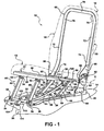
- Figure 1 is a front perspective view of a seat assembly in a seating position including a drive link assembly
- Figure 2 is a front perspective view of the seat assembly in a partially stowed position
- Figure 3 is a front perspective view of the seat assembly in a stowed position
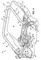
- Figure 4 is a rear perspective view of the seat assembly in the stowed position
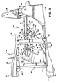
- Figure 5 is a fragmentary, front perspective view of the seat assembly in the seating position illustrating a passive locking mechanism
- Figure 6 is a fragmentary, front perspective view of the seat assembly in the partially stowed position illustrating the passive locking mechanism
- Figure 7 is a front perspective view of a seat assembly in a seating position according to an embodiment of the invention.
- Figure 8 is a front perspective view of the seat assembly of Figure 7 in a stowed position
- Figure 9 is a front perspective view of the seat assembly of Figure 7 in the seating position including a pair of drive links;
- Figure 10 is a front perspective view of the seat assembly of Figure 9 in a partially stowed position
- Figure 11 is a front perspective view of the seat assembly of Figure 9 in the stowed position
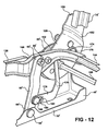
- Figure 12 is a fragmentary, enlarged view of the seat assembly of Figure 9 illustrating one of the drive links;
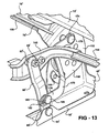
- Figure 13 is a fragmentary, enlarged view of the seat assembly of Figure 10 illustrating one of the drive links;
- Figure 14 is a fragmentary, enlarged view of the seat assembly of Figure 11 illustrating one of the drive links.
- Figure 15 is a fragmentary, enlarged view of the seat assembly of Figure 9 illustrating a hook and striker in an engaged position.
- a seat assembly for an automotive vehicle is generally shown at 10.
- the seat assembly 10 includes a generally horizontal seat cushion 12 for supporting a seat occupant above a floor 14 of the vehicle and a seat back 16 for supporting a back of the seat occupant.
- the seat assembly 10 extends laterally between an inboard side 18 and an outboard side 20.
- the seat back 16 is operatively coupled to the seat cushion 12 and pivots between a generally upright position, as shown in Figure 1 , and a folded position overlying the seat cushion 12, as shown in Figures 3 and 4 .
- the seat assembly 10 is moveable between a seating position, as shown in Figure 1 , wherein the seat back 16 is in the upright position and the seat cushion 12 is in a raised position spaced above the floor 14, and a stowed position, as shown in Figures 3 and 4 , wherein the seat back 16 is pivoted to the folded position and the seat cushion 12 is in a lowered position lying generally along the floor 14.
- the seat cushion 12 includes a seat pan 22 having opposing top 24 and bottom 26 contoured surfaces.
- the seat pan 22 extends between a front end 28 and a rear end 30.
- the seat cushion 12 may include a perimeter frame assembly or other frame structure.
- the seat pan 22 or frame structure supports a resilient cellular foam pad encased in a decorative trim cover for added comfort and appearance.
- a pair of parallel and spaced apart elongated brackets 32, 34 is adapted to be mounted to the floor 14 by bolts or any other suitable method known to those skilled in the art.
- Each elongated bracket 32, 34 extends between a forward end 38 and a rearward end 40.
- a front cross tube 42 extends laterally between and is rotatably coupled to the respective forward end 38 of each elongated bracket 32, 34.
- a riser mechanism extends between the seat cushion 12 and the elongated brackets 32, 34 located along the floor 14.
- the riser mechanism 44 allows for movement of the seat cushion 12 between the raised position spaced above the floor 14 and the lowered position lying generally along the floor 14.
- the riser mechanism 44 includes a pair of parallel and spaced apart front legs 46, 48.
- each front leg 46, 48 extends linearly between a lower end 50 and an upper end 52.
- the lower end 50 of each front leg 46, 48 is fixedly secured to the front cross tube 42.
- the upper end 52 of each front leg 46, 48 is pivotally coupled at pivot 54 to the seat pan 22, adjacent the front end 28 thereof.
- each rear leg 56, 58 is positioned rearward of the respective front legs 46, 48.
- each rear leg 56, 58 extends linearly between a lower end 60 and an upper end 62.
- the lower end 60 of each rear leg 56, 58 is pivotally coupled at pivot 64 to the respective elongated bracket 32, 34, between the forward 38 and rearward 40 ends.
- the upper end 62 of each rear leg 56, 58 is pivotally coupled at pivot 66 to the seat pan 22, adjacent the rear end 30 thereof.
- the seat back 16 includes a seat back frame, generally indicated at 68.
- the seat back frame 68 includes a pair of spaced apart and generally parallel side members 70, 72. Each side member 70, 72 extends between a lower end 74 and an upper end 76.
- the seat back frame 68 also includes an upper cross member 78 extending between the upper ends 76 of the side members 70, 72. It is appreciated that the seat back 16 is similar to the seat cushion 12 in that the seat back frame 68 also supports a resilient cellular foam pad encased in a decorative trim cover for added comfort and appearance.
- a pair of support brackets 80, 82 is provided for pivotally supporting the seat back 16.
- Each support bracket 80, 82 extends between a lower end 84 fixedly secured to the rearward end 40 of the respective elongated bracket 32, 34 and an upper end 86. It is appreciated that alternatively the support brackets 80, 82 could be formed integrally with the rearward end 40 of the respective elongated bracket 32, 34.
- the lower end 74 of the side member 70 on the inboard side 18 of the seat back 16 is pivotally coupled to the upper end 86 of the support bracket 80.
- the lower end 74 of the side member 72 on the outboard side 20 of the seat back 16 is fixedly secured to a seat back bracket 88 which in turn is pivotally coupled to the upper end 86 of the support bracket 82.
- a rear cross tube 90 extends laterally between the inboard 18 and outboard 20 sides of the seat back 16 defining an axis A about which the seat back 16 pivots.
- the rear cross tube 90 is fixedly secured to the lower end 74 of the side member 70.
- the rear cross tube 90 is fixedly secured to the seat back bracket 88.
- a latch mechanism 92 is provided for controlling pivotal movement of the seat back 20 between the upright position and the folded position.
- the latch mechanism 92 is disposed between the seat back bracket 88 and the support bracket 82 on the outboard side 20 of the seat assembly 10.
- the latch mechanism 92 is operable between a locked state and an unlocked state by actuating a release handle (not shown). In the locked state, the latch mechanism 92 maintains the seat back 16 in the upright position. In the unlocked state, the latch mechanism 92 is released to allow the seat back 16 to pivot between the upright position and the folded position. It will be appreciated that once the seat back 16 is in the folded position the latch mechanism 92 may return to the locked state to maintain the seat back 16 in the folded position.
- a drive link assembly is operatively coupled between the seat back 16 and the seat cushion 12 for automatically moving the seat cushion 12 between the raised and lowered positions in response to pivotal movement of the seat back 16 between the upright and folded positions. More specifically, the drive link assembly 94 includes a front link 96, a drive link 98, and a rear link 100.
- the front link 96 extends linearly between a proximal end 102 fixedly secured to the middle of the front cross tube 42 and an opposite distal end 104.
- the rear link 100 extends linearly between a proximal end 106 fixedly secured to the middle of the rear cross tube 90 and an opposite distal end 108.
- the drive link 98 extends between a first end 110 and a second end 112.
- the drive link 98 has a curvature or bend between the first 110 and second 112 ends.
- the first end 110 of the drive link 98 is pivotally coupled to the distal end 104 of the front link 96 at pivot 111 and the second end 112 is pivotally coupled to the distal end 108 of the rear link 100 at pivot 113.
- the seat assembly 10 also includes a passive locking mechanism, generally shown at 114, for locking the lower end of the seat back 16 and the rear end of the seat cushion 12 together when the seat assembly 10 is in the seating position. Locking the seat back 16 and seat cushion 12 together improves the forward load carrying ability of the seat assembly 10.
- the passive locking mechanism 114 includes a pair of tube sections 116, 118 mounted to the bottom surface 26 of the seat pan 22, adjacent the rear end 30 thereof, as shown in Figures 5 and 6 .
- the passive locking mechanism 114 also includes a pair of clasp members 120, 122 extending between a proximal end 124 and a free distal end 126.
- each clasp member 120, 122 is fixedly secured to the rear cross tube 90.
- the distal end 126 of each clasp member 120, 122 includes a groove 128 for lockingly engaging one of the respective tube sections 116, 118 when the seat assembly 10 is in the seating position, as shown in Figure 5 .
- the groove 128 at the distal end 126 of each clasp member 120, 122 is released from the respective tube section 116, 118 when the seat assembly 10 is in the stowed position, as shown in Figures 3 and 4 .
- the passive locking mechanism 114 shown in the current embodiment includes the pair of tube sections 116, 118 and the pair of clasp members 120, 122, it is appreciated that one tube section and one clasp member could be used without varying from the scope of the invention.
- the seat cushion 12 In operation, starting with the seat assembly 10 in the seating position, the seat cushion 12 is supported above the floor 14 in the raised position by the front 46, 48 and rear 56, 58 legs.
- the seat back 16 is supported in the upright position by the support brackets 80, 82.
- the latch mechanism 92 is released to the unlocked state by actuating the release handle to allow the seat back 16 to pivot forwardly about the axis A toward the folded position overlying the seat cushion 12.
- the rear cross tube 90 rotates in a counterclockwise direction (when viewed from Figure 1 ) causing each clasp member 120, 122 to rotate about its proximal end 124 such that the groove 128 at the distal end 126 releases from the respective tube section 116, 118.
- the counterclockwise rotation of the rear cross tube 90 causes the rear link 100 to rotate in the counterclockwise direction, thereby pulling the drive link 98 rearward.
- the rearward movement of the drive link 98 urges the front link 96 to rotate in the counterclockwise direction causing the front cross tube 42 to rotate in the counterclockwise direction.
- the counterclockwise rotation of the front cross tube 42 causes the front legs 46, 48 to pivot forwardly about the lower ends 50.
- the pivotal movement of the front legs 46, 48 moves the upper ends 52 forwardly and downwardly which simultaneously causes the rear legs 56, 58 to pivot forwardly about pivots 64.
- the pivotal movement of the front 46, 48 and rear 56, 58 legs moves the seat pan 22, and thus the seat cushion 12, forwardly and downwardly toward the floor 14 of the vehicle.
- the drive link assembly 94 automatically moves the seat cushion 12 forwardly and downwardly until the seat cushion 12 is lying generally along the floor 14 of the vehicle and the seat assembly 10 is in the stowed position.
- the latch mechanism 92 is released to the unlocked state by actuating the release handle to allow the seat back 16 to pivot rearwardly about the axis A toward the upright position.
- the rear cross tube 90 rotates in a clockwise direction (when viewed from Figure 3 ) causing the rear link 100 to also rotate in the clockwise direction, thereby pushing the drive link 98 forward.
- the forward movement of the drive link 98 urges the front link 96 to rotate in the clockwise direction causing the front cross tube 42 to rotate in the clockwise direction.
- the clockwise rotation of the front cross tube 42 causes the front legs 46, 48 to pivot rearwardly about the respective lower ends 50.
- the pivotal movement of the front legs 46, 48 moves the upper ends 52 upwardly and rearwardly which simultaneously causes the rear legs 56, 58 to pivot rearwardly about pivots 64.
- the pivotal movement of the front 46, 48 and rear 56, 58 legs moves the seat pan 22, and thus the seat cushion 12, upwardly and rearwardly toward the raised position spaced above the floor 14 of the vehicle.
- the clockwise rotation of the rear cross tube 90 causes each clasp member 120, 122 to rotate about its proximal end 124 such that the groove 128 at the distal end 126 lockingly engages the respective tube section 116, 118.
- the drive link assembly 94 automatically moves the seat cushion 12 upwardly and rearwardly until the seat cushion 12 is in the raised position spaced above the floor 14 of the vehicle and the seat assembly 10 is in the seating position.
- the seat assembly 10' includes a headrest 130 disposed at an upper end 132 of the seat back 16'.
- the headrest 130 is internally supported by a pair of headrest posts 134, 135 that are pivotally coupled to the upper cross member 78' of the seat back frame 68'.
- the headrest 130 pivots between a use position extending longitudinally with the seat back 16', as shown in Figure 7 , and a stowed position, generally perpendicular to the seat back 16', as shown in Figure 8 .
- a cable assembly (not shown), as is well known in the art, is provided for automatically actuating the headrest 130 from the use position to the stowed position in response to pivoting the seat back 16' from the upright position to the folded position.
- a perimeter seat cushion frame 136 is disposed within and rigidly supports the seat cushion 12'.
- the seat cushion frame 136 includes a pair of generally parallel side members 138, 140.
- the side members 138, 140 are spaced apart by a front member 142 and a rear member 144 extending therebetween.
- the seat cushion frame 136 also includes intermediate members 146, 148 adapted for connecting the rear member 144 with each respective side member 138, 140. It is appreciated, however, that the intermediate members 146, 148 could be integrally formed with the respective side members 138, 140 without varying from the scope of the invention.
- the pair of elongated brackets 32', 34' extends between forward ends 38' and rearward ends 40'.
- Each support bracket 80', 82' is integrally formed at the rearward end 40' of the respective elongated bracket 32', 34'.
- each front leg 46', 48' is pivotally coupled at pivot 150 to the forward end 38' of the respective elongated bracket 32', 34'.
- the upper end 52' of each front leg 46', 48' is pivotally coupled to the front member 142 of the seat cushion frame 136.
- each rear leg 56', 58' is pivotally coupled at pivot 64' to the respective elongated bracket 32', 34', between the forward 38' and rearward 40' ends.
- the upper end 62' of each rear leg 56', 58' is pivotally coupled at pivot 66' to the respective intermediate member 146, 148 of the seat cushion frame 136.
- a pair of seat back brackets 152, 154 is provided for pivotally coupling the seat back 16' to the support brackets 80', 82'. More specifically, each seat back bracket 152, 154 extends between an upper end 156 fixedly secured to the lower end 74' of the respective side member 70', 72' of the seat back frame 68' and a lower end 158 pivotally coupled to the respective support bracket 80', 82'.
- the pivotal connection between the seat back brackets 152, 154 and the support brackets 80', 82' defines the axis A' about which the seat back 16' pivots.
- the lower end 158 of each seat back bracket 152, 154 defines an open slot or hook 160, the purpose of which is described in detail below. It is appreciated that the seat back brackets 152, 154 may be integrally formed as part of the seat back frame 68' without varying from the scope of the invention.
- a pair of recliner mechanisms 162, 164 is provided for controlling pivotal movement of the seat back 16' about the axis A' between the upright position and the folded position.
- the recliner mechanisms 162, 164 also allow the seat back 16' to recline about the axis A'.
- Each recliner mechanism 162, 164 is disposed between one of the seat back brackets 152, 154 and the respective support bracket 80', 82'.
- the recliner mechanisms 162, 164 are operable between a locked state and an unlocked state by actuating a release handle 166 mounted on the outboard side 20' of the seat assembly 10', as shown in Figure 7 .
- the recliner mechanisms 162, 164 are operatively coupled together by a cross-talk tube 168 extending therebetween such that actuating the release handle 166 will actuate the recliner mechanisms 162, 164 between the locked and unlocked states simultaneously.
- the recliner mechanisms 162, 164 maintain the seat back 16' in the upright position.
- the seat back 16' can pivot between the upright and folded positions. It will be appreciated that once the seat back 16' is in the folded position, the recliner mechanisms 162, 164 may return to the locked state to maintain the seat back 16' in the folded position.
- the seat back 16' can be reclined for occupant comfort.
- a pair of S-shaped drive links 170, 172 is operatively coupled between the seat back 16' and the seat cushion 12' for automatically moving the seat cushion 12' between the raised and lowered positions in response to pivotal movement of the seat back 16' between the upright and folded positions.
- a first end 174 of each drive link 170, 172 is pivotally coupled at pivot 176 to the respective seat back bracket 152, 154.
- a second end 178 of each drive link 170, 172 is pivotally and slidably coupled to the respective rear leg 56', 58'. More specifically, the second end 178 of each drive link 170, 172 includes a slot 180 extending between a first end 182 and a second end 184.
- a pin 186 is fixedly secured to each rear leg 56', 58', between the lower 60' and upper 62' ends, and extends laterally inward therefrom.
- Each pin 186 is pivotally and slidably disposed in the slot 180 of one of the drive links 170, 172.
- the pins 186 are disposed at the first end 182 of the slots 180, as shown in Figure 12 .
- the pins 186 are also disposed at the first end 182 of the slots 180, as shown in Figure 14 .
- a striker post 188 (only one shown) is fixedly secured to each intermediate member 146, 148 and extends laterally outward therefrom.
- the hook 160 at the lower end 158 of each seat back bracket 152, 154 engages the respective striker post 188 to provide added stability to the seat cushion 12' in the raised position.
- the seat back 16' may recline a limited amount until a closed end 190 of the hook 160 abuts the striker post 188, thereby preventing the seat back 16' from reclining any farther.
- a torsion spring 192 is provided for biasing the seat back 16' toward the folded position.
- the torsion spring 192 extends between a tab 194 fixedly secured to the support bracket 80' and a post 196 fixedly secured to the seat back bracket 152.
- the seat cushion 12' is supported above the floor 14' in the raised position by the front 46', 48' and rear 56', 58' legs.
- the seat back 16' is supported in the upright position by the support brackets 80', 82'.
- the headrest 130 is supported in the use position by the headrest posts 134, 135.
- the recliner mechanisms 162, 164 are released to the unlocked state by actuating the release handle 166.
- the headrest 130 pivots forward into the stowed position and the seat back 16' is free to pivot forwardly about the axis A' toward the folded position overlying the seat cushion 16'.
- the seat back brackets 152, 154 urge the drive links 170, 172 forward.
- the drive links 170, 172 do not exert any force on the pins 186 as the slots 180 allow the drive links 170, 172 to move relative to the pins 186.
- the pins 186 slide within the slots 180 from the first end 182 to the second end 184.
- This lost motion connection between the drive links 170, 172 and rear legs 56', 58' allows the seat back 16' to pivot forwardly without any corresponding movement of the seat cushion 12' to allow time for the hooks 160 to disengage from the striker posts 188.
- the hooks 160 are disengaged from the striker posts 188, the second end 184 of the slots 180 is engaged with the pins 186, which causes the drive links 170, 172 to urge the rear legs 56', 58' to pivot forwardly about the pivots 64'.
- the pivotal movement of the rear legs 56', 58' moves the seat cushion 12' forwardly and downwardly which simultaneously causes the front legs 46', 48' to pivot forwardly about pivots 150.
- the pivotal movement of the front 46', 48' and rear 56', 58' legs moves the seat cushion 12' forwardly and downwardly toward the floor 14'.
- a back supporting surface 198 of the seat back 16' engages a seating surface 200 of the seat cushion 12', both shown in Figure 1 , and pushes the seat cushion 12' farther downward into the lowered position.
- This additional downward push by the seat back 16' rather than the drive links 170, 172 causes the front 46', 48' and rear 56', 58' legs to pivot an additional amount such that the pins 186 bottom out against the first end 182 of the slots 180, as shown in Figure 14 .
- the drive links 170, 172 automatically move the seat cushion 12' forwardly and downwardly until the seat cushion 12' is lying generally along the floor 14' of the vehicle and the seat assembly 10' is in the stowed position.
- the recliner mechanisms 162, 164 are released to the unlocked state by actuating the release handle 166 to allow the seat back 16' to pivot rearwardly about the axis A' toward the upright position.
- the seat back brackets 152, 154 urge the drive links 170,172 rearward and because the first end 182 of the slots 180 is engaged with the pins 186, the drive links 170, 172 urge the rear legs 56', 58' to pivot rearwardly about the pivots 64'.
- the pivotal movement of the rear legs 56', 58' moves the seat cushion 12' upwardly and rearwardly which simultaneously causes the front legs 46', 48' to pivot rearwardly about pivots 150.
- the pivotal movement of the front 46', 48' and rear 56', 58' legs moves the seat cushion 12' upwardly and rearwardly toward the raised position.
- the hooks 160 engage the striker posts 188.
- the drive links 170, 172 automatically move the seat cushion 12' upwardly and rearwardly until the seat cushion 12' is spaced above the floor 14' of the vehicle and the seat assembly 10' is in the seating position.
- the headrest 130 is then manually returned to the use position.
Landscapes
- Engineering & Computer Science (AREA)
- Aviation & Aerospace Engineering (AREA)
- Transportation (AREA)
- Mechanical Engineering (AREA)
- Seats For Vehicles (AREA)
Claims (11)
- Ensemble formant siège pour supporter un occupant au-dessus d'un plancher dans un véhicule automobile, l'ensemble formant siège (10') comprenant :un coussin de siège (12') adapté à être couplé en pivotement sur le plancher (14') pour un mouvement entre une position élevée au moins partiellement espacée au-dessus du plancher (14') et une position abaissée adjacente au plancher (14') ;un dossier de siège (16') adapté à être couplé en pivotement au plancher (14') pour un mouvement entre une position dressée et une position repliée recouvrant le coussin de siège (12') ;des pieds avant (46', 48') et des pieds arrière (56', 58') couplés en pivotement entre ledit coussin de siège (12') et le plancher pour permettre un mouvement dudit coussin de siège (12') entre ladite position élevée et ladite position abaissée ; etun ensemble formant tringlerie d'entraînement fonctionnellement couplée entre le dossier de siège (16') et le coussin de siège (12') pour déplacer automatiquement le coussin de siège (12') entre la position élevée et la position abaissée en réponse à un pivotement du dossier de siège (16') entre la position dressée et la position pliée, en définissant ainsi une position assise et une position escamotée de l'ensemble formant siège,caractérisé en ce quel'ensemble formant tringlerie d'entraînement comprend au moins une tringle d'entraînement (170, 172) s'étendant entre une première extrémité couplée en pivotement au dossier de siège (16') et une seconde extrémité couplée en pivotement et en coulissement au coussin de siège (12') pour déplacer automatiquement le coussin de siège (12') entre la position élevée et la position abaissée en réponse au pivotement du dossier de siège (16') entre la position dressée et la position pliée, en définissant ainsi une position d'assise et une position escamotée de l'ensemble formant siège (10'), etla première extrémité (174) de ladite au moins une tringle d'entraînement (170, 172) est couplée en pivotement à une extrémité inférieure d'un cadre (68') du dossier de siège et une seconde extrémité (178) de ladite au moins une tringle d'entraînement (170, 172) est couplée en pivotement et en coulissement à un pied arrière (56', 58') en position adjacente à l'extrémité inférieure.
- Ensemble formant siège selon la revendication 1, dans lequel ladite au moins une tringle d'entraînement (170, 172) est généralement en forme de S et la seconde extrémité (178) inclut une fente (180) s'étendant entre une première extrémité (182) et une seconde extrémité (184) pour recevoir une broche (186) attachée de manière fixe au pied arrière (56', 58'), la fente (180) et la broche (186) assurant une liaison à course morte entre le dossier de siège (16') et le coussin de siège (12').
- Ensemble formant siège selon la revendication 1, dans lequel lesdits pieds avant (46', 48') et lesdits pieds arrière (56', 58') s'étendent entre des extrémités inférieures (60') adaptées à être couplées en pivotement au plancher et des extrémités supérieures (62') couplées en pivotement aux extrémités avant et arrière respectives dudit coussin de siège.
- Ensemble formant siège selon la revendication 3, dans lequel ledit dossier de siège (16') inclut un cadre (68') de dossier de siège couplé en pivotement à une extrémité inférieure (158) à une platine de support (80', 82') adaptée à être attachée de manière fixe au plancher (14').
- Ensemble formant siège selon la revendication 2, dans lequel ladite broche (186) est disposée à ladite première extrémité (182) de ladite fente (180) quand ledit ensemble formant siège (10') est dans ladite position assise et ladite position escamotée, et elle est disposée à ladite seconde extrémité (184) de ladite fente (180) pour déplacer ledit coussin de siège (12') depuis ladite position élevée vers ladite position abaissée.
- Ensemble formant siège selon la revendication 5, dans lequel ladite extrémité inférieure dudit cadre de dossier de siège inclut un crochet (160) pour engager sélectivement un verrou (188) attaché de manière fixe audit coussin de siège (12') pour conférer une stabilité audit coussin de siège (12') dans ladite position élevée.
- Ensemble formant siège selon la revendication 6, dans lequel ladite liaison à course morte permet une amplitude prédéterminée de mouvement pivotant dudit dossier de siège (16') depuis ladite position dressée vers ladite position repliée sans aucun mouvement correspondant dudit coussin de siège (12') pour permettre audit crochet (160) de se dégager dudit verrou.
- Ensemble formant siège selon la revendication 7, incluant un mécanisme d'inclinaison (162, 164) disposé entre ladite extrémité inférieure dudit cadre (68') du dossier de siège et ladite platine de support (80', 82'), ledit mécanisme d'inclinaison pouvant être actionné entre un état bloqué pour maintenir ledit dossier de siège (16') dans ladite position dressée et un état débloqué permettant audit dossier de siège (16') de pivoter entre ladite position dressée et ladite position repliée.
- Ensemble formant siège selon la revendication 8, incluant un ressort (192) pour solliciter ledit dossier de siège (16') vers ladite position repliée.
- Ensemble formant siège selon la revendication 9, dans lequel ledit ressort (192) est disposé entre ladite extrémité inférieure dudit cadre (68') du dossier de siège et ladite platine de support (80').
- Ensemble formant siège selon la revendication 10, incluant un appui-tête (130) fonctionnellement couplé à une extrémité supérieure dudit dossier de siège (16') pour un mouvement entre une position d'utilisation s'étendant généralement longitudinalement par rapport audit dossier de siège (16') et une position escamotée disposée généralement perpendiculaire audit dossier de siège (16') en réponse au pivotement dudit dossier de siège (16') depuis ladite position dressée vers ladite position repliée.
Applications Claiming Priority (2)
| Application Number | Priority Date | Filing Date | Title |
|---|---|---|---|
| US84954606P | 2006-10-05 | 2006-10-05 | |
| EP07815952A EP2061674B1 (fr) | 2006-10-05 | 2007-10-05 | Ensemble de siège repliable à plat à liaison d'entraînement |
Related Parent Applications (2)
| Application Number | Title | Priority Date | Filing Date |
|---|---|---|---|
| EP07815952.2 Division | 2007-10-05 | ||
| EP07815952A Division EP2061674B1 (fr) | 2006-10-05 | 2007-10-05 | Ensemble de siège repliable à plat à liaison d'entraînement |
Publications (2)
| Publication Number | Publication Date |
|---|---|
| EP2329986A1 EP2329986A1 (fr) | 2011-06-08 |
| EP2329986B1 true EP2329986B1 (fr) | 2012-08-22 |
Family
ID=39268090
Family Applications (2)
| Application Number | Title | Priority Date | Filing Date |
|---|---|---|---|
| EP07815952A Ceased EP2061674B1 (fr) | 2006-10-05 | 2007-10-05 | Ensemble de siège repliable à plat à liaison d'entraînement |
| EP11000345A Ceased EP2329986B1 (fr) | 2006-10-05 | 2007-10-05 | Ensemble formant siège pliable à plat et son entraînement |
Family Applications Before (1)
| Application Number | Title | Priority Date | Filing Date |
|---|---|---|---|
| EP07815952A Ceased EP2061674B1 (fr) | 2006-10-05 | 2007-10-05 | Ensemble de siège repliable à plat à liaison d'entraînement |
Country Status (6)
| Country | Link |
|---|---|
| US (1) | US8056954B2 (fr) |
| EP (2) | EP2061674B1 (fr) |
| KR (1) | KR101407178B1 (fr) |
| CN (1) | CN101522464B (fr) |
| CA (1) | CA2661130C (fr) |
| WO (1) | WO2008040127A1 (fr) |
Families Citing this family (28)
| Publication number | Priority date | Publication date | Assignee | Title |
|---|---|---|---|---|
| DE102010048846A1 (de) * | 2010-10-19 | 2012-04-19 | Gm Global Technology Operations Llc (N.D.Ges.D. Staates Delaware) | Kraftfahrzeug |
| CA2816555C (fr) * | 2010-11-15 | 2018-08-21 | Magna Seating Inc. | Ensemble siege instantanement escamotable a deplacement lateral automatique |
| WO2012174654A1 (fr) * | 2011-06-23 | 2012-12-27 | Magna Seating Inc. | Ensemble siège escamotable dans le plancher |
| EP2736764B8 (fr) * | 2011-07-26 | 2017-08-02 | Adient Luxembourg Holding S.à r.l. | Bâti de siège pour véhicule automobile avec deux parties latérales et un tube transversal |
| DE102011113789B4 (de) * | 2011-08-29 | 2014-04-24 | Keiper Gmbh & Co. Kg | Fahrzeugsitz, insbesondere Kraftfahrzeugsitz |
| US8757711B2 (en) * | 2012-03-20 | 2014-06-24 | GM Global Technology Operations LLC | Vehicle seat |
| US9789793B2 (en) * | 2012-12-28 | 2017-10-17 | Ts Tech Co., Ltd. | Vehicle seat |
| US9776544B2 (en) * | 2014-05-20 | 2017-10-03 | Norco Industries, Inc. | Stowable seat |
| US9855865B2 (en) | 2016-03-08 | 2018-01-02 | Honda Motor Co., Ltd. | Grip mechanism for a motor vehicle seat |
| US9855866B2 (en) | 2016-03-08 | 2018-01-02 | Honda Motor Co., Ltd. | Two piece step garnish |
| US9855862B2 (en) | 2016-03-08 | 2018-01-02 | Honda Motor Co., Ltd. | Spacer for lateral slide removable seat |
| US9855861B2 (en) | 2016-03-08 | 2018-01-02 | Honda Motor Co., Ltd. | Lateral slide removable seat |
| JP6853263B2 (ja) * | 2016-03-08 | 2021-03-31 | 本田技研工業株式会社 | 自動車の座席、構成要素、及び方法 |
| US9849808B2 (en) | 2016-03-08 | 2017-12-26 | Honda Motor Co., Ltd. | End bracket for lateral slide rail for removable seat |
| US9919623B2 (en) | 2016-03-08 | 2018-03-20 | Honda Motor Co., Ltd. | Towel bar for motor vehicle seat |
| US9919620B2 (en) | 2016-03-08 | 2018-03-20 | Honda Motor Co., Ltd. | Removable seat for a motor vehicle |
| US10005376B2 (en) | 2016-03-08 | 2018-06-26 | Honda Motor Co., Ltd. | Vehicle seat |
| US9855872B2 (en) | 2016-03-08 | 2018-01-02 | Honda Motor Co., Ltd. | Garnish cap including living hinge for a vehicle seat |
| KR101816681B1 (ko) * | 2016-07-18 | 2018-02-22 | 현대다이모스(주) | 폴딩형 구조물 록킹장치 |
| CN106627267A (zh) * | 2017-01-06 | 2017-05-10 | 麦格纳汽车技术(上海)有限公司徐汇分公司 | 一种可以往后让位的后排座椅折叠机构 |
| CN109353254B (zh) * | 2018-12-06 | 2024-04-19 | 麦格纳座椅(台州)有限公司 | 一种多方向调节的换向式汽车座椅 |
| US11772526B2 (en) * | 2021-10-04 | 2023-10-03 | Honda Motor Co., Ltd. | Vehicle seat with center service door |
| CN113787943B (zh) * | 2021-10-29 | 2023-02-21 | 宁波宝贝第一母婴用品有限公司 | 折叠机构及安全座椅 |
| CN116533839A (zh) * | 2022-01-25 | 2023-08-04 | 重庆安道拓汽车部件系统有限公司 | 可变形的座部支撑系统及汽车座椅 |
| US11752911B1 (en) | 2022-04-22 | 2023-09-12 | Faurecia Automotive Seating, Llc | Occupant support with foldable headrest |
| US12539793B2 (en) * | 2022-11-15 | 2026-02-03 | Atieva, Inc. | Vehicle seat with fold-flat position |
| CN116473375B (zh) * | 2022-12-30 | 2026-01-06 | 圣奥科技股份有限公司 | 一种可折叠座椅 |
| CN117183847A (zh) * | 2023-09-27 | 2023-12-08 | 济南双英汽车座椅有限公司 | 一种多功能、多用途的前排翻折汽车座椅 |
Family Cites Families (20)
| Publication number | Priority date | Publication date | Assignee | Title |
|---|---|---|---|---|
| DE3507894C2 (de) * | 1984-03-21 | 1986-11-06 | Daimler-Benz Ag, 7000 Stuttgart | Kraftwagensitz mit einer aus der Gebrauchslage nach vorn klappbaren Rückenlehne |
| CA2111725C (fr) * | 1993-12-18 | 1998-10-13 | Wojciech Smuk | Mecanisme permettant d'incliner et de replier des sieges d'automobiles |
| US5588707A (en) * | 1995-11-14 | 1996-12-31 | General Motors Corporation | Folding seat |
| US6113191A (en) | 1998-10-21 | 2000-09-05 | Johnson Controls Technology Company | Storable seat assembly |
| US6070934A (en) | 1999-02-01 | 2000-06-06 | Ford Motor Company | Folding seat mounting apparatus |
| US6371558B1 (en) * | 1999-10-14 | 2002-04-16 | Bertrand Faure Components Ltd. | Fold flat vehicle seat |
| CA2432585A1 (fr) * | 2000-12-20 | 2002-07-18 | Intier Automotive Inc. | Ensemble de siege muni d'un pivot de dossier de fauteuil inclinable amovible |
| CA2448588C (fr) * | 2001-05-29 | 2010-05-18 | Intier Automotive Inc. | Siege a bonne accessibilite avec verrou de plancher solidaire du dossier |
| US6688696B2 (en) * | 2002-05-09 | 2004-02-10 | Timothy J. Brush | Automatic articulating seat assembly |
| JP4105534B2 (ja) * | 2002-11-28 | 2008-06-25 | トヨタ紡織株式会社 | 車両用シート |
| DE10308685C5 (de) * | 2003-02-28 | 2010-06-10 | Keiper Gmbh & Co. Kg | Fahrzeugsitz mit Bodenstellung |
| JP2005161981A (ja) * | 2003-12-02 | 2005-06-23 | Toyota Boshoku Corp | 車両用シート |
| FR2863963B1 (fr) * | 2003-12-23 | 2006-03-03 | Renault Sas | Siege pour vehicule |
| JP2005280501A (ja) * | 2004-03-30 | 2005-10-13 | Tachi S Co Ltd | 格納シート |
| US7077463B2 (en) | 2004-04-06 | 2006-07-18 | Lear Corporation | Rear fold down cargo seat with tilt down cushion |
| FR2869269B1 (fr) | 2004-04-21 | 2008-01-18 | Faurecia Sieges Automobile | Systeme de sieges rabattables comportant des boitiers de ceinture de securite |
| JP4403953B2 (ja) * | 2004-11-18 | 2010-01-27 | トヨタ紡織株式会社 | 車両用格納式シート |
| DE102005003289B4 (de) | 2005-01-25 | 2008-07-17 | Keiper Gmbh & Co.Kg | Fahrzeugsitz mit Bodenstellung |
| CA2582892A1 (fr) * | 2006-03-28 | 2007-09-28 | Intier Automotive Inc. | Siege a pivot montant |
| JP2007313977A (ja) * | 2006-05-24 | 2007-12-06 | Toyota Motor Corp | 車両用シート |
-
2007
- 2007-10-05 CA CA2661130A patent/CA2661130C/fr not_active Expired - Fee Related
- 2007-10-05 CN CN2007800369743A patent/CN101522464B/zh not_active Expired - Fee Related
- 2007-10-05 WO PCT/CA2007/001786 patent/WO2008040127A1/fr not_active Ceased
- 2007-10-05 KR KR1020097006848A patent/KR101407178B1/ko not_active Expired - Fee Related
- 2007-10-05 EP EP07815952A patent/EP2061674B1/fr not_active Ceased
- 2007-10-05 EP EP11000345A patent/EP2329986B1/fr not_active Ceased
- 2007-10-05 US US12/444,216 patent/US8056954B2/en not_active Expired - Fee Related
Also Published As
| Publication number | Publication date |
|---|---|
| CN101522464A (zh) | 2009-09-02 |
| EP2061674B1 (fr) | 2011-06-22 |
| KR20090060425A (ko) | 2009-06-12 |
| CA2661130C (fr) | 2014-12-02 |
| KR101407178B1 (ko) | 2014-06-12 |
| US20100026033A1 (en) | 2010-02-04 |
| CN101522464B (zh) | 2012-08-29 |
| WO2008040127A1 (fr) | 2008-04-10 |
| EP2061674A4 (fr) | 2009-10-14 |
| EP2329986A1 (fr) | 2011-06-08 |
| EP2061674A1 (fr) | 2009-05-27 |
| CA2661130A1 (fr) | 2008-04-10 |
| US8056954B2 (en) | 2011-11-15 |
Similar Documents
| Publication | Publication Date | Title |
|---|---|---|
| CA2661130C (fr) | Ensemble de siege repliable a plat a liaison d'entrainement | |
| CA2448588C (fr) | Siege a bonne accessibilite avec verrou de plancher solidaire du dossier | |
| EP1948470B1 (fr) | Assemblage de siege reversible | |
| US7029063B2 (en) | Drop down stow in floor automotive vehicle seat assembly | |
| US7992913B2 (en) | Fold flat seat assembly | |
| EP3071443B1 (fr) | Siège inclinable pour berline | |
| EP2066525B1 (fr) | Ensemble de siège vertical à pied arrière rétractable | |
| US10675998B2 (en) | Stow-in-floor seat assembly with pitched easy entry position | |
| US6688666B2 (en) | Second row fold and pivot seat assembly | |
| WO2008086597A1 (fr) | Siège à une position assise et une position agenouillé | |
| CN100387458C (zh) | 带自动侧向移位的可收入底板式座椅总成 | |
| EP2252479A1 (fr) | Protection par crochet vis-à-vis d'un basculement vers l'avant pour seconde rangée | |
| CN100506600C (zh) | 可收入底板的汽车座椅总成 | |
| EP1945478B1 (fr) | Ensemble siège de rangée avant doté d'un système d'escamotage avec mouvement avant de coussin de siège | |
| KR102912943B1 (ko) | 잠금 요소를 갖는 차랑 시트 | |
| EP1361106A1 (fr) | Siège à pliage automatique | |
| EP1945477B1 (fr) | Ensemble siege de deuxieme rangee dote de systeme d'escamotage avec mouvement avant de coussin de siege | |
| EP4294669B1 (fr) | Siège de véhicule doté d'un levier de verrouillage | |
| EP1593546B1 (fr) | Dispositif d'arrimage rabattable pour ensemble siège de véhicule automobile |
Legal Events
| Date | Code | Title | Description |
|---|---|---|---|
| PUAI | Public reference made under article 153(3) epc to a published international application that has entered the european phase |
Free format text: ORIGINAL CODE: 0009012 |
|
| AC | Divisional application: reference to earlier application |
Ref document number: 2061674 Country of ref document: EP Kind code of ref document: P |
|
| AK | Designated contracting states |
Kind code of ref document: A1 Designated state(s): DE FR |
|
| 17P | Request for examination filed |
Effective date: 20111207 |
|
| GRAP | Despatch of communication of intention to grant a patent |
Free format text: ORIGINAL CODE: EPIDOSNIGR1 |
|
| GRAS | Grant fee paid |
Free format text: ORIGINAL CODE: EPIDOSNIGR3 |
|
| GRAA | (expected) grant |
Free format text: ORIGINAL CODE: 0009210 |
|
| AC | Divisional application: reference to earlier application |
Ref document number: 2061674 Country of ref document: EP Kind code of ref document: P |
|
| AK | Designated contracting states |
Kind code of ref document: B1 Designated state(s): DE FR |
|
| REG | Reference to a national code |
Ref country code: DE Ref legal event code: R096 Ref document number: 602007025041 Country of ref document: DE Effective date: 20121018 |
|
| PLBE | No opposition filed within time limit |
Free format text: ORIGINAL CODE: 0009261 |
|
| STAA | Information on the status of an ep patent application or granted ep patent |
Free format text: STATUS: NO OPPOSITION FILED WITHIN TIME LIMIT |
|
| 26N | No opposition filed |
Effective date: 20130523 |
|
| REG | Reference to a national code |
Ref country code: DE Ref legal event code: R097 Ref document number: 602007025041 Country of ref document: DE Effective date: 20130523 |
|
| REG | Reference to a national code |
Ref country code: FR Ref legal event code: PLFP Year of fee payment: 9 |
|
| REG | Reference to a national code |
Ref country code: FR Ref legal event code: PLFP Year of fee payment: 10 |
|
| REG | Reference to a national code |
Ref country code: DE Ref legal event code: R082 Ref document number: 602007025041 Country of ref document: DE Representative=s name: GLAWE DELFS MOLL PARTNERSCHAFT MBB VON PATENT-, DE |
|
| REG | Reference to a national code |
Ref country code: FR Ref legal event code: PLFP Year of fee payment: 11 |
|
| REG | Reference to a national code |
Ref country code: FR Ref legal event code: PLFP Year of fee payment: 12 |
|
| PGFP | Annual fee paid to national office [announced via postgrant information from national office to epo] |
Ref country code: FR Payment date: 20210913 Year of fee payment: 15 |
|
| PGFP | Annual fee paid to national office [announced via postgrant information from national office to epo] |
Ref country code: DE Payment date: 20210831 Year of fee payment: 15 |
|
| REG | Reference to a national code |
Ref country code: DE Ref legal event code: R119 Ref document number: 602007025041 Country of ref document: DE |
|
| P01 | Opt-out of the competence of the unified patent court (upc) registered |
Effective date: 20230516 |
|
| PG25 | Lapsed in a contracting state [announced via postgrant information from national office to epo] |
Ref country code: FR Free format text: LAPSE BECAUSE OF NON-PAYMENT OF DUE FEES Effective date: 20221031 Ref country code: DE Free format text: LAPSE BECAUSE OF NON-PAYMENT OF DUE FEES Effective date: 20230503 |