EP2329996A1 - Unité d'entraînement d'arceau de sécurité pour le logement d'un arceau de sécurité à partir d'une position de logement dans une position de renversement et système de protection contre les tonneaux pour véhicules automobiles - Google Patents
Unité d'entraînement d'arceau de sécurité pour le logement d'un arceau de sécurité à partir d'une position de logement dans une position de renversement et système de protection contre les tonneaux pour véhicules automobiles Download PDFInfo
- Publication number
- EP2329996A1 EP2329996A1 EP10178753A EP10178753A EP2329996A1 EP 2329996 A1 EP2329996 A1 EP 2329996A1 EP 10178753 A EP10178753 A EP 10178753A EP 10178753 A EP10178753 A EP 10178753A EP 2329996 A1 EP2329996 A1 EP 2329996A1
- Authority
- EP
- European Patent Office
- Prior art keywords
- rollover
- drive unit
- rollover body
- coupling region
- storage position
- Prior art date
- Legal status (The legal status is an assumption and is not a legal conclusion. Google has not performed a legal analysis and makes no representation as to the accuracy of the status listed.)
- Granted
Links
Images


Classifications
-
- B—PERFORMING OPERATIONS; TRANSPORTING
- B60—VEHICLES IN GENERAL
- B60R—VEHICLES, VEHICLE FITTINGS, OR VEHICLE PARTS, NOT OTHERWISE PROVIDED FOR
- B60R21/00—Arrangements or fittings on vehicles for protecting or preventing injuries to occupants or pedestrians in case of accidents or other traffic risks
- B60R21/02—Occupant safety arrangements or fittings, e.g. crash pads
- B60R21/13—Roll-over protection
- B60R2021/132—Roll bars for convertible vehicles
- B60R2021/134—Roll bars for convertible vehicles movable from a retracted to a protection position
- B60R2021/135—Roll bars for convertible vehicles movable from a retracted to a protection position automatically during an accident
Definitions
- the invention relates to a rollover body drive unit for shifting a rollover body from a storage position to a rollover position and a rollover protection system for motor vehicles, with an adjustable between a storage position and a rollover position rollover body and the rollover body in case of need from the storage position in the rollover position adjusting drive unit.
- Rollover protection systems are used on vehicles without a rigid roof, such as convertibles or roadsters to protect the occupants in the event of a rollover of vehicles.
- the rollover body of the rollover protection systems create a survival space for the vehicle occupants with the windshield frame.
- preloaded spring systems for sudden displacement of the rollover body from its storage position in a rollover position provide so-called pyrotechnic drive units in which the triggering of the pyrotechnic unit, for example.
- a gas generator resulting sudden pressure increase is used to the rollover body in the rollover position
- the known pyrotechnic drive units sometimes have a complex structure, which requires high manufacturing and assembly costs.
- the invention has for its object to provide a drive unit for a rollover body and a rollover protection system, which can be produced particularly cost-effective and have high reliability.
- the invention solves the problem by a rollover drive unit having the features of claim 1 and a rollover protection system having the features of claim 8.
- Advantageous developments of the invention are specified in the dependent claims.
- the rollover-body drive unit has a housing having a guide section and a drive body displaceably mounted on the guide section, which drive body can be coupled to a rollover body via a connection region.
- the housing has a pressure chamber, which is in operative connection with a gas generator, so that a triggering of the gas generator causes a sudden pressure increase in the pressure chamber.
- the drive body which is displaceably arranged with a coupling region on the guide section of the housing is driven in the housing.
- the gas expanding in the pressure chamber then displaces the drive body with the rollover body from its storage position into the rollover position.
- the coupling region of the drive body is mounted on the housing or on the guide section of the housing such that the pressure chamber is largely sealed off from the environment by the drive body.
- the guide portion ensures a linear adjustment of the drive body and so a trouble-free adjustment of an attachable to the drive body rollover body from the storage position in the rollover position.
- the area over which the pressure increase in the pressure chamber causes the drive body to accelerate can be determined by overlapping the guide section with the coupling area.
- the rollover body After the displacement of a can be arranged on the drive body rollover body from the storage position to the rollover position is greater than the degree of coverage of the guide portion with the coupling region, the rollover body undergoes a partial acceleration, ie it is not accelerated over the entire adjustment.
- the rollover drive unit according to the invention is characterized by its small space and small number of parts, which allows a particularly cost-effective production of the drive unit.
- the rollover body drive unit can be connected in a simple manner to a rollover body. To shift the rollover body in the rollover case, it is only necessary to trigger the gas generator, whereby the drive body, guided by the guide portion, is removed from the housing and thereby adjusts the rollover body.
- connection of the drive body to the housing such that an increase in the pressure in the pressure chamber leads to an adjustment of the drive body is basically arbitrary.
- the determining factor here is the arrangement and design of the coupling region and of the guide section. These are arranged coaxially to each other according to a particularly advantageous embodiment of the invention.
- This embodiment of the invention enables a particularly compact design of the rollover body drive unit, wherein at the same time a reliable guidance of the drive body can be achieved via the interaction of the coupling region with the guide portion.
- the length of the interaction region also determines the duration of action of the expanding gas on the drive body and thus in the case of an arrangement of a rollover body on the drive body, the expression of the partial acceleration of the rollover body.
- the configuration of the connecting portions of the drive body and the housing, d. H. of the coupling area and the guide section is freely selectable.
- these can be dimensioned such that, in the case of the arrangement of the drive body on the housing, they seal the pressure chamber of the housing as far as possible from the environment.
- a pressure element sealing sealing element in particular an O-ring is arranged between the coupling region and the guide portion.
- the advantageously provided coaxial arrangement of coupling region and guide section allows the use of standardized sealing elements in Form of O-rings, which allow a complementary manner, a cost-effective production of the rollover drive unit.
- About the arrangement of the O-ring at the coupling region or guide section can be determined relative to the housing in a relatively simple manner, the range of motion of the drive body in which this is accelerated due to the pressure setting in the pressure chamber after triggering the gas generator, thereby also the Is set range over which a arranged on the drive body rollover body is partially accelerated.
- a locking element is provided, which is positively located with the drive body and the housing in engagement.
- a locking element which is designed such that it releases the drive body in the event of an increase in pressure, allows a securing of the rollover body arranged on the drive body in the storage position, so that the rollover body is secured against an undesired adjustment.
- the design of the locking element can basically be chosen freely, for example, the use of simple shear bolts or spring-loaded locking bodies is conceivable, which lock the drive body to the housing.
- the locking element is formed by a arranged in a groove in the coupling region and a groove in the guide portion Runddrahtsprengring.
- a round wire snap ring can be arranged in a particularly simple and cost-effective manner on the rollover body drive unit, or the guide section and the coupling region, and thus enables a cost-effective securing of the drive body to the connecting section.
- the coupling region of the drive body is arranged within the guide section.
- the coupling region of the drive body in the event of a triggering of the gas generator in the interior of the housing, namely accelerated over the guide section.
- the guide portion aligns the drive body in the manner of a run and shoots the drive body out of the guide portion.
- a sealing element for example an O-ring
- This embodiment of the invention is characterized in addition to the particularly reliable displacement of the drive body also by their small space, which makes it possible to perform the rollover drive unit in a particularly compact design.
- the guide section and the coupling region do not have a polygonal cross-section which is basically possible, but have a cylindrical cross section, in particular being designed as a hollow cylinder.
- the drive unit is formed by a rollover drive unit having a housing having a pressure chamber with a guide portion, a drive body with a connectable to the rollover body connection portion and a slidably disposed on the guide portion coupling region and one with the pressure chamber in operative connection having stationary gas generator.
- the gas generator can be arranged in any way on the housing. For example, it is possible to inject or pour in the gas generator in the case of using a plastic housing in the housing.
- the drive body of the rollover body drive unit is connected to the rollover body such that an adjustment of the drive body causes a corresponding adjustment of the rollover body.
- the housing is set relative to the rollover body, so that it is reliably ensured that in case of triggering of the gas generator of the rollover body is adjusted due to an adjustment of the drive body in the rollover position.
- the degree of overlap of the guide section and the coupling region of the drive unit determines the extent of the partial acceleration of the rollover body whose acceleration ends when the coupling region is no longer arranged on the guide section.
- the rollover protection system according to the invention is characterized by its small space and high reliability. Due to the possibility of complete By omitting, for example, a spring preload, the rollover protection system according to the invention, in addition to lower production costs, also has a lower intrinsic weight and high functional reliability.
- the arrangement of the rollover body on the drive body is basically arbitrary. According to a particularly advantageous embodiment of the invention, however, the connecting portion of the drive body is positively connected to the rollover body, in particular screwed.
- a corresponding embodiment of the invention is characterized by its high reliability and can also be produced in a particularly simple manner. Thus, it is also possible, if necessary, to carry out an exchange of the rollover body drive unit or the rollover body in a simple manner.
- the guide portion of the rollover body drive unit is inserted into a lower end of the rollover body. Accordingly, the connection of the rollover body with the drive body in the lower region of the rollover body.
- a corresponding arrangement of the rollover drive unit can be realized in a simple manner and also allows a simple connection of the gas generator with a corresponding sensor or control unit.
- the insertability of the rollover drive unit also makes it possible to carry out the rollover protection system in a particularly compact design.
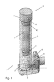
- Fig. 1 is a rollover drive unit for shifting in the Fig. 2 to 5a shown rollover body 20 from the in the Fig. 4a and 5a shown storage position in the in the Fig. 4b and 5b shown rollover position shown.
- Essential components of the rollover drive unit 1 are a housing 2, an inserted into the housing 2 drive body 3 and a projecting into the housing 2 gas generator 8.
- the drive body 3 has a cylindrically shaped coupling region 7, with which the drive body 3 within a correspondingly formed cylindrical guide portion 5 of the housing 2 is arranged.
- the drive body 3 has a connection region 6 at its end opposite the coupling region 7. This has for connection to the rollover body 20 has a threaded bore 16, so that the drive body 3 with the rollover body 20 is screwed.
- the coupling region 7 has at its end opposite the connecting region 6 a groove 13 with an O-ring 9, through which the drive body 3 is arranged gas-tight in the housing 2.
- a groove 14 is introduced into the coupling region 7, which is arranged in the inserted position of the drive body 3 in the region of a groove 15 arranged on the inside of the guide section 5.
- a round wire snap ring 10 is arranged in the mounted position on the guide portion 5 in the grooves 14,15, which cooperates with two grooves 14, 15 positively.
- the rollover body drive unit 1 has, in the region opposite the connection region 6 of the drive body 3, a pressure chamber 4, which is thus arranged between the drive body 3 and the pressure generator 8 extending into the housing 2.
- the pressure generator 8 is fixed to an opening 12 of the housing 2 by a retaining plate 11. Activation of the gas generator 8 by a sensor not shown here for a sudden pressure increase within the pressure chamber 4 as a result of the drive body 3 is suddenly transported out of the guide section 5, wherein the Pressure increase is sufficient to resolve the positive connection produced by the round wire snap ring 10.
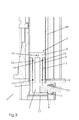
- rollover body drive unit 1 in a - based on the installation position - lower end of the rollover body 20 inserted (see also Fig. 3 ).
- the rollover body drive unit 1 is connected via a bottom plate 17 with extending from a guide cassette 21 extending struts 22, so that the rollover body drive unit 1 is fixed in position relative to the adjustable rollover body 20 and in the installed position of the rollover protection system 19 on the vehicle.
- a triggering of the gas generator 8 causes, as already stated above, a pressure increase in the pressure chamber 4, whereby the drive body 3 as a result of its existing connection with the rollover body 20 via the connecting portion 6, an adjustment of the rollover body 20 starting from the in the Fig.
Landscapes
- Engineering & Computer Science (AREA)
- Mechanical Engineering (AREA)
- Filling Or Discharging Of Gas Storage Vessels (AREA)
Priority Applications (1)
| Application Number | Priority Date | Filing Date | Title |
|---|---|---|---|
| EP20100178753 EP2329996B1 (fr) | 2010-09-23 | 2010-09-23 | Unité d'entraînement d'arceau de sécurité pour le logement d'un arceau de sécurité à partir d'une position de logement dans une position de renversement et système de protection contre les tonneaux pour véhicules automobiles |
Applications Claiming Priority (1)
| Application Number | Priority Date | Filing Date | Title |
|---|---|---|---|
| EP20100178753 EP2329996B1 (fr) | 2010-09-23 | 2010-09-23 | Unité d'entraînement d'arceau de sécurité pour le logement d'un arceau de sécurité à partir d'une position de logement dans une position de renversement et système de protection contre les tonneaux pour véhicules automobiles |
Publications (2)
| Publication Number | Publication Date |
|---|---|
| EP2329996A1 true EP2329996A1 (fr) | 2011-06-08 |
| EP2329996B1 EP2329996B1 (fr) | 2013-08-28 |
Family
ID=43569149
Family Applications (1)
| Application Number | Title | Priority Date | Filing Date |
|---|---|---|---|
| EP20100178753 Active EP2329996B1 (fr) | 2010-09-23 | 2010-09-23 | Unité d'entraînement d'arceau de sécurité pour le logement d'un arceau de sécurité à partir d'une position de logement dans une position de renversement et système de protection contre les tonneaux pour véhicules automobiles |
Country Status (1)
| Country | Link |
|---|---|
| EP (1) | EP2329996B1 (fr) |
Cited By (2)
| Publication number | Priority date | Publication date | Assignee | Title |
|---|---|---|---|---|
| DE102013100707A1 (de) | 2013-01-24 | 2014-07-24 | Benteler Automobiltechnik Gmbh | Überrollschutzsystem |
| EP2998170B1 (fr) * | 2014-09-18 | 2018-11-14 | Metalsa Automotive GmbH | Système de protection contre les tonneaux pour des véhicules automobiles |
Families Citing this family (1)
| Publication number | Priority date | Publication date | Assignee | Title |
|---|---|---|---|---|
| DE102013112266A1 (de) | 2013-11-07 | 2015-05-07 | Jakob Löwen | Überrollschutzsystem für Kraftfahrzeuge |
Citations (7)
| Publication number | Priority date | Publication date | Assignee | Title |
|---|---|---|---|---|
| EP0657326A1 (fr) * | 1993-12-13 | 1995-06-14 | ITT Automotive Europe GmbH | Arceau de sécurité pour véhicules automobiles |
| DE19501522A1 (de) * | 1994-01-29 | 1995-08-03 | Volkswagen Ag | Überrollschutzvorrichtung für eine Cabriolet |
| DE19960764A1 (de) * | 1999-12-16 | 2001-06-28 | Autoliv Dev | Pyrotechnisch angetriebener Überrollbügel für Kraftfahrzeuge |
| EP1757497A2 (fr) * | 2005-08-27 | 2007-02-28 | ISE Innomotive Systems Europe GmbH | Dispositif pyrotechnique de commande pour un moyen de retenue placé dans un véhicule automobile |
| WO2007113303A1 (fr) * | 2006-04-06 | 2007-10-11 | Ise Automotive Gmbh | dispositif de protection des personnes dans des véhicules automobiles |
| EP2006164A2 (fr) * | 2007-06-21 | 2008-12-24 | ISE Automotive GmbH | Système de protection contre les tonneaux pour véhicules automobiles dotés d'au moins un arceau de sécurité pyrotechnique pouvant être monté activement |
| EP2216209A1 (fr) * | 2009-11-13 | 2010-08-11 | ISE Automotive GmbH | Système de protection contre les tonneaux pour des véhicules automobiles |
-
2010
- 2010-09-23 EP EP20100178753 patent/EP2329996B1/fr active Active
Patent Citations (7)
| Publication number | Priority date | Publication date | Assignee | Title |
|---|---|---|---|---|
| EP0657326A1 (fr) * | 1993-12-13 | 1995-06-14 | ITT Automotive Europe GmbH | Arceau de sécurité pour véhicules automobiles |
| DE19501522A1 (de) * | 1994-01-29 | 1995-08-03 | Volkswagen Ag | Überrollschutzvorrichtung für eine Cabriolet |
| DE19960764A1 (de) * | 1999-12-16 | 2001-06-28 | Autoliv Dev | Pyrotechnisch angetriebener Überrollbügel für Kraftfahrzeuge |
| EP1757497A2 (fr) * | 2005-08-27 | 2007-02-28 | ISE Innomotive Systems Europe GmbH | Dispositif pyrotechnique de commande pour un moyen de retenue placé dans un véhicule automobile |
| WO2007113303A1 (fr) * | 2006-04-06 | 2007-10-11 | Ise Automotive Gmbh | dispositif de protection des personnes dans des véhicules automobiles |
| EP2006164A2 (fr) * | 2007-06-21 | 2008-12-24 | ISE Automotive GmbH | Système de protection contre les tonneaux pour véhicules automobiles dotés d'au moins un arceau de sécurité pyrotechnique pouvant être monté activement |
| EP2216209A1 (fr) * | 2009-11-13 | 2010-08-11 | ISE Automotive GmbH | Système de protection contre les tonneaux pour des véhicules automobiles |
Cited By (2)
| Publication number | Priority date | Publication date | Assignee | Title |
|---|---|---|---|---|
| DE102013100707A1 (de) | 2013-01-24 | 2014-07-24 | Benteler Automobiltechnik Gmbh | Überrollschutzsystem |
| EP2998170B1 (fr) * | 2014-09-18 | 2018-11-14 | Metalsa Automotive GmbH | Système de protection contre les tonneaux pour des véhicules automobiles |
Also Published As
| Publication number | Publication date |
|---|---|
| EP2329996B1 (fr) | 2013-08-28 |
Similar Documents
| Publication | Publication Date | Title |
|---|---|---|
| DE102005059910B3 (de) | Überrollschutzsystem für Kraftfahrzeuge mit einem faltbaren Überrollbügel | |
| EP2699448B1 (fr) | Dispositif de verrouillage d'un un dossier rabattable de'un siege | |
| EP1953045A2 (fr) | Système de protection contre les tonneaux pour véhicules automobiles doté d'un arceau actif de sécurité | |
| EP2329996B1 (fr) | Unité d'entraînement d'arceau de sécurité pour le logement d'un arceau de sécurité à partir d'une position de logement dans une position de renversement et système de protection contre les tonneaux pour véhicules automobiles | |
| DE102011053231B4 (de) | Längsverstelleinrichtung | |
| DE10353867B3 (de) | Überrollschutzsystem für Kraftfahrzeuge mit einem ausfahrbaren Überrollkörper | |
| EP2420413B1 (fr) | Système de protection contre les tonneaux pour des véhicules automobiles | |
| EP1227011B1 (fr) | Système d'arceau de sécurité pour véhicules automobiles | |
| EP2364884B1 (fr) | Système de protection contre les tonneaux pour des véhicules automobiles | |
| EP2340968B1 (fr) | Système de protection contre les tonneaux pour des véhicules automobiles | |
| EP2216209B1 (fr) | Système de protection contre les tonneaux pour des véhicules automobiles | |
| DE202013102125U1 (de) | Überrollkörperantriebseinheit | |
| EP1610985A1 (fr) | Dispositif de protection de personnes en cas de choc frontal avec un vehicule | |
| EP2481641B1 (fr) | Système de protection contre les tonneaux doté d'une unité d'entraînement auxiliaire | |
| EP1582420B1 (fr) | Systéme de protection pour capotage avec un arceau deployable | |
| EP2343221B1 (fr) | Système de protection contre les tonneaux pour des véhicules automobiles | |
| EP2246222B1 (fr) | Système de protection contre les tonneaux pour des véhicules automobiles | |
| DE102005028967B4 (de) | Betätigungsvorrichtung und Verfahren zum Betreiben einer Betätigungsvorrichtung | |
| DE102005028923B4 (de) | Überrollschutzsystem für ein Kraftfahrzeug, insbesondere für ein Cabriolet | |
| EP1514740B1 (fr) | Dispositif d'arceau de sécurité pour véhicules avec un arceau déployable | |
| DE10362118B4 (de) | Reversiermechanik für eine Vorrichtung zum reversiblen Aufstellen einer Fahrzeug-Tür | |
| EP2384939B1 (fr) | Système de protection contre les tonneaux pour des véhicules automobiles | |
| DE102013103204B4 (de) | Überrollschutzsystem für Kraftfahrzeuge | |
| DE102015105094A1 (de) | Überrollschutzelement | |
| EP1955907A1 (fr) | Système de protection avec arceau de sécurité pour des véhicules automobiles |
Legal Events
| Date | Code | Title | Description |
|---|---|---|---|
| PUAI | Public reference made under article 153(3) epc to a published international application that has entered the european phase |
Free format text: ORIGINAL CODE: 0009012 |
|
| AK | Designated contracting states |
Kind code of ref document: A1 Designated state(s): AL AT BE BG CH CY CZ DE DK EE ES FI FR GB GR HR HU IE IS IT LI LT LU LV MC MK MT NL NO PL PT RO SE SI SK SM TR |
|
| AX | Request for extension of the european patent |
Extension state: BA ME RS |
|
| 17P | Request for examination filed |
Effective date: 20111110 |
|
| 17Q | First examination report despatched |
Effective date: 20120809 |
|
| GRAP | Despatch of communication of intention to grant a patent |
Free format text: ORIGINAL CODE: EPIDOSNIGR1 |
|
| INTG | Intention to grant announced |
Effective date: 20130523 |
|
| GRAS | Grant fee paid |
Free format text: ORIGINAL CODE: EPIDOSNIGR3 |
|
| GRAA | (expected) grant |
Free format text: ORIGINAL CODE: 0009210 |
|
| AK | Designated contracting states |
Kind code of ref document: B1 Designated state(s): AL AT BE BG CH CY CZ DE DK EE ES FI FR GB GR HR HU IE IS IT LI LT LU LV MC MK MT NL NO PL PT RO SE SI SK SM TR |
|
| REG | Reference to a national code |
Ref country code: GB Ref legal event code: FG4D Free format text: NOT ENGLISH |
|
| REG | Reference to a national code |
Ref country code: CH Ref legal event code: EP |
|
| RAP2 | Party data changed (patent owner data changed or rights of a patent transferred) |
Owner name: METALSA AUTOMOTIVE GMBH |
|
| REG | Reference to a national code |
Ref country code: AT Ref legal event code: REF Ref document number: 629142 Country of ref document: AT Kind code of ref document: T Effective date: 20130915 |
|
| REG | Reference to a national code |
Ref country code: IE Ref legal event code: FG4D Free format text: LANGUAGE OF EP DOCUMENT: GERMAN |
|
| REG | Reference to a national code |
Ref country code: DE Ref legal event code: R096 Ref document number: 502010004493 Country of ref document: DE Effective date: 20131024 |
|
| REG | Reference to a national code |
Ref country code: AT Ref legal event code: HC Ref document number: 629142 Country of ref document: AT Kind code of ref document: T Owner name: METALSA AUTOMOTIVE GMBH, DE Effective date: 20130919 |
|
| REG | Reference to a national code |
Ref country code: LT Ref legal event code: MG4D |
|
| REG | Reference to a national code |
Ref country code: NL Ref legal event code: VDEP Effective date: 20130828 |
|
| PG25 | Lapsed in a contracting state [announced via postgrant information from national office to epo] |
Ref country code: PT Free format text: LAPSE BECAUSE OF FAILURE TO SUBMIT A TRANSLATION OF THE DESCRIPTION OR TO PAY THE FEE WITHIN THE PRESCRIBED TIME-LIMIT Effective date: 20131230 Ref country code: NO Free format text: LAPSE BECAUSE OF FAILURE TO SUBMIT A TRANSLATION OF THE DESCRIPTION OR TO PAY THE FEE WITHIN THE PRESCRIBED TIME-LIMIT Effective date: 20131128 Ref country code: CY Free format text: LAPSE BECAUSE OF FAILURE TO SUBMIT A TRANSLATION OF THE DESCRIPTION OR TO PAY THE FEE WITHIN THE PRESCRIBED TIME-LIMIT Effective date: 20130717 Ref country code: SE Free format text: LAPSE BECAUSE OF FAILURE TO SUBMIT A TRANSLATION OF THE DESCRIPTION OR TO PAY THE FEE WITHIN THE PRESCRIBED TIME-LIMIT Effective date: 20130828 Ref country code: HR Free format text: LAPSE BECAUSE OF FAILURE TO SUBMIT A TRANSLATION OF THE DESCRIPTION OR TO PAY THE FEE WITHIN THE PRESCRIBED TIME-LIMIT Effective date: 20130828 Ref country code: IS Free format text: LAPSE BECAUSE OF FAILURE TO SUBMIT A TRANSLATION OF THE DESCRIPTION OR TO PAY THE FEE WITHIN THE PRESCRIBED TIME-LIMIT Effective date: 20131228 Ref country code: LT Free format text: LAPSE BECAUSE OF FAILURE TO SUBMIT A TRANSLATION OF THE DESCRIPTION OR TO PAY THE FEE WITHIN THE PRESCRIBED TIME-LIMIT Effective date: 20130828 |
|
| REG | Reference to a national code |
Ref country code: NL Ref legal event code: VDEP Effective date: 20130828 |
|
| PG25 | Lapsed in a contracting state [announced via postgrant information from national office to epo] |
Ref country code: SI Free format text: LAPSE BECAUSE OF FAILURE TO SUBMIT A TRANSLATION OF THE DESCRIPTION OR TO PAY THE FEE WITHIN THE PRESCRIBED TIME-LIMIT Effective date: 20130828 Ref country code: PL Free format text: LAPSE BECAUSE OF FAILURE TO SUBMIT A TRANSLATION OF THE DESCRIPTION OR TO PAY THE FEE WITHIN THE PRESCRIBED TIME-LIMIT Effective date: 20130828 Ref country code: GR Free format text: LAPSE BECAUSE OF FAILURE TO SUBMIT A TRANSLATION OF THE DESCRIPTION OR TO PAY THE FEE WITHIN THE PRESCRIBED TIME-LIMIT Effective date: 20131129 Ref country code: FI Free format text: LAPSE BECAUSE OF FAILURE TO SUBMIT A TRANSLATION OF THE DESCRIPTION OR TO PAY THE FEE WITHIN THE PRESCRIBED TIME-LIMIT Effective date: 20130828 Ref country code: LV Free format text: LAPSE BECAUSE OF FAILURE TO SUBMIT A TRANSLATION OF THE DESCRIPTION OR TO PAY THE FEE WITHIN THE PRESCRIBED TIME-LIMIT Effective date: 20130828 |
|
| BERE | Be: lapsed |
Owner name: ISE AUTOMOTIVE G.M.B.H. Effective date: 20130930 |
|
| PG25 | Lapsed in a contracting state [announced via postgrant information from national office to epo] |
Ref country code: CY Free format text: LAPSE BECAUSE OF FAILURE TO SUBMIT A TRANSLATION OF THE DESCRIPTION OR TO PAY THE FEE WITHIN THE PRESCRIBED TIME-LIMIT Effective date: 20130828 |
|
| PG25 | Lapsed in a contracting state [announced via postgrant information from national office to epo] |
Ref country code: RO Free format text: LAPSE BECAUSE OF FAILURE TO SUBMIT A TRANSLATION OF THE DESCRIPTION OR TO PAY THE FEE WITHIN THE PRESCRIBED TIME-LIMIT Effective date: 20130828 Ref country code: SK Free format text: LAPSE BECAUSE OF FAILURE TO SUBMIT A TRANSLATION OF THE DESCRIPTION OR TO PAY THE FEE WITHIN THE PRESCRIBED TIME-LIMIT Effective date: 20130828 Ref country code: DK Free format text: LAPSE BECAUSE OF FAILURE TO SUBMIT A TRANSLATION OF THE DESCRIPTION OR TO PAY THE FEE WITHIN THE PRESCRIBED TIME-LIMIT Effective date: 20130828 Ref country code: EE Free format text: LAPSE BECAUSE OF FAILURE TO SUBMIT A TRANSLATION OF THE DESCRIPTION OR TO PAY THE FEE WITHIN THE PRESCRIBED TIME-LIMIT Effective date: 20130828 Ref country code: CZ Free format text: LAPSE BECAUSE OF FAILURE TO SUBMIT A TRANSLATION OF THE DESCRIPTION OR TO PAY THE FEE WITHIN THE PRESCRIBED TIME-LIMIT Effective date: 20130828 Ref country code: NL Free format text: LAPSE BECAUSE OF FAILURE TO SUBMIT A TRANSLATION OF THE DESCRIPTION OR TO PAY THE FEE WITHIN THE PRESCRIBED TIME-LIMIT Effective date: 20130828 |
|
| PG25 | Lapsed in a contracting state [announced via postgrant information from national office to epo] |
Ref country code: MC Free format text: LAPSE BECAUSE OF FAILURE TO SUBMIT A TRANSLATION OF THE DESCRIPTION OR TO PAY THE FEE WITHIN THE PRESCRIBED TIME-LIMIT Effective date: 20130828 Ref country code: IT Free format text: LAPSE BECAUSE OF FAILURE TO SUBMIT A TRANSLATION OF THE DESCRIPTION OR TO PAY THE FEE WITHIN THE PRESCRIBED TIME-LIMIT Effective date: 20130828 Ref country code: ES Free format text: LAPSE BECAUSE OF FAILURE TO SUBMIT A TRANSLATION OF THE DESCRIPTION OR TO PAY THE FEE WITHIN THE PRESCRIBED TIME-LIMIT Effective date: 20130828 |
|
| REG | Reference to a national code |
Ref country code: DE Ref legal event code: R097 Ref document number: 502010004493 Country of ref document: DE |
|
| REG | Reference to a national code |
Ref country code: IE Ref legal event code: MM4A |
|
| PLBE | No opposition filed within time limit |
Free format text: ORIGINAL CODE: 0009261 |
|
| STAA | Information on the status of an ep patent application or granted ep patent |
Free format text: STATUS: NO OPPOSITION FILED WITHIN TIME LIMIT |
|
| PG25 | Lapsed in a contracting state [announced via postgrant information from national office to epo] |
Ref country code: IE Free format text: LAPSE BECAUSE OF NON-PAYMENT OF DUE FEES Effective date: 20130923 Ref country code: BE Free format text: LAPSE BECAUSE OF NON-PAYMENT OF DUE FEES Effective date: 20130930 |
|
| 26N | No opposition filed |
Effective date: 20140530 |
|
| REG | Reference to a national code |
Ref country code: FR Ref legal event code: ST Effective date: 20140709 |
|
| REG | Reference to a national code |
Ref country code: DE Ref legal event code: R097 Ref document number: 502010004493 Country of ref document: DE Effective date: 20140530 |
|
| PG25 | Lapsed in a contracting state [announced via postgrant information from national office to epo] |
Ref country code: FR Free format text: LAPSE BECAUSE OF NON-PAYMENT OF DUE FEES Effective date: 20131028 |
|
| REG | Reference to a national code |
Ref country code: DE Ref legal event code: R082 Ref document number: 502010004493 Country of ref document: DE Representative=s name: REBBEREH, CORNELIA, DIPL.-ING., DE |
|
| REG | Reference to a national code |
Ref country code: CH Ref legal event code: PL |
|
| GBPC | Gb: european patent ceased through non-payment of renewal fee |
Effective date: 20140923 |
|
| PG25 | Lapsed in a contracting state [announced via postgrant information from national office to epo] |
Ref country code: SM Free format text: LAPSE BECAUSE OF FAILURE TO SUBMIT A TRANSLATION OF THE DESCRIPTION OR TO PAY THE FEE WITHIN THE PRESCRIBED TIME-LIMIT Effective date: 20130828 |
|
| PG25 | Lapsed in a contracting state [announced via postgrant information from national office to epo] |
Ref country code: MT Free format text: LAPSE BECAUSE OF FAILURE TO SUBMIT A TRANSLATION OF THE DESCRIPTION OR TO PAY THE FEE WITHIN THE PRESCRIBED TIME-LIMIT Effective date: 20130828 Ref country code: TR Free format text: LAPSE BECAUSE OF FAILURE TO SUBMIT A TRANSLATION OF THE DESCRIPTION OR TO PAY THE FEE WITHIN THE PRESCRIBED TIME-LIMIT Effective date: 20130828 |
|
| PG25 | Lapsed in a contracting state [announced via postgrant information from national office to epo] |
Ref country code: LU Free format text: LAPSE BECAUSE OF NON-PAYMENT OF DUE FEES Effective date: 20130923 Ref country code: GB Free format text: LAPSE BECAUSE OF NON-PAYMENT OF DUE FEES Effective date: 20140923 Ref country code: MK Free format text: LAPSE BECAUSE OF FAILURE TO SUBMIT A TRANSLATION OF THE DESCRIPTION OR TO PAY THE FEE WITHIN THE PRESCRIBED TIME-LIMIT Effective date: 20130828 Ref country code: HU Free format text: LAPSE BECAUSE OF FAILURE TO SUBMIT A TRANSLATION OF THE DESCRIPTION OR TO PAY THE FEE WITHIN THE PRESCRIBED TIME-LIMIT; INVALID AB INITIO Effective date: 20100923 Ref country code: LI Free format text: LAPSE BECAUSE OF NON-PAYMENT OF DUE FEES Effective date: 20140930 Ref country code: BG Free format text: LAPSE BECAUSE OF FAILURE TO SUBMIT A TRANSLATION OF THE DESCRIPTION OR TO PAY THE FEE WITHIN THE PRESCRIBED TIME-LIMIT Effective date: 20130828 Ref country code: CH Free format text: LAPSE BECAUSE OF NON-PAYMENT OF DUE FEES Effective date: 20140930 |
|
| REG | Reference to a national code |
Ref country code: AT Ref legal event code: MM01 Ref document number: 629142 Country of ref document: AT Kind code of ref document: T Effective date: 20150923 |
|
| PG25 | Lapsed in a contracting state [announced via postgrant information from national office to epo] |
Ref country code: AT Free format text: LAPSE BECAUSE OF NON-PAYMENT OF DUE FEES Effective date: 20150923 |
|
| PG25 | Lapsed in a contracting state [announced via postgrant information from national office to epo] |
Ref country code: AL Free format text: LAPSE BECAUSE OF FAILURE TO SUBMIT A TRANSLATION OF THE DESCRIPTION OR TO PAY THE FEE WITHIN THE PRESCRIBED TIME-LIMIT Effective date: 20130828 |
|
| P01 | Opt-out of the competence of the unified patent court (upc) registered |
Effective date: 20230531 |
|
| PGFP | Annual fee paid to national office [announced via postgrant information from national office to epo] |
Ref country code: DE Payment date: 20250904 Year of fee payment: 16 |