EP2329997B1 - Dispositif de sécurité - Google Patents
Dispositif de sécurité Download PDFInfo
- Publication number
- EP2329997B1 EP2329997B1 EP09178078.3A EP09178078A EP2329997B1 EP 2329997 B1 EP2329997 B1 EP 2329997B1 EP 09178078 A EP09178078 A EP 09178078A EP 2329997 B1 EP2329997 B1 EP 2329997B1
- Authority
- EP
- European Patent Office
- Prior art keywords
- support member
- hood
- edge
- safety device
- movement element
- Prior art date
- Legal status (The legal status is an assumption and is not a legal conclusion. Google has not performed a legal analysis and makes no representation as to the accuracy of the status listed.)
- Not-in-force
Links
- 230000000717 retained effect Effects 0.000 claims description 4
- 230000001419 dependent effect Effects 0.000 claims 1
- 230000004913 activation Effects 0.000 description 9
- 230000002441 reversible effect Effects 0.000 description 2
- 208000027418 Wounds and injury Diseases 0.000 description 1
- 230000001133 acceleration Effects 0.000 description 1
- 230000003213 activating effect Effects 0.000 description 1
- 230000003466 anti-cipated effect Effects 0.000 description 1
- 238000013459 approach Methods 0.000 description 1
- 230000000903 blocking effect Effects 0.000 description 1
- 230000006378 damage Effects 0.000 description 1
- 230000000694 effects Effects 0.000 description 1
- 208000014674 injury Diseases 0.000 description 1
- 238000000034 method Methods 0.000 description 1
- 239000003973 paint Substances 0.000 description 1
- 238000012358 sourcing Methods 0.000 description 1
Images


Classifications
-
- B—PERFORMING OPERATIONS; TRANSPORTING
- B60—VEHICLES IN GENERAL
- B60R—VEHICLES, VEHICLE FITTINGS, OR VEHICLE PARTS, NOT OTHERWISE PROVIDED FOR
- B60R21/00—Arrangements or fittings on vehicles for protecting or preventing injuries to occupants or pedestrians in case of accidents or other traffic risks
- B60R21/34—Protecting non-occupants of a vehicle, e.g. pedestrians
- B60R21/38—Protecting non-occupants of a vehicle, e.g. pedestrians using means for lifting bonnets
Definitions
- THE PRESENT INVENTION relates to a safety device, and more particularly relates to a safety device to lift the hood or bonnet of a vehicle in the event that the vehicle is involved in a crash situation.
- a prior proposed hood lifting arrangement incorporates a hinge device which allows the hood to be opened normally to allow access to the engine.
- the device also allows the rear part of the hood to be lifted by a drive means in a crash situation.
- the drive means is mounted to part of the vehicle beneath the hood. Upon activation, the drive means exerts an upward force on the underside of the hood which causes a pin in the hinge device to shear to allow the rear part of the hood to be lifted to a raised position.
- the prior proposed arrangement requires special mountings to be provided on the vehicle to mount the drive means and the hinge device to the vehicle.
- the arrangement is therefore limited for use only with vehicles which have been provided with these special mountings.
- the shear pin in the prior proposed arrangement must be replaced after the arrangement has been activated in order to reset the arrangement to its normal condition. Sourcing and fitting a replacement shear pin adds to the cost of repairing the vehicle.
- the present invention seeks to provide an improved hood-lifting safety device for use in a vehicle.
- a hood-lifting safety device for use in a vehicle, the device comprising a first elongate support member which is mounted, in use, to part of a vehicle, a second elongate support member which incorporates a mounting edge which is mounted, in use, to the hood of a vehicle, the first and second support members being attached to each other pivotally, and a movement element which is configured to be driven in a drive direction, wherein the second support member is provided with a primary elongate guide edge which extends at least partly along the second support member, the primary guide edge being inclined at an angle relative to the drive direction with the primary guide edge sloping away from the mounting edge in the drive direction, wherein the first support member incorporates a reference edge which is adjacent to and substantially parallel with the mounting edge of the second support member when the second support member is an initial position, and wherein the first support member is provided with a secondary elongate guide edge which is inclined an angle relative to the drive direction with the secondary guide edge s
- the device further comprises a drive means which is mounted to the first support member.
- first and second support members are attached to each another pivotally at or near one end and the drive means is mounted pivotally at or near the other end of the first support member by a pivot member.
- the device incorporates a mounting bracket which is attached, in use, to part of a vehicle, the mounting bracket being attached pivotally to the first support member by the pivot member.
- the primary guide edge has a groove at one end which receives and retains the movement element when the second support member is in the activated position.
- the drive means incorporates a resilient element which biases the drive means to move the movement element in a direction which is opposite to the drive direction when the movement element is retained in the groove.
- the primary guide edge is substantially straight. In a yet further embodiment, the primary guide edge is curved.
- the primary guide edge is an edge of an elongate slot which is provided in the second support member.
- the secondary guide edge is substantially straight. In another embodiment, the secondary guide edge is curved.
- the secondary guide edge is an edge of an elongate guide slot which is provided in the first support member.
- the width of the guide slot in the first support member tapers inwardly along the length of the guide slot.
- the movement element is provided with at least one bushing which is rotatably mounted to the movement element.
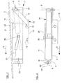
- a safety device 1 is shown mounted in position beneath the rear part of a hood 2 of a vehicle (not shown).
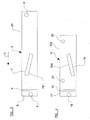
- the safety device 1 incorporates a first support member 3 which is shown on its own in figure 3 .
- the first support member 3 is a generally planar elongate rectangular element. The upper edge of the first support member 3 defines a reference edge 3a.
- the first support member 3 incorporates an angled section 4 at one end which is defined by a section of the first support member 3 which is bent at an angle which is transverse to the plane of the first support member 3.
- a planar attachment flange 5 extends from the end of the transverse section 4 in a plane which is parallel to the plane of the first support member 3.
- the attachment flange 5 incorporates a mounting aperture 6.
- the first support member 3 incorporates an elongate guide slot 7 which is formed in the planar region of the first support member 3.
- the guide slot 7 is shown to be a generally rectangular slot, but it is to be appreciated that the ends of the guide slot 7 may be rounded. In this preferred embodiment, the guide slot 7 is straight but, as will be discussed below, in other embodiments the guide slot 7 may be curved.
- the guide slot 7 extends along the first support member 3 at an inclined angle to the longitudinal axis of the first support member 3. As the guide slot 7 extends along the length of the first support member 3 from the rear part of the hood 2 towards the front part of the hood 2, the guide slot 7 slopes upwardly towards the plane of the hood 2 and towards the reference edge 3a.
- the lower edge of the guide slot 7 in the first support member 3 defines a secondary guide edge 7a.
- the purpose of the secondary guide edge 7a will become clear from the description below.
- a mounting aperture 8 is provided through the end of the first support member 3 which is remote from the end which incorporates the attachment flange 5.
- a generally cylindrical pivot member 9 extends through the mounting aperture 8 and through a further mounting aperture 10 which is provided through the end of a mounting arm 11 of a mounting bracket 12.
- a planar base 13 extends from the other end of the arm 11. The planar base 13 is provided with apertures which receive bolts 14 to attach the bracket 12 to part of a vehicle.
- the lifting device 1 incorporates a second support member 15 which is shown on its own in figure 4 .
- the second support member 15 is of the same general shape, but is shorter in length than the first support member 3.
- the second support member 15 incorporates an angled section 16 and an attachment flange 17.
- the attachment flange 17 is provided with an attachment aperture 18.
- An elongate guide slot 19 is formed in the planar section of the second support member 15.
- the guide slot 19 is shown to be a generally rectangular slot, but it is to be appreciated that the ends of the guide slot 19 may be rounded. In this preferred embodiment, the guide slot 19 is straight but, as will be discussed below, in other embodiments the guide slot 19 may be curved.
- the guide slot 19 in the second support member 15 preferably has the same travel length as the guide slot 7 in the first support member 3.
- the upper edge of the guide slot 19 in the second support member 15 defines a primary guide edge 19a.
- the purpose of the primary guide edge 19a will become clear from the description below.
- the second support member 15 incorporates two spaced apart mounting apertures 20 which are formed through an upper part of the planar section of the second support member 15.
- the mounting apertures 20 receive bolts 21 to allow the second support member 15 to be mounted to a mounting flange 21 which is provided on the underside of a rear part of the hood 2.
- the upper edge of the second support member 15 which is mounted closest to the hood 2 defines a mounting edge 15a.
- the mounting edge 15a is positioned at the top of the device 1 when the device 1 is installed in a vehicle.
- the guide slot 19 extends along the second support member 15 at an inclined angle to the longitudinal axis of the second support member 15.
- the angle of the guide slot 19 is inclined in an opposite direction to the angle of inclination of the guide slot 7 in the first support member 3, when the support members 3,15 are aligned with one another, as shown in figure 1 .
- the guide slot 19 is angled so that as the guide slot 19 extends along the length of the second support member 15 in the direction from the rear part of the hood 2 towards the front part of the hood 2, the guide slot 19 slopes downwardly, away from the plane of the hood 2 and away from the mounting edge 15a.
- a pivot shaft 23 extends through the aperture 6 in the first support member 3 and the attachment aperture 18 in the second support member 15 to attach the support members 3,15 to one another pivotally at one end.
- the planar sections of the support members 3,15 are adjacent one another with a space between them due to the angled sections 4,16, as shown in figure 2 .
- the reference edge 3a of the first support member 3 is adjacent to and substantially parallel with the mounting edge 15a of the second support member 15.
- the device 1 incorporates a drive means 24 which, in this preferred embodiment, is a piston and cylinder arrangement.
- the piston and cylinder arrangement is configured to be driven by a source of compressed gas.
- the drive means 24 incorporates the source of compressed gas.
- the drive means 24 is an electrically driven device such as an electric motor.
- the drive means 24 is mounted pivotally to the first support member 3 by the pivot element 9.
- a piston 25 protrudes outwardly from the other end of the drive means 24.
- the drive means 24 is configured to drive the piston 25 outwardly from the cylinder along a substantially straight drive axis in a drive direction towards the front of the vehicle, as indicated generally by arrow D in figure 1 .
- the primary guide edge 19a and the secondary guide edge 7a are inclined at an angle to the drive direction D.
- the drive means 24 is configured to be activated by a control arrangement (not shown) in the event that the control arrangement senses that the vehicle has been involved in a crash situation.
- the control arrangement could, for instance, incorporate an acceleration sensor which is positioned near the front of the vehicle to detect if the vehicle crashes into a pedestrian.
- the control arrangement incorporates a sensor, such as a radar or camera, which is configured to sense when a crash situation is about to occur.
- the control arrangement processes signals from the sensor and transmits an activation signal to the drive means 24 to activate the drive means 24 in the event of a crash situation, or in the event of an anticipated crash situation.
- a movement element 26 is attached pivotally to the end of the piston 25.
- the movement element 26, in this preferred embodiment, is an elongate bar with enlarged ends which extends across the width of the device 1.
- the ends of the movement element 26 extend through the guide slots 7,19 in the support members 3,15.
- the main shaft of the movement element 26 is slightly narrower than the width of the guide slots 7,19 so that the movement element 26 can slide along the slots 7,19.
- the piston 25 When the drive means 24 is in an initial, unactivated condition the piston 25 is retracted and the movement element 26 is positioned at the rightmost end of both of the guide slots 7,19, as shown in figure 1 .
- the movement element 26 engages the primary and secondary guide edges 7a,19a of the guide slots 7,19, thereby blocking the first and second support members 3,15 from pivoting relative to one another about the pivot shaft 23.
- the movement element 26 therefore locks the support members 3,15 relative to one another in the initial position, as shown in figure 1 .
- the guide slots 7,19 define elongate windows in the support members 3,15 which are aligned at one end when the device is in the normal, unactivated, condition.
- the movement element 26 is received within the aligned ends of the guide slots 7,19.
- the intersecting primary and secondary guide edges 7a,19a block movement of the first and second support members 3,15 relative to the movement element 26 to prevent the support members 3,15 from pivoting relative to one another when the device 1 is in the normal, unactivated condition.
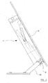
- the device 1 is, however, still free to pivot about the pivot member 9, to allow the front of the hood to be raised to provide access to the engine, as shown in figure 5 .
- the device 1 therefore allows the hood 2 to be opened manually from the front without activating of the device 1.
- the drive means 24 moves the piston 25.
- the piston 25 drives the movement element 26 in the drive direction D against the primary guide edge 7a of the guide slot 7 in the first support member 3 and against the secondary guide edge 19a of the guide slot 19 in the second support member 15.
- the movement element 26 slides along the guide slots 7,19 as it is driven by the drive means 24.
- the movement element 26 exerts a force slidably along at least part of the length of the primary and secondary guide edges 7a,19a when the movement element 26 is driven by the drive means 24.
- the movement element 26 moves along the guide slots 7,19, the movement element 26 causes the second support member 15 to pivot relative to the first support member 3 about the pivot shaft 23.
- the drive means 24 pivots about the pivot member 9 as the movement element 26 follows the path which is set by the primary and secondary guide edges 7a,19a of the guide slots 7,19.
- the movement element 26 slides along the guide slots 7,19 until the movement element 26 is blocked from moving further by the leftmost ends of the guide slots 7,19.
- the guide slots 7,19 preferably have the same travel length to avoid high friction and skewing in the drive means 24 as the drive means 24 drives the movement element 26 along the guide slots 7,19.
- the movement element 26 When the movement element 26 is at the leftmost end of the guide slots 7,19 the movement element 26 is retained in position by the edges of the guide slots 7,19 and the piston 25 so that the rear part of the hood 2 remains in the lifted position.
- the hood 2 is thus locked in the lifted position to allow a pedestrian who lands on the hood during the crash situation to deform the hood 2 over a distance, thereby cushioning the impact with the pedestrian.
- the piston 25 can be pushed back into the cylinder of the drive means 24 so that the movement element 26 slides towards the rightmost end of the guide slots 7,19, thereby allowing the second support member 15 to pivot back to the normal, unactivated position as shown in figure 1 .
- the drive means 24 is driven by gas from a cylinder. After activation, the cylinder can be refilled with compressed gas to recharge the lifting device 1.
- the drive means 24 is a reversible drive means which is configured to retract the piston 25 automatically to lower the rear part of the hood 1 to return the lifting device 1 to the normal, unactivated condition. It is particularly advantageous to provide a reversible drive means in embodiments which incorporate a sensor to sense when a crash situation might be about to occur, so that the drive means can return the hood to the normal position if the crash situation does not in fact occur.
- a further embodiment of the invention incorporates a central collar which is fixed to the end of the piston 25.
- the collar 27 receives the movement element 26 rotatably so that the movement element 26 can rotate within the collar 27.
- Hollow cylindrical bushings 28,29 are provided on either side of the collar 27 around the ends of the movement element 26.
- the bushings 28,29 are configured to rotate around the ends of the movement element 26.
- the bushings 28,29 are dimensioned to fit slidably in the respective guide slots 7,19.
- the bushings 28,29 rotate as the movement element 26 moves along the guide slots 7,19 to facilitate movement of the movement element 26 and to minimise friction against the edges of the guide slots 7,19.
- a yet further embodiment of the invention is identical to the preferred embodiment described above, except that this yet further embodiment incorporates curved guide slots 7,19.
- the guide slot 7 in the first support member 3 curves in an arc upwardly in the drive direction D.
- the guide slot 19 in the second support member 15 curves in the same arcuate shape as the guide slot 7 in the first support member 3 in the drive direction D.
- the curvature of the guide slots 7,19 causes the device 1 to lift the rear part of the hood 2 slowly at first and then more quickly as the device 1 moves towards the activated condition.
- the curved guide slots 7,19 shown in figure 8 are both inverted so that they curve arcuately downwardly in the drive direction D. This downward curve of the guide slots 7,19 causes the device 1 to lift the rear part of the hood 2 quickly at first and then more gradually as the device 1 moves towards the activated condition.
- the guide slots 7,19 curve in opposite directions, that is to say, with one of the guide slots 7,19 curving upwardly and the other guide slots 7,19 curving downwardly in the drive direction D.
- one of the guide slots 7,19 may be straight, with the other guide slots 7,19 being curved upwardly or downwardly in the drive direction D. It is to be appreciated that the way in which the lifting device 1 lifts the rear part of the hood 2 can be selected by choosing different guide slot configurations as required.
- the width of the guide slot 7 in the first support member 3 tapers inwardly in the drive direction D to a narrow end 29.
- the edges of the guide slot 7 resist movement of the movement element 26 along the tapered guide slot 7 which slows the movement of the movement element 26, and hence slows lifting of the rear part of the hood 2, as the lifting device 1 approaches the activated condition.
- the guide slot 19 in the second support member 15 is tapered instead of or in addition to the guide slot 7 in the first support member 3.
- the guide slots 7,19 are curved in a similar fashion to the embodiment shown in figure 8 .
- the guide slot 19 in the second support member 15 is provided with a substantially S-shaped groove 30 at the rightmost end of the guide slot 19 which is furthest from the drive means 24.
- the movement element 26 moves towards the front end of the guide slot 19, the movement element 26 slips downwardly into the groove 30.
- the movement element 26 is received and retained in the groove 30 to lock the lifting device 1 in the activated position, with the rear part of the hood 2 being locked in the lifted position. This may be desirable to lock the rear part of the hood 2 in the lifted position to prevent the hood 2 from lowering when a pedestrian lands on the hood 2.
- a modified drive means 31 is used in embodiments of the invention which have a groove 30 in one of the guide slots 7,19, as shown in figure 10 .
- the modified drive means 31 incorporates a resilient element, such as an internal spring 32 which is compressed by the piston 33 when the piston 33 is fully extended from the drive means 31.
- the spring 32 biases the piston 33 towards the retracted position so that the piston 33 pulls the movement element 26 out from the groove 30 of the guide slot if the rear part of the hood 2 is lifted.
- the modified drive means 31 with the spring 32 thus makes it easier to reset the device 1 after activation.
- the safety device 1 of embodiments of the invention is a hinge which incorporates an integrated drive means 24.
- the safety device 1 does not require a drive means to be mounted elsewhere in the vehicle to lift the rear part of the hood 2. Consequently, the device 1 does not require special mountings to be provided on a vehicle to mount a separate drive means.
- the device 1 can be mounted to standard mounting components provided on the underside of the hood and to a standard mounting brackets provided on a vehicle.
- the drive means 24 can be mounted to the safety device 1 after the other hinge parts of the safety device 1 have been mounted to the hood 2 and the vehicle and been painted.
- the drive means 24 is mounted between the first support member 3 and the second support member 15 and the movement element 26 exerts forces on the support members 3,15 equally in the same general direction. The drive forces of the drive means 24 are therefore equally distributed between the support member 3,15.
- the drive means 24 comprises a pyrotechnical gas generator.
- the drive means 24 is itself filled with compressed gas.
- the cylinder of the drive means 24 can be pressurised by gas at a pressure used commonly in paint ball guns. It is therefore cheap to recharge the drive means 24 after activation by simply re-pressurising the chamber with commonly available source of compressed gas.
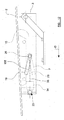
- FIG 12 of the accompanying drawings a further embodiment of the invention is similar to the preferred embodiment described above.
- the guide slots 7,19 in the support members 3,15 of this further embodiment are, however, inverted and the arrangement incorporates a modified drive means 34 which is mounted pivotally to the pivot shaft 23.
- the modified drive means 34 is an electric motor which is configured to wind in a cable 35 which is connected to the movement element 26.
- the modified drive means 34 is a retractable drive means which, when activated, pulls the movement element 26 towards the pivot shaft 23 in a drive direction D.
- the movement element 26 is pulled against the primary guide edge 19a, which is the lower elongate edge of the guide slot 19, as shown in figure 12 .
- the movement element 26 is also pulled slidably against the secondary guide edge 7a of the guide slot 7 in the first support member 3.
- the force which the movement element 26 exerts slidably along the guide edge 19a causes the first and second support members 3,15 to pivot relative to one another about the pivot shaft 23 from an initial position to an activated position.
- the modified guide means 34 is replaced with a piston and cylinder arrangement in which the piston is extended when the device is in the normal, unactivated, condition.
- the piston is retracted to pull the movement element 26 in the drive direction D.
- the modified drive means 34 is not mounted to the first or second support members 3,15, but is instead provided elsewhere on the vehicle, such as at another position on the underside of the hood 2.
- the modified drive means can be configured to pull a flexible element or cable which can be guided to an appropriate position to drive the movement element 26.
- the modified drive means can therefore be positioned away from the hinge of the hood 2.
- An advantage of embodiments of the invention is that only the drive means 24 needs to be re-charged or replaced after the safety device 1 has been activated.
- Embodiments of the invention do not incorporate a shear pin which shears during activation and which must be replaced after activation.
- the same drive means 24 can be used in different embodiments of the invention which are each adapted to be mounted to different standard vehicle hood mounts.
- the guide edges 7a,19a are defined by edges of guide slots 7,19, in other embodiments of the invention, one or both of the guide edges is defined by a different part of the support members 3,15.
- the primary guide edge is defined by the lower edge of the planar section of the secondary support member 15.
- the primary or secondary guide edges are defined by the edge of an elongate wall which protrudes from one side of the support members 3,15.
- the safety device 1 of the preferred embodiment of the invention is a hinged lifting device which has an integrated drive means 24.
- the safety device 1 of the preferred embodiment is therefore different from prior art lifting arrangements in which a hinged device and a drive means are provided separately from one another. In other embodiments, however, it is to be appreciated that the drive means may be separate to the rest of the device 1.
Landscapes
- Engineering & Computer Science (AREA)
- Mechanical Engineering (AREA)
- Superstructure Of Vehicle (AREA)
Claims (14)
- Dispositif de sécurité pour lever un capot destiné à être utilisé dans un véhicule, le dispositif comprenant :un premier élément de support (3) allongé qui est monté, lors de l'utilisation, sur une partie d'un véhicule,un second élément de support (15) allongé qui inclut un bord de montage (15a) qui est monté, lors de l'utilisation, sur le capot (2) d'un véhicule, les premier et second éléments de support (3, 15) étant fixés l'un à l'autre de manière pivotante, etun élément mobile (26) qui est configuré pour être entraîné dans une direction d'entraînement (D), caractérisé en ce que :le second élément de support (15) est doté d'un bord de guidage principal (19a) allongé, qui s'étend au moins partiellement le long du second élément de support (15), le bord de guidage principal (19a) étant incliné selon un angle par rapport à la direction d'entraînement (D) avec le bord de guidage principal (19a) s'éloignant en pente du bord de montage (15a) dans la direction d'entraînement (D), le premier élément de support (3) incluant un bord de référence (3a) qui est adjacent et essentiellement parallèle au bord de montage (15a) du second élément de support (15) quand le second élément de support (15a) est dans une position initiale, et dans lequel le premier élément de support (3) est doté d'un bord de guidage secondaire (7a) allongé, qui est incliné selon un angle par rapport à la direction d'entraînement (D) avec le bord de guidage secondaire (7) s'approchant en pente du bord de référence (3a) dans la direction d'entraînement (D), l'élément mobile (26) étant en contact avec le bord de guidage principal (19a) et le bord de guidage secondaire (7a) et exerçant une force de manière coulissante le long d'au moins une partie de la longueur du bord de guidage principal (19a) et du bord de guidage secondaire (7a) quand l'élément mobile (26) est entraîné dans la direction d'entraînement (D) pour faire pivoter le second élément de support (15) par rapport au premier élément de support (3) de la position initiale à une position activée.
- Dispositif de sécurité pour lever un capot selon la revendication 1, dans lequel le dispositif comprend en outre un moyen d'entraînement (24, 31, 34) qui est monté sur le premier élément de support (3).
- Dispositif de sécurité pour lever un capot selon la revendication 2, dans lequel les premier et second éléments de support (3, 15) sont fixés l'un à l'autre de manière pivotante sur ou près d'une extrémité et le moyen d'entraînement (24) est monté de manière pivotante sur ou près de l'autre extrémité du premier élément de support (3) par le biais d'un élément de pivotement (9).
- Dispositif de sécurité pour lever un capot selon la revendication 3, dans lequel le dispositif inclut un support de montage (12) qui est fixé, lors de l'utilisation, à une partie d'un véhicule, le support de montage (12) étant fixé de manière pivotante au premier élément de support (3) par le biais de l'élément de pivotement (9).
- Dispositif de sécurité pour lever un capot selon l'une quelconque des revendications précédentes, dans lequel le bord de guidage principal (19a) comporte une rainure (30) sur une extrémité, qui reçoit et retient l'élément mobile (26) quand le second élément de support (15) est dans la position activée.
- Dispositif de sécurité pour lever un capot selon la revendication 5 quand elle dépend de l'une quelconque des revendications 2 à 4, dans lequel le moyen d'entraînement (31) inclut un élément résilient (32) qui contraint le moyen d'entraînement (31) à déplacer l'élément mobile (26) dans une direction qui est opposée à la direction d'entraînement (D) quand l'élément mobile (26) est retenu dans la rainure (30).
- Dispositif de sécurité pour lever un capot selon l'une quelconque des revendications précédentes, dans lequel le bord de guidage principal (19a) est essentiellement droit.
- Dispositif de sécurité pour lever un capot selon l'une quelconque des revendications 1 à 6, dans lequel le bord de guidage principal (19a) est incurvé.
- Dispositif de sécurité pour lever un capot selon l'une quelconque des revendications précédentes, dans lequel le bord de guidage principal (19a) est un bord d'une fente (19) allongée qui se trouve dans le second élément de support (15).
- Dispositif de sécurité pour lever un capot selon l'une quelconque des revendications précédentes, dans lequel le bord de guidage secondaire (7a) est essentiellement droit.
- Dispositif de sécurité pour lever un capot selon l'une quelconque des revendications 1 à 9, dans lequel le bord de guidage secondaire (7a) est incurvé.
- Dispositif de sécurité pour lever un capot selon l'une quelconque des revendications précédentes, dans lequel le bord de guidage secondaire (7a) est un bord d'une fente de guidage (7) allongée qui se trouve dans le premier élément de support (3).
- Dispositif de sécurité pour lever un capot selon la revendication 12, dans lequel la largeur de la fente de guidage (7) dans le premier élément de support (3) s'amincit vers l'intérieur le long de la longueur de la fente de guidage (7).
- Dispositif de sécurité pour lever un capot selon l'une quelconque des revendications précédentes, dans lequel l'élément mobile (26) est doté d'au moins une bague (28, 29) qui est montée rotative sur l'élément mobile (26).
Priority Applications (1)
| Application Number | Priority Date | Filing Date | Title |
|---|---|---|---|
| EP09178078.3A EP2329997B1 (fr) | 2009-12-04 | 2009-12-04 | Dispositif de sécurité |
Applications Claiming Priority (1)
| Application Number | Priority Date | Filing Date | Title |
|---|---|---|---|
| EP09178078.3A EP2329997B1 (fr) | 2009-12-04 | 2009-12-04 | Dispositif de sécurité |
Publications (2)
| Publication Number | Publication Date |
|---|---|
| EP2329997A1 EP2329997A1 (fr) | 2011-06-08 |
| EP2329997B1 true EP2329997B1 (fr) | 2015-08-12 |
Family
ID=41557595
Family Applications (1)
| Application Number | Title | Priority Date | Filing Date |
|---|---|---|---|
| EP09178078.3A Not-in-force EP2329997B1 (fr) | 2009-12-04 | 2009-12-04 | Dispositif de sécurité |
Country Status (1)
| Country | Link |
|---|---|
| EP (1) | EP2329997B1 (fr) |
Families Citing this family (2)
| Publication number | Priority date | Publication date | Assignee | Title |
|---|---|---|---|---|
| EP2423056B1 (fr) * | 2010-08-25 | 2013-03-13 | Autoliv Development AB | Dispositif de sécurité |
| AT511710B1 (de) * | 2011-10-03 | 2013-02-15 | Hirtenberger Automotive Safety Gmbh & Co Kg | Vorrichtung zum anstellen einer motorhaube |
Family Cites Families (2)
| Publication number | Priority date | Publication date | Assignee | Title |
|---|---|---|---|---|
| DE10116716A1 (de) | 2001-04-04 | 2002-10-10 | Volkswagen Ag | Scharniereinrichtung für eine anhebbare Fronthaube an einem Fahrzeug |
| JP2003182511A (ja) | 2001-12-25 | 2003-07-03 | Aisin Seiki Co Ltd | 車両フード跳ね上げ装置及びその制御方法 |
-
2009
- 2009-12-04 EP EP09178078.3A patent/EP2329997B1/fr not_active Not-in-force
Also Published As
| Publication number | Publication date |
|---|---|
| EP2329997A1 (fr) | 2011-06-08 |
Similar Documents
| Publication | Publication Date | Title |
|---|---|---|
| KR101096169B1 (ko) | 보행자 보호를 위한 자동차 후드용 힌지 어셈블리 | |
| US7575273B2 (en) | Bonnet bumpstop for a vehicle | |
| EP2810832B1 (fr) | Dispositif de charnière pour liaison articulée d'un capot du châssis d'un véhicule | |
| EP3521111B1 (fr) | Agencement de charnière | |
| EP2634047B1 (fr) | Mécanisme de charnière | |
| EP1494895B1 (fr) | Dispositif de securite permettant de lever la partie arriere du capot d'un vehicule a moteur | |
| US7410027B2 (en) | Device for reducing the impact for pedestrians | |
| EP2907704B1 (fr) | Agencement comprenant un dispositif pyrotechnique et une première structure mécanique | |
| US20050279550A1 (en) | Hinge arrangement | |
| EP2495140A1 (fr) | Ensemble de charnière de capot pour véhicule à moteur | |
| WO2004074051A1 (fr) | Systeme de securite | |
| EP1615808B1 (fr) | Dispositif de securite | |
| CN117584887A (zh) | 用于车辆翻板的驱动装置 | |
| EP2329997B1 (fr) | Dispositif de sécurité | |
| EP2345563B1 (fr) | Système de capot déployable | |
| JP7527507B2 (ja) | 歩行者保護用自動車ヒンジ | |
| EP3184377B1 (fr) | Agencement de charnière | |
| EP2380787A1 (fr) | Mécanisme de charnière | |
| EP3323683B1 (fr) | Agencement de charnière | |
| EP2301814B1 (fr) | Agencement de sécurité pour véhicule | |
| EP2358569B1 (fr) | Agencement de sécurité | |
| EP2423056B1 (fr) | Dispositif de sécurité | |
| WO2011162675A1 (fr) | Dispositif de protection de piétons pour un véhicule | |
| CN108001403A (zh) | 引擎罩抬升装置和车辆 | |
| EP3184376B1 (fr) | Agencement de charnière |
Legal Events
| Date | Code | Title | Description |
|---|---|---|---|
| PUAI | Public reference made under article 153(3) epc to a published international application that has entered the european phase |
Free format text: ORIGINAL CODE: 0009012 |
|
| AK | Designated contracting states |
Kind code of ref document: A1 Designated state(s): AT BE BG CH CY CZ DE DK EE ES FI FR GB GR HR HU IE IS IT LI LT LU LV MC MK MT NL NO PL PT RO SE SI SK SM TR |
|
| AX | Request for extension of the european patent |
Extension state: AL BA RS |
|
| 17P | Request for examination filed |
Effective date: 20111208 |
|
| 17Q | First examination report despatched |
Effective date: 20120614 |
|
| GRAP | Despatch of communication of intention to grant a patent |
Free format text: ORIGINAL CODE: EPIDOSNIGR1 |
|
| INTG | Intention to grant announced |
Effective date: 20150306 |
|
| GRAS | Grant fee paid |
Free format text: ORIGINAL CODE: EPIDOSNIGR3 |
|
| GRAA | (expected) grant |
Free format text: ORIGINAL CODE: 0009210 |
|
| AK | Designated contracting states |
Kind code of ref document: B1 Designated state(s): AT BE BG CH CY CZ DE DK EE ES FI FR GB GR HR HU IE IS IT LI LT LU LV MC MK MT NL NO PL PT RO SE SI SK SM TR |
|
| REG | Reference to a national code |
Ref country code: GB Ref legal event code: FG4D |
|
| REG | Reference to a national code |
Ref country code: CH Ref legal event code: EP |
|
| REG | Reference to a national code |
Ref country code: AT Ref legal event code: REF Ref document number: 741848 Country of ref document: AT Kind code of ref document: T Effective date: 20150815 |
|
| REG | Reference to a national code |
Ref country code: IE Ref legal event code: FG4D |
|
| REG | Reference to a national code |
Ref country code: DE Ref legal event code: R096 Ref document number: 602009032780 Country of ref document: DE |
|
| REG | Reference to a national code |
Ref country code: LT Ref legal event code: MG4D |
|
| REG | Reference to a national code |
Ref country code: AT Ref legal event code: MK05 Ref document number: 741848 Country of ref document: AT Kind code of ref document: T Effective date: 20150812 |
|
| REG | Reference to a national code |
Ref country code: NL Ref legal event code: MP Effective date: 20150812 |
|
| PG25 | Lapsed in a contracting state [announced via postgrant information from national office to epo] |
Ref country code: FI Free format text: LAPSE BECAUSE OF FAILURE TO SUBMIT A TRANSLATION OF THE DESCRIPTION OR TO PAY THE FEE WITHIN THE PRESCRIBED TIME-LIMIT Effective date: 20150812 Ref country code: GR Free format text: LAPSE BECAUSE OF FAILURE TO SUBMIT A TRANSLATION OF THE DESCRIPTION OR TO PAY THE FEE WITHIN THE PRESCRIBED TIME-LIMIT Effective date: 20151113 Ref country code: LT Free format text: LAPSE BECAUSE OF FAILURE TO SUBMIT A TRANSLATION OF THE DESCRIPTION OR TO PAY THE FEE WITHIN THE PRESCRIBED TIME-LIMIT Effective date: 20150812 Ref country code: NO Free format text: LAPSE BECAUSE OF FAILURE TO SUBMIT A TRANSLATION OF THE DESCRIPTION OR TO PAY THE FEE WITHIN THE PRESCRIBED TIME-LIMIT Effective date: 20151112 Ref country code: LV Free format text: LAPSE BECAUSE OF FAILURE TO SUBMIT A TRANSLATION OF THE DESCRIPTION OR TO PAY THE FEE WITHIN THE PRESCRIBED TIME-LIMIT Effective date: 20150812 |
|
| PG25 | Lapsed in a contracting state [announced via postgrant information from national office to epo] |
Ref country code: ES Free format text: LAPSE BECAUSE OF FAILURE TO SUBMIT A TRANSLATION OF THE DESCRIPTION OR TO PAY THE FEE WITHIN THE PRESCRIBED TIME-LIMIT Effective date: 20150812 Ref country code: PT Free format text: LAPSE BECAUSE OF FAILURE TO SUBMIT A TRANSLATION OF THE DESCRIPTION OR TO PAY THE FEE WITHIN THE PRESCRIBED TIME-LIMIT Effective date: 20151214 Ref country code: PL Free format text: LAPSE BECAUSE OF FAILURE TO SUBMIT A TRANSLATION OF THE DESCRIPTION OR TO PAY THE FEE WITHIN THE PRESCRIBED TIME-LIMIT Effective date: 20150812 Ref country code: IS Free format text: LAPSE BECAUSE OF FAILURE TO SUBMIT A TRANSLATION OF THE DESCRIPTION OR TO PAY THE FEE WITHIN THE PRESCRIBED TIME-LIMIT Effective date: 20151212 Ref country code: HR Free format text: LAPSE BECAUSE OF FAILURE TO SUBMIT A TRANSLATION OF THE DESCRIPTION OR TO PAY THE FEE WITHIN THE PRESCRIBED TIME-LIMIT Effective date: 20150812 Ref country code: SE Free format text: LAPSE BECAUSE OF FAILURE TO SUBMIT A TRANSLATION OF THE DESCRIPTION OR TO PAY THE FEE WITHIN THE PRESCRIBED TIME-LIMIT Effective date: 20150812 Ref country code: AT Free format text: LAPSE BECAUSE OF FAILURE TO SUBMIT A TRANSLATION OF THE DESCRIPTION OR TO PAY THE FEE WITHIN THE PRESCRIBED TIME-LIMIT Effective date: 20150812 |
|
| PG25 | Lapsed in a contracting state [announced via postgrant information from national office to epo] |
Ref country code: NL Free format text: LAPSE BECAUSE OF FAILURE TO SUBMIT A TRANSLATION OF THE DESCRIPTION OR TO PAY THE FEE WITHIN THE PRESCRIBED TIME-LIMIT Effective date: 20150812 |
|
| PG25 | Lapsed in a contracting state [announced via postgrant information from national office to epo] |
Ref country code: CZ Free format text: LAPSE BECAUSE OF FAILURE TO SUBMIT A TRANSLATION OF THE DESCRIPTION OR TO PAY THE FEE WITHIN THE PRESCRIBED TIME-LIMIT Effective date: 20150812 Ref country code: SK Free format text: LAPSE BECAUSE OF FAILURE TO SUBMIT A TRANSLATION OF THE DESCRIPTION OR TO PAY THE FEE WITHIN THE PRESCRIBED TIME-LIMIT Effective date: 20150812 Ref country code: EE Free format text: LAPSE BECAUSE OF FAILURE TO SUBMIT A TRANSLATION OF THE DESCRIPTION OR TO PAY THE FEE WITHIN THE PRESCRIBED TIME-LIMIT Effective date: 20150812 Ref country code: DK Free format text: LAPSE BECAUSE OF FAILURE TO SUBMIT A TRANSLATION OF THE DESCRIPTION OR TO PAY THE FEE WITHIN THE PRESCRIBED TIME-LIMIT Effective date: 20150812 Ref country code: IT Free format text: LAPSE BECAUSE OF FAILURE TO SUBMIT A TRANSLATION OF THE DESCRIPTION OR TO PAY THE FEE WITHIN THE PRESCRIBED TIME-LIMIT Effective date: 20150812 |
|
| REG | Reference to a national code |
Ref country code: DE Ref legal event code: R097 Ref document number: 602009032780 Country of ref document: DE |
|
| PG25 | Lapsed in a contracting state [announced via postgrant information from national office to epo] |
Ref country code: BE Free format text: LAPSE BECAUSE OF NON-PAYMENT OF DUE FEES Effective date: 20151231 Ref country code: RO Free format text: LAPSE BECAUSE OF FAILURE TO SUBMIT A TRANSLATION OF THE DESCRIPTION OR TO PAY THE FEE WITHIN THE PRESCRIBED TIME-LIMIT Effective date: 20150812 |
|
| PLBE | No opposition filed within time limit |
Free format text: ORIGINAL CODE: 0009261 |
|
| STAA | Information on the status of an ep patent application or granted ep patent |
Free format text: STATUS: NO OPPOSITION FILED WITHIN TIME LIMIT |
|
| REG | Reference to a national code |
Ref country code: DE Ref legal event code: R119 Ref document number: 602009032780 Country of ref document: DE |
|
| 26N | No opposition filed |
Effective date: 20160513 |
|
| PG25 | Lapsed in a contracting state [announced via postgrant information from national office to epo] |
Ref country code: LU Free format text: LAPSE BECAUSE OF FAILURE TO SUBMIT A TRANSLATION OF THE DESCRIPTION OR TO PAY THE FEE WITHIN THE PRESCRIBED TIME-LIMIT Effective date: 20151204 Ref country code: MC Free format text: LAPSE BECAUSE OF FAILURE TO SUBMIT A TRANSLATION OF THE DESCRIPTION OR TO PAY THE FEE WITHIN THE PRESCRIBED TIME-LIMIT Effective date: 20150812 |
|
| REG | Reference to a national code |
Ref country code: CH Ref legal event code: PL |
|
| GBPC | Gb: european patent ceased through non-payment of renewal fee |
Effective date: 20151204 |
|
| PG25 | Lapsed in a contracting state [announced via postgrant information from national office to epo] |
Ref country code: SI Free format text: LAPSE BECAUSE OF FAILURE TO SUBMIT A TRANSLATION OF THE DESCRIPTION OR TO PAY THE FEE WITHIN THE PRESCRIBED TIME-LIMIT Effective date: 20150812 |
|
| REG | Reference to a national code |
Ref country code: IE Ref legal event code: MM4A |
|
| REG | Reference to a national code |
Ref country code: FR Ref legal event code: ST Effective date: 20160831 |
|
| PG25 | Lapsed in a contracting state [announced via postgrant information from national office to epo] |
Ref country code: GB Free format text: LAPSE BECAUSE OF NON-PAYMENT OF DUE FEES Effective date: 20151204 Ref country code: LI Free format text: LAPSE BECAUSE OF NON-PAYMENT OF DUE FEES Effective date: 20151231 Ref country code: DE Free format text: LAPSE BECAUSE OF NON-PAYMENT OF DUE FEES Effective date: 20160701 Ref country code: IE Free format text: LAPSE BECAUSE OF NON-PAYMENT OF DUE FEES Effective date: 20151204 Ref country code: CH Free format text: LAPSE BECAUSE OF NON-PAYMENT OF DUE FEES Effective date: 20151231 |
|
| PG25 | Lapsed in a contracting state [announced via postgrant information from national office to epo] |
Ref country code: FR Free format text: LAPSE BECAUSE OF NON-PAYMENT OF DUE FEES Effective date: 20151231 |
|
| PG25 | Lapsed in a contracting state [announced via postgrant information from national office to epo] |
Ref country code: BE Free format text: LAPSE BECAUSE OF FAILURE TO SUBMIT A TRANSLATION OF THE DESCRIPTION OR TO PAY THE FEE WITHIN THE PRESCRIBED TIME-LIMIT Effective date: 20150812 |
|
| PG25 | Lapsed in a contracting state [announced via postgrant information from national office to epo] |
Ref country code: SM Free format text: LAPSE BECAUSE OF FAILURE TO SUBMIT A TRANSLATION OF THE DESCRIPTION OR TO PAY THE FEE WITHIN THE PRESCRIBED TIME-LIMIT Effective date: 20150812 Ref country code: HU Free format text: LAPSE BECAUSE OF FAILURE TO SUBMIT A TRANSLATION OF THE DESCRIPTION OR TO PAY THE FEE WITHIN THE PRESCRIBED TIME-LIMIT; INVALID AB INITIO Effective date: 20091204 Ref country code: BG Free format text: LAPSE BECAUSE OF FAILURE TO SUBMIT A TRANSLATION OF THE DESCRIPTION OR TO PAY THE FEE WITHIN THE PRESCRIBED TIME-LIMIT Effective date: 20150812 |
|
| PG25 | Lapsed in a contracting state [announced via postgrant information from national office to epo] |
Ref country code: CY Free format text: LAPSE BECAUSE OF FAILURE TO SUBMIT A TRANSLATION OF THE DESCRIPTION OR TO PAY THE FEE WITHIN THE PRESCRIBED TIME-LIMIT Effective date: 20150812 |
|
| PG25 | Lapsed in a contracting state [announced via postgrant information from national office to epo] |
Ref country code: MT Free format text: LAPSE BECAUSE OF FAILURE TO SUBMIT A TRANSLATION OF THE DESCRIPTION OR TO PAY THE FEE WITHIN THE PRESCRIBED TIME-LIMIT Effective date: 20150812 Ref country code: TR Free format text: LAPSE BECAUSE OF FAILURE TO SUBMIT A TRANSLATION OF THE DESCRIPTION OR TO PAY THE FEE WITHIN THE PRESCRIBED TIME-LIMIT Effective date: 20150812 |
|
| PG25 | Lapsed in a contracting state [announced via postgrant information from national office to epo] |
Ref country code: MK Free format text: LAPSE BECAUSE OF FAILURE TO SUBMIT A TRANSLATION OF THE DESCRIPTION OR TO PAY THE FEE WITHIN THE PRESCRIBED TIME-LIMIT Effective date: 20150812 |