EP2330261A1 - Dispositif d'ajustement de carrelages - Google Patents
Dispositif d'ajustement de carrelages Download PDFInfo
- Publication number
- EP2330261A1 EP2330261A1 EP09015147A EP09015147A EP2330261A1 EP 2330261 A1 EP2330261 A1 EP 2330261A1 EP 09015147 A EP09015147 A EP 09015147A EP 09015147 A EP09015147 A EP 09015147A EP 2330261 A1 EP2330261 A1 EP 2330261A1
- Authority
- EP
- European Patent Office
- Prior art keywords
- tile
- rod
- fixing element
- tiles
- transverse part
- Prior art date
- Legal status (The legal status is an assumption and is not a legal conclusion. Google has not performed a legal analysis and makes no representation as to the accuracy of the status listed.)
- Withdrawn
Links
Images


Classifications
-
- E—FIXED CONSTRUCTIONS
- E04—BUILDING
- E04F—FINISHING WORK ON BUILDINGS, e.g. STAIRS, FLOORS
- E04F21/00—Implements for finishing work on buildings
- E04F21/0092—Separate provisional spacers used between adjacent floor or wall tiles
Definitions
- the present invention relates to a Fliesenjustiervorraum for flush or flush laying tiles with a Fliesenjustierstab and a Fliesenfixierelement and a method for flush or flush laying of tiles.
- a Fliesenjustiervorraum for laying tiles comprising a Fliesenjustierstab and a Fliesenfixierelement.
- the inventive Fliesenjustiervoriques with a Fliesenjustierstab and a Fliesenfixierelement a level laying of tiles without denting is possible because the tiles are firmly connected at the time of laying each other. At the inner or outer edges, therefore, the flush or rectangular laying of tiles is possible. Consequently, a defect-free tile laying is possible and any customer complaints due to different levels of tile edges are excluded.
- the invention comprises the Fliesenjustierstab for laying tiles.
- This tile adjusting rod comprises a cross member which can be arranged under at least one tile and a tile joint, and a rod which can be passed through the tile joint and which is fastened to the transverse member.
- the rod is designed for attaching a tile fixing element which presses at least one tile against the transverse part.
- the Fliesenjustierstab comprises a can be arranged under at least two tile and a tile joint transverse part, and a vertically mounted on the cross member, hin manbaren through the tile joint rod.
- the rod is designed for attaching a tile fixing element which presses at least two tiles against the transverse part.
- the invention comprises the tile fixing element for laying tiles.
- This tile fixing element comprises a receptacle designed to attach the tile fixing element to the rod extending through the tile joint, the receptacle comprising a holding device designed to fix the bar in the tile fixing element, and a bar pressing against at least one tile against the tile below the tile Querteil trained edition.
- the tile fixing element comprises a receptacle designed to attach the tile fixing element to the rod extending through the tile joint, wherein the receptacle comprises a holding device designed to fix the rod in the tile fixing element, and a part for fixing the tile planar pressing of at least two tiles against the arranged below the tiles formed with the rod cross member formed support.
- the transverse part of the tile alignment rod is embedded in the tile adhesive during the laying of the tiles.
- the rod protrudes through the joint between the two tiles perpendicular to the wall or perpendicular to the ground.
- the Fliesenfixierelement is placed on the rod and pressed with its support against the at least two tiles. As a result, the two tiles are evenly clamped between the fixing and the cross member.
- For laying tiles on an inner edge of the rod protrudes preferably at 45 ° angle to the wall or to the ground.
- the transverse part is designed as a plate which can be arranged parallel to the tiles.
- This plate can be easily positioned parallel to the wall or to the floor or to the tiles, whereby the rod always protrudes vertically.
- the plate can also be positioned under more than two tiles. At a point where, for example, four tiles meet, the plate can be positioned under all four tiles so that the wand protrudes perpendicularly between all the tiles through the joint.
- the support of the tile fixing element is preferably designed to cover more than two tiles and thus to press more than two tiles against the plate-shaped cross member.
- the cross member For tiling on inner edges of the cross member is preferably formed with two mutually angled or angled plates, wherein the rod is mounted in a bending region between the two plates.
- the receptacle is formed in the tile fixing element for insertion along the longitudinal axis of the rod.
- the tile fixing is applied perpendicular to the tiles. This leads to even force distribution on all tiles.
- the rod has a predetermined breaking point, in particular a Querterrorismsseinschnürung on.
- This predetermined breaking point is preferably located at a transverse part end of the rod. That is, the predetermined breaking point is as close to the cross member arranged. Thanks to this predetermined breaking point, the rod or a portion of the rod projecting beyond the tiles can be detached from the transverse part after the tile adhesive has dried out.
- the predetermined breaking point and the material of the rod are for this purpose in particular designed so that the largest possible forces along the longitudinal axis of the rod can be transmitted, wherein the predetermined breaking point breaks as easily as possible upon rotation of the rod about its longitudinal axis.
- the inclusion in the tile fixing element and in particular a passage opening through the receptacle are polygonal, in particular rectangular, formed.
- the cross section of the rod is polygonal, in particular rectangular.
- the cross-sectional dimensions of the rod are preferably the same or only slightly smaller than the cross-sectional dimensions of the receptacle.
- the support on the tile fixing element is designed as a planar surface perpendicular to the passage opening. This flat surface ensures a defined contact of the tile fixing element on the tiles, so that the tiles are always clamped flatly between the support and the transverse part.
- the tile fixing element for tile laying on inner edges, there are two preferred embodiments for the tile fixing.
- the tile fixing element is designed with a flat support perpendicular to the passage opening. However, the tile fixing element is not directly in contact with the tiles here.
- an intermediate part preferably attached to the rod used. This intermediate part preferably has rectangular contact surfaces for the tiles. Furthermore, the intermediate part allows free rotation of the rod, so that the predetermined breaking point can be turned off by rotation of the tile fixing element.
- no intermediate part is needed.
- the supports on Fliesenfixierelement are here round or bent out. As a result, the tile fixing element can be rotated despite the direct contact with the tiles in the inner edge.
- the rod has a rack-shaped, in particular sawtooth-shaped corrugation, with the teeth of the corrugation extending transversely to the longitudinal axis of the rod.
- the holding device in the tile fixing element comprises a latching tongue designed to engage in the rack-shaped corrugation.
- This latching device consisting of corrugation and latching tongue, is preferably designed to act unilaterally, that is, the latching device locks in one direction.
- the tile fixing element can be pushed onto the rod only in the direction of the transverse part. Due to the corrugation, the tile fixing element is fixed in stages on the rod and, as long as the rod is connected to the cross member, can not be removed.
- the corrugation may be designed in the form of a rack with symmetrical teeth.
- the locking tongue is not perpendicular to the rod, but is slightly bent or inclined in the direction of the free end of the rod.
- the corrugation may be formed like a sawtooth. These saw teeth each have a flat rising edge and a steeply sloping edge.
- the holding device comprises a latching tongue.
- this latching tongue does not interact with a corrugation in the rod.
- the rod is made of a relatively soft plastic.
- the latching tongue which is preferably made of metal, can penetrate into the material of the rod.
- the latching tongue is not perpendicular to the rod, but is slightly bent or inclined in the direction of the free rod end.
- an external thread is formed on the rod. This external thread cooperates with an internal thread in the tile fixing element. That's it Tile fixing element can be screwed onto the rod. This requires a certain sensitive handling, since the tile fixing element should first be screwed only so tightly to align the tiles. The predetermined breaking point may only be triggered in the event of severe overwinding.
- the rod is made in one piece with the transverse part, in particular made of plastic.
- the Fliesenfixierelement is essentially made of plastic.
- the preferably provided latching tongue within the tile fixing element is preferably made of either plastic or metal. The metal latching tongue is preferably inserted during spraying of the tile fixing element.
- the joint After removal of the rod from the tile joint, the joint can preferably be closed with a grout.
- the proportion of the rod, which is still in the tile fixing, pulled out and the tile fixing used again.
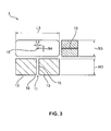
- the Fig. 1 to 4 show a first embodiment of a tile adjuster 1.
- Fig. 1 shows the Fliesenjustiervorraum 1, consisting of a Fliesenjustierstab 2 and a Fliesenfixierelement 3 in the assembled state on a first tile 4 and a second tile 5.
- the two tiles are 4.5 only for illustration of the embodiment and are not part of the invention.
- the tiling adjusting rod 2 comprises a transverse part 7, formed as a plate, and a rod 8 located vertically on the transverse part 7.
- the transverse part 7 is located below the first tile 4 and the second tile 5.
- the rod 8 projects through a tile joint 6 between the first Tile 4 and the second tile 5 through.
- the tile fixing element 3 is placed on the rod 8 and presses the first tile 4 and the second tile 5 flat against the cross member. 7
- Fig. 2 shows the Fliesenjustierstab 2 in a side view and in a plan view.
- the rod 8 extends along a longitudinal axis 14.
- a corrugation 10 is formed over its entire length.
- This corrugation 10 is formed rack-shaped and includes a plurality of teeth. These teeth are perpendicular to the longitudinal axis 14.
- the rod 8 comprises a predetermined breaking point 9.
- This predetermined breaking point 9 is formed as a Querterrorismsseinschnürung.
- the rod 8 extends over a first height H1 and a second height H2.
- the corrugation 10 is attached.
- the second height H2 with 6 mm, the Querterrorismsseinschnürung and thus the predetermined breaking point 9 is formed.
- the cross member 7 is formed as thin as possible with a thickness D of 2 mm and can thereby be sunk in the adhesive bed between the wall or floor and the tiles 4, 5.
- the plate-shaped transverse part 7 extends over a first length L1 of 50 mm and a first width B1 of 35 mm.
- the cross section of the rod 8 measures a second length L2 of 2 mm and a second width B2 of 1 mm.
- the cross member 7 is thus designed substantially larger than a cross section of the rod 8.
- a ratio of the second length L2 to the first length L1 ⁇ 0.2.
- a ratio of the second width B2 to the first width B1 is preferably ⁇ 0.2. This ensures that the plate-shaped cross member 7 is large enough to at least under two tiles 4, 5 extend.
- the cross section of the rod 8 must be small enough to extend through the narrow tile joint 6.
- the second length L2 of the cross section of the rod 8 corresponds exactly to the desired size of the tile joint 6.
- the rod 8 simultaneously acts as a spacer between the first tile 4 and the second tile 5.
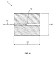
- Fig. 3 shows the tile fixing in a plan view and in two sectional side views. It can be clearly seen that the tile fixing element 3 comprises a receptacle 11, designed as a passage opening 15. A lower end of the tile fixing element 3 is formed as a planar support 13. This planar support 13 ensures uniform force transmission to both tiles 4, 5. In order to ensure easy attachment of the tile fixing element 3 to the rod 8, the passage opening 15 comprises a conical outlet 16.
- the tile fixing element 3 For fixing the tile fixing element 3 on the rod 8, the tile fixing element 3 comprises a holding device 12, designed as a latching tongue.
- This holding device 12 shows Fig. 4 in detail.
- the holding device 12 is inserted into the passage opening 15 and inclined to the longitudinal axis 14. By this inclination of the holding device 12 it is ensured that the corrugation 10 can be pushed past the rod 8 in one direction only on the holding device 12.
- markings can be provided on the tile fixing element 3, so that it is easier for the user to set the tile fixing element 3 on the rod 8 starting with the conical outlet 16.
- a further mark may be provided to align the holding device 12 to the corrugation 10.
- two opposing holding devices 12 are provided in the passage opening 15, so that care must not be taken when attaching the tile fixing element 3 to the rod 8 that the holding device 12 is aligned with the corrugation 10.
- the tile fixing element 3 extends over a third height H3 of 40 mm, a third width B3 of 35 mm, a third length L3 of 80 mm.
- a cross section of the through hole 15 is made rectangular with a fourth width B1 of 1 mm and a fourth length L4 of 2 mm.
- the dimensioning of the passage opening 15 thus corresponds to the cross section of the rod 8.
- the fourth width B4 and the fourth length L4 are preferably slightly larger than the second length L2 and the second width B2. In this case, however, it is ensured that the dimensions of the passage opening 15 and the rod 8 are selected so that always by positive engagement a rotation of the tile fixing element 3 can be transferred to the rod 8.
- Fig. 5 shows a second embodiment of the tile adjuster 1.
- the same or functionally identical components are identified in all embodiments with the same reference numerals.
- the tile adjustment device 1 is designed for the adjustment of tiles 4, 5 at inner edges.
- the cross member 7 may be formed at a fixed angle, in particular 90 °.
- the two legs of the cross member 7 can be flexible to each other, whereby the desired angle is adjustable.
- the tile fixing element 3 has round or curved supports 13 in the second exemplary embodiment. As a result, the predetermined breaking point 9 can be turned off even with an inner edge by the tile fixing element 3.
- Fig. 6 shows a third embodiment of the tile adjuster 1.
- the same or functionally identical components are identified in all embodiments with the same reference numerals.
- the tile adjustment device 1 is also used in the third exemplary embodiment on an inner edge of the tiles 4, 5.
- an intermediate part 17 is attached to the rod 8 here.
- a diameter of a passage 18 in the intermediate part 17 is large enough so that the rod 8 in the passage 18 can rotate freely.
- the predetermined breaking point 9 can be turned off by rotation of the rod 8 unaffected by the intermediate part 17.
- the intermediate part 17 rests with contact surfaces 19 on the flow 4, 5.
- the contact surfaces 19 take the same angle, in particular 90 °, zueinender a like the two legs of the cross member. 7
- Fig. 7 shows a fourth embodiment of the tile adjuster 1.
- the same or functionally identical components are identified in all embodiments with the same reference numerals.
- the Fliesenjustiervortechnisch 1 according to the fourth embodiment is used at the outer edges of two tiles 4, 5 are used.
- the predetermined breaking point 9 and thus the rod 8 are not centered here on the transverse part 7 but at the outermost edge of the transverse part 7.
- the transverse part 7 may consist of two, in particular right-angled, legs and thus a plant for both tiles 4, 5 train.
Landscapes
- Engineering & Computer Science (AREA)
- Architecture (AREA)
- Civil Engineering (AREA)
- Structural Engineering (AREA)
- Finishing Walls (AREA)
Priority Applications (1)
| Application Number | Priority Date | Filing Date | Title |
|---|---|---|---|
| EP09015147A EP2330261A1 (fr) | 2009-12-07 | 2009-12-07 | Dispositif d'ajustement de carrelages |
Applications Claiming Priority (1)
| Application Number | Priority Date | Filing Date | Title |
|---|---|---|---|
| EP09015147A EP2330261A1 (fr) | 2009-12-07 | 2009-12-07 | Dispositif d'ajustement de carrelages |
Publications (1)
| Publication Number | Publication Date |
|---|---|
| EP2330261A1 true EP2330261A1 (fr) | 2011-06-08 |
Family
ID=42229194
Family Applications (1)
| Application Number | Title | Priority Date | Filing Date |
|---|---|---|---|
| EP09015147A Withdrawn EP2330261A1 (fr) | 2009-12-07 | 2009-12-07 | Dispositif d'ajustement de carrelages |
Country Status (1)
| Country | Link |
|---|---|
| EP (1) | EP2330261A1 (fr) |
Cited By (10)
| Publication number | Priority date | Publication date | Assignee | Title |
|---|---|---|---|---|
| ITPD20110295A1 (it) * | 2011-09-20 | 2013-03-21 | Progress Profiles Spa | Distanziatore livellante per la posa di piastrelle, mattonelle e simili con interposizione di fughe |
| CN105822051A (zh) * | 2016-05-10 | 2016-08-03 | 佛山市东鹏陶瓷有限公司 | 瓷砖平整调节块及使用其的陶瓷砖铺贴系统和方法 |
| DE202017101599U1 (de) | 2017-03-20 | 2017-04-03 | Niedermair GmbH | Nivellierungshilfe und Nivellierungsvorrichtung für plattenförmige Boden- oder Wandverkleidungen |
| CN108952117A (zh) * | 2017-05-23 | 2018-12-07 | 张引强 | 装修通用架、铺装结构及房屋装修组装结构 |
| CN109403592A (zh) * | 2018-12-19 | 2019-03-01 | 北方民族大学 | 一种建筑贴瓷砖用平整度辅助装置 |
| CN111433423A (zh) * | 2017-10-10 | 2020-07-17 | 梅创新有限公司 | 瓷砖间隔件 |
| CN111962812A (zh) * | 2020-09-11 | 2020-11-20 | 浙江亚厦装饰股份有限公司 | 一种地面瓷砖安装总成及安装方法 |
| US11002025B2 (en) | 2018-05-09 | 2021-05-11 | Raimondi S.P.A. | Leveling spacer device |
| CN114291539A (zh) * | 2021-12-31 | 2022-04-08 | 广西欧神诺陶瓷有限公司 | 一种单边推砖方法及单边智能推砖系统 |
| EP4008852A1 (fr) * | 2020-12-04 | 2022-06-08 | Raimondi S.p.A. | Dispositif de support pour la pose de carreaux |
Citations (3)
| Publication number | Priority date | Publication date | Assignee | Title |
|---|---|---|---|---|
| US5675942A (en) * | 1995-08-28 | 1997-10-14 | Crawford; Van | Wall panel alignment device and spacer |
| WO2006091606A2 (fr) * | 2005-02-22 | 2006-08-31 | Davinci Italia/Usa Group, Llc | Dispositif d'alignement et de mise a niveau de carreaux et son procede d'utilisation |
| US7257926B1 (en) * | 2006-08-24 | 2007-08-21 | Kirby Mark E | Tile spacer and leveler |
-
2009
- 2009-12-07 EP EP09015147A patent/EP2330261A1/fr not_active Withdrawn
Patent Citations (3)
| Publication number | Priority date | Publication date | Assignee | Title |
|---|---|---|---|---|
| US5675942A (en) * | 1995-08-28 | 1997-10-14 | Crawford; Van | Wall panel alignment device and spacer |
| WO2006091606A2 (fr) * | 2005-02-22 | 2006-08-31 | Davinci Italia/Usa Group, Llc | Dispositif d'alignement et de mise a niveau de carreaux et son procede d'utilisation |
| US7257926B1 (en) * | 2006-08-24 | 2007-08-21 | Kirby Mark E | Tile spacer and leveler |
Cited By (14)
| Publication number | Priority date | Publication date | Assignee | Title |
|---|---|---|---|---|
| ITPD20110295A1 (it) * | 2011-09-20 | 2013-03-21 | Progress Profiles Spa | Distanziatore livellante per la posa di piastrelle, mattonelle e simili con interposizione di fughe |
| EP2573296A1 (fr) * | 2011-09-20 | 2013-03-27 | Progress Profiles SPA | Dispositif d'espacement de carreaux muraux, carreaux de pavement et analogues pour assurer un espacement |
| US8635815B2 (en) | 2011-09-20 | 2014-01-28 | Progress Profiles Spa | Leveling spacer for laying wall tiles, paving tiles and the like with the interposition of gaps |
| CN105822051A (zh) * | 2016-05-10 | 2016-08-03 | 佛山市东鹏陶瓷有限公司 | 瓷砖平整调节块及使用其的陶瓷砖铺贴系统和方法 |
| DE202017101599U1 (de) | 2017-03-20 | 2017-04-03 | Niedermair GmbH | Nivellierungshilfe und Nivellierungsvorrichtung für plattenförmige Boden- oder Wandverkleidungen |
| DE102018102678A1 (de) | 2017-03-20 | 2018-09-20 | Thomas Niedermair und Daniel Singer GbR (vertretungsberechtigter Gesellschafter Thomas Niedermair, 85625 Glonn) | Nivellierungshilfe, Nivellierungsvorrichtung für plattenförmige Boden- oder Wandverkleidungen und Verfahren zum Verlegen von plattenförmigen Boden- oder Wandverkleidungen |
| CN108952117A (zh) * | 2017-05-23 | 2018-12-07 | 张引强 | 装修通用架、铺装结构及房屋装修组装结构 |
| CN111433423A (zh) * | 2017-10-10 | 2020-07-17 | 梅创新有限公司 | 瓷砖间隔件 |
| US11002025B2 (en) | 2018-05-09 | 2021-05-11 | Raimondi S.P.A. | Leveling spacer device |
| CN109403592A (zh) * | 2018-12-19 | 2019-03-01 | 北方民族大学 | 一种建筑贴瓷砖用平整度辅助装置 |
| CN111962812A (zh) * | 2020-09-11 | 2020-11-20 | 浙江亚厦装饰股份有限公司 | 一种地面瓷砖安装总成及安装方法 |
| EP4008852A1 (fr) * | 2020-12-04 | 2022-06-08 | Raimondi S.p.A. | Dispositif de support pour la pose de carreaux |
| CN114291539A (zh) * | 2021-12-31 | 2022-04-08 | 广西欧神诺陶瓷有限公司 | 一种单边推砖方法及单边智能推砖系统 |
| CN114291539B (zh) * | 2021-12-31 | 2023-12-26 | 广西欧神诺陶瓷有限公司 | 一种单边推砖方法及单边智能推砖系统 |
Similar Documents
| Publication | Publication Date | Title |
|---|---|---|
| EP2330261A1 (fr) | Dispositif d'ajustement de carrelages | |
| EP2076950B1 (fr) | Dispositif passe-câble à vis | |
| EP2309552A1 (fr) | Réception de serrage et dispositif de fixation pour la fixation de composants en forme de plaques et procédé de fabrication du dispositif de fixation | |
| EP3649353A1 (fr) | Système de fixation | |
| EP2246577A1 (fr) | Elément de fixation | |
| EP4100586B1 (fr) | Dispositif de fixation, unité d'installation et procédé d'installation d'un boulon à tête rectangulaire sur un rail d'ancrage | |
| DE102020110550B4 (de) | Modulklemme, Verfahren zur Befestigung von Solarmodulen, Verbindungsanordnung zur Befestigung eines Solarmoduls und Anordnung mit Verbindungsanordnung und Solarmodul | |
| DE202007003675U1 (de) | Vorrichtung zur Befestigung von Beschlagteilen an Hohlprofilen | |
| DE9216499U1 (de) | Rohrschelle | |
| DE102013105257B4 (de) | Doppelkeil zum Rahmensetzen | |
| EP2660403B1 (fr) | Support pour matière isolante | |
| DE9306773U1 (de) | Befestigungsvorrichtung aus Kunststoff, insbesondere für Platinen | |
| EP3037682B1 (fr) | Élement de fixation destine a fixer des composants de construction sur des parois de batiment isolees | |
| EP2333220B1 (fr) | Barre de dormant et procédé de rembourrage arrière d'une tel barre de dormant | |
| DE202009016627U1 (de) | Fliesenjustiervorrichtung | |
| AT525006A1 (de) | Montageprofil | |
| EP0859092B1 (fr) | Dispositif de fixation pour appareil à encastrer sous la forme d'un évier encastrable ou similaire sur une plaque de support | |
| DE102012102497B4 (de) | Verbinder, Werkzeug zur Montage und Verwendung eines Verbinders | |
| EP2387968B1 (fr) | Dispositif de fixation d'une prothèse dentaire amovible sur une prothèse dentaire fixe | |
| DE202019103487U1 (de) | Spreizbarer Eckwinkel | |
| DE202011052516U1 (de) | Befestigungseinrichtung für ein Flächenelement in einem unterhaltungselektronischen Gerät | |
| DE202009010497U1 (de) | Winkel zur Befestigung eines Bauelementes | |
| DE29703632U1 (de) | Halte- und Ausgleichselemente für Wandverkleidungsteile | |
| EP1735539A1 (fr) | Systeme de fixation | |
| DE102022105689A1 (de) | Toleranzausgleichsvorrichtung |
Legal Events
| Date | Code | Title | Description |
|---|---|---|---|
| PUAI | Public reference made under article 153(3) epc to a published international application that has entered the european phase |
Free format text: ORIGINAL CODE: 0009012 |
|
| AK | Designated contracting states |
Kind code of ref document: A1 Designated state(s): AT BE BG CH CY CZ DE DK EE ES FI FR GB GR HR HU IE IS IT LI LT LU LV MC MK MT NL NO PL PT RO SE SI SK SM TR |
|
| STAA | Information on the status of an ep patent application or granted ep patent |
Free format text: STATUS: THE APPLICATION IS DEEMED TO BE WITHDRAWN |
|
| 18D | Application deemed to be withdrawn |
Effective date: 20111209 |